![]()
USER MANUAL
![[Alt text was not generated.]](UM-web-resources/image/cover.png)
Lightware advanced room automation
(LARA)
Software Platform
All presented functions refer to the indicated products. The descriptions have been made while testing these functions in accordance with the indicated Hardware/Firmware/Software environment:
|
LARA software |
v1.3.3b2 |
|
v2.0.0b27 |
|
|
Lightware Device Updater V2 (LDU2) |
v2.36.0b8 |
Document Revision History
|
Rev. |
Release date |
Changes |
Editor |
|
v1.0 |
2023-03-22 |
Initial version |
Laszlo Zsedenyi |
|
. . . |
|||
|
v3 |
2025-12-12 |
Added Account deletion request section |
Tamas Forgacs |
|
v4 |
2026-03-05 |
Major updates for the LARA v1.3.3b2 and v2.0.0b27; added individual LARA updating over LDU2 section; added TPN-MMU series support, added Password protection for touchpanels section; updated Sink driver modules |
Tamas Forgacs |
Contact Us
+36 1 255 3800
+36 1 255 3810
Lightware Visual Engineering PLC.
Gizella 51-57, Budapest H-1143, Hungary
©2026 Lightware Visual Engineering. All rights reserved.
All trademarks mentioned are the property of their respective owners.
Specifications are subject to change without notice.
Thank You for choosing LARA. In the first chapter we would like to introduce the software, highlighting the most important features in the sections listed below:
1.1. Introduction
What is LARA?
Lightware Advanced Room Automation (LARA) is a future-proof room automation platform. This software can be used for making controlling functions in meeting rooms.
Where Can You Find It?
It runs integrated in Taurus UCX, DCX, UCX-TPX, UCX-TPN, MMX2 series devices, TPN-CTU-X50 control unit and the TPN-MMU series matrix management units configurable via a browser. Meeting participants can control the devices in the room through a touch panel.
Basics

|
Room integration |
|
The keyword is: room. LARA is developed for meeting room size environment. |
|
![[Alt text was not generated.]](UM-web-resources/image/Feat_Separated_tool.png)
|
Separated SW tool |
|
LARA is part of the Lightware product, however, it is an independent entity in the device. Since the device is protected with a password, LARA is also safe from unwanted modifications. |
|
![[Alt text was not generated.]](UM-web-resources/image/Feat_Taurus.png)
|
Availability |
|
LARA is available in Taurus UCX, Taurus DCX, UCX-TPX and UCX-TPN devices, as well as in MMX2 and TPN-MMU devices. |
Key Benefits
![[Alt text was not generated.]](UM-web-resources/image/Feat_JavaScript.png)
|
Open Integration |
|
Controlling any device that supports open protocols (REST, TCP/IP, LW3, etc). No need for certificated training, as LARA is based on JavaScript. |
|
![[Alt text was not generated.]](UM-web-resources/image/Feat_NoController.png)
|
No External Controller |
|
LARA is in the Lightware products (for now in Taurus and MMX2) and can be used to connect and control third-party devices. No need to purchase an extra controller box. |
|
![[Alt text was not generated.]](UM-web-resources/image/Feat_Configuration_cloning.png)
|
Up/downloading the Configuration |
|
The full LARA configuration can be downloaded as a ZIP file. The file can be uploaded to the same device or to another device of the same type. |
|
![[Alt text was not generated.]](UM-web-resources/image/Feat_Expandable.png)
|
LARA is Expandable |
|
The modular structure, the re-usable Modules and the continuous development mean more and more new features. The software contains many variable built-in factory modules and can be expanded with downloadable contents as well. |
Solution for Meeting Rooms
LARA is a software platform that has been designed mainly for controlling meeting rooms. While developing LARA, the experiences of the popular Event Manager - which can be found in numerous Lightware devices - have been applied. The platform is designed and developed by Lightware Visual Engineering.
With LARA, you can automate your meeting rooms, create or re-use software Modules by using the power of JavaScript, control the behavior of the Taurus and connect it to other third-party devices or services, or do virtually everything that is possible.
Supported Devices
LARA is available in the following devices:
![[Alt text was not generated.]](UM-web-resources/image/Taurus_UCX_RB.png)
|
![[Alt text was not generated.]](UM-web-resources/image/Taurus_DCX_RB.png)
|
|||
|
UCX-2x1-HC30 UCX-2x2-H30 UCX-4x2-HC30 UCX-4x2-HC30D |
UCX-1x1-C40 UCX-2x1-HC40 UCX-2x2-H40 UCX-4x2-HC40 UCX-4x2-HC40D UCX-4x3-HC40 UCX-4x3-HC40-BD UCX-4x3-HCM40 |
UCX-1x1-C60 UCX-2x1-HC60 UCX-2x2-H60 UCX-4x2-HC60 UCX-4x2-HC60D UCX-4x3-HC60 UCX-4x3-HC60-BD |
DCX-2x1-HC10 DCX-3x1-HC20 |
DCX-3x1-HC21 |
|
|
![[Alt text was not generated.]](UM-web-resources/image/Taurus_TPX_RB.png)
|
|||
|
MMX2-4x1-H20 MMX2-4x3-H20 |
UCX-2x1-TPX-TX20 UCX-4x3-TPX-TX20 UCX-3x3-TPX-RX20 |
DCX-3x1-TPX-TX10 |
||
|
|
![[Alt text was not generated.]](UM-web-resources/image/Taurus_TPN_RB.png)
|
|||
|
TPN-MMU-X100 TPN-MMU-X100-20 |
TPN-CTU-X50 |
UCX-2x1-TPN-TX20 UCX-4x3-TPN-TX20 |
DCX-3x1-TPN-TX10 |
|
LARA Version
ATTENTION!The LARA versions may contain big differences. This User Manual is based on a certain version of LARA that is displayed on the bottom of each page. Please check the LARA version of your device. LARA comes with the Taurus/MMX2/TPN-CTU-X50 firmware package but before the device is updated, please read the Old/New Version Handling section.
1.2. Limitations and Capabilities
Please consider the following when using LARA:
▪The Taurus/MMX2/CTU configuration contains the whole LARA configuration as well. If the device configuration is handled with Bulk management or with the Backup/Restore feature, LARA settings can be preserved.
▪If LARA is running when the Lightware device (that runs LARA) is restarted, LARA will run automatically again.
▪A connected or an external device can be accessed via an Instance. (See more information about the Instances in the Modules and Instances section.)
▪When LARA is running, all the defined Instances run together.
▪At most 12 Instances can be run parallel if the complexity of the Instances are at 'average' level (see the specification below of a complex sample configuration).
▪The storage space is 128 MB for the Modules, Instances, user Module content and all codes.
▪The available RAM is 128 MB, LARA uses 80 MB in factory default state.
▪Restoring the factory default settings in the UCX/MMX device will delete the LARA configuration.
The Specifications of a Complex Sample Configuration
▪It consists of 8 Instances:
=5 from the Generic-tcp-ip-client Module,
=1 from the SDVoE Module with maximum 20 TPN/OPTN endpoint devices,
=1 from the User panel Module, and
=1 from the Logic Module.
This configuration needs cca. 115 MB RAM space when running.
ATTENTION!It is recommended to use 8 instances maximum for stable performance. Merge the function blocks if you would need more. Please contact our support services for assistance if the project complexity requires more instances.
1.3. Release Notes
The purpose of this document is to provide updates, bug fixes, and tips for LARA recent release.
1.3.1. LARA v1.3.3b2
The purpose of this document is to provide updates, bug fixes, and tips for LARA recent release.
Major bug-fixes and improvements
▪HC60-BD Taurus devices are now supported
▪Robustness improvement in method execution from a „remote” instance
▪inputSignalPresentStatusChanged event and its corresponding methods added to the Taurus UCX driver
Configuration update
The configurations from earlier LARA releases are expected to work correctly without an update in this LARA revision. If you find runtime or configuration time errors in this LARA revision using an earlier one please contact Lightware support services for assistance.
If the configuration is recognized as having been created in a previous LARA revision, an update hint is shown in Browse Modules after uploading. Module updates are not necessary unless you experience false behavior with the same configuration compared to an earlier LARA version. Otherwise keep the modules intact. In case of an update performed, check the Custom Code and restore your earlier modifications if necessary.
Wizard for typical room applications
Our online Wizard service that generates typical LARA configurations, has been extended with User Management. Basic touchpanel, Cisco and Poly MTR room types are supported.
https://wizard.lightware-lara.com
Hints, limitations, known issues:
▪The SDVoE driver is recommended only up to 20 TPN devices. For more devices, please contact Lightware support services for assistance.
▪For using LARA in UCX HC60 series, disregard the warning about the non-supported revision in case of running configurations built in previous LARA revisions. It has no any effect on performance.
▪Device Real Time Clock shall be set up for the successful LARA authentication
▪It is recommended to erase your browser's cache at the first use of the firmware or LARA. Without erasing the cache the browser may use the previous (cached) version of some GUI pages, without the functions to launch LARA from web-LDC.
▪If the configuration download does not work, please enable pop-up windows.
▪It is recommended to use 8 instances maximum for stable performance. Merge the function blocks if you would need more. Please contact our support services for assistance if the project complexity requires more instances.
▪Session Management - Timeout: In case of inactivity, the user is logged out after 30 minutes, which can be extended by a pop-up message 5 minutes before the expiration date. The extension only renews the inactivity time, it does not extend the 120-minute absolute expiration time
▪Stream Deck device need to be disconnected before stopping or restarting the LARA configuration (driver is available in Early Access Program)
▪If you use more state variables in the Custom Code of the Rule, also use all the affected variables in the Condition fields
1.3.2. LARA v1.3.2b1
The purpose of this document is to provide updates, bug fixes, and tips for LARA recent release.
Major bug-fixes and improvements
▪HC60 series of Taurus devices are now supported (disregard the warning about the non-supported revision from earlier Taurus drivers)
▪Icron Driver now supports the network separation features of the Taurus TPX and CTU devices
▪Bugfix in CEC module of LARA 1.3.1
▪No error messages in „Taurus” driver in DCX models
▪Loop of "Initializing user panel, it can take up to 1 minute..." issue fixed
▪Robustness improvement in Cisco Integration (instance API behavior fixed)
Configuration update
The configurations from earlier LARA releases are expected to work correctly without an update in this LARA revision. If you find runtime or configuration time errors in this LARA revision using an earlier one please contact Lightware support services for assistance.
If the configuration is recognized as having been created in a previous LARA revision, an update hint is shown in Browse Modules after uploading. Module updates are not necessary unless you experience false behavior with the same configuration compared to an earlier LARA version. Otherwise keep the modules intact. In case of an update performed, check the Custom Code and restore your earlier modifications if necessary.
Protocol drivers
Lightware released protocol LARA drivers (SSH, TCP Server, Telnet, Websocket, UDP), please check out our product portal for download:
https://www.lightware.com/en/products/Software/lara-software#Downloads
Wizard for typical room applications
An online Wizard service has been released, that is developed to make the LARA configuration file generation easy, in a few minutes. Basic touchpanel, Cisco and Poly MTR room types are supported.
https://wizard.lightware-lara.com
Hints, limitations, known issues:
▪The SDVoE driver is recommended only up to 20 TPN devices. For more devices, please contact Lightware support services for assistance.
▪For using LARA in UCX HC60 series, disregard the warning about the non-supported revision in case of running configurations built in previous LARA revisions. It has no any effect on performance.
▪Device Real Time Clock shall be set up for the successful LARA authentication
▪It is recommended to erase your browser's cache at the first use of the firmware or LARA. Without erasing the cache the browser may use the previous (cached) version of some GUI pages, without the functions to launch LARA from web-LDC.
▪If the configuration download does not work, please enable pop-up windows.
▪It is recommended to use 8 instances maximum for stable performance. Merge the function blocks if you would need more. Please contact our support services for assistance if the project complexity requires more instances.
▪Session Management - Timeout: In case of inactivity, the user is logged out after 30 minutes, which can be extended by a pop-up message 5 minutes before the expiration date. The extension only renews the inactivity time, it does not extend the 120-minute absolute expiration time
▪Stream Deck device need to be disconnected before stopping or restarting the LARA configuration (driver is available in Early Access Program)
▪If you use more state variables in the Custom Code of the Rule, also use all the affected variables in the Condition fields
1.3.3. LARA v1.3.1b7
The purpose of this document is to provide updates, bug fixes, and tips for LARA recent release.
Configuration update
The configurations from earlier LARA releases are expected to work correctly without an update in this LARA revision. If you find runtime or configuration time errors in this LARA revision using an earlier one please contact Lightware support services for assistance.
If the configuration is recognized as having been created in a previous LARA revision, an update hint is shown in Browse Modules after uploading. Module updates are not necessary unless you experience false behavior with the same configuration compared to an earlier LARA version. Otherwise keep the modules intact. In case of an update performed, check the Custom Code and restore your earlier modifications if necessary.
Protocol drivers
Lightware released protocol LARA drivers (SSH, TCP Server, Telnet, Websocket, UDP), please check out our product portal for download:
https://www.lightware.com/en/products/Software/lara-software#Downloads
Wizard for typical room applications
An online Wizard service has been introduced in our Early Access Program, please join our community to make the LARA configuration file generation easy, in a few minutes.
https://www.lightware.com/en/news/simplify-audio-visual-room-automation-with-lara
Major bug-fixes and improvements
▪Conditions: Delay panel is only shown up in case of a status variable selected
▪No memory usage increase in case of TCP connection failure
▪Edit button removed from the non-editable module parameters
▪Event assigned to store the GET request result in the Generic LW3 driver
▪Cisco Desk Pro support added to "ciscowebex" module
▪"Subscription Method Template" renamed to “Actions when somebody starts listening to this event” and moved to the bottom of the page
▪The checks for parameter and rule names have been made stricter to prevent unpredictable behavior.
▪Taurus HCM40 driver name changed to "taurus-ucx-hcm-driver"
▪Taurus driver clientConnected changes to false when the network cable is disconnected or Taurus power is lost
▪Icron driver "Leave" method works also with one parameter (“Leave all”)
▪Generic rest client module works properly with the UCX
▪Condition Panel for Instance Parameter bug fixed
▪Loss of "Aliases" bug fixed in Icron and SDVoE drivers
▪Bugfix in conditions: Equals operator works with boolean values as well
▪"Invoke Method" form allows any parameter (with warning in case of mismatch)
▪Disabled Rules are no longer registered
▪Name validation rules changed
▪TCP Client module: receive events improved, hex delimiter parsing bug is fixed
▪Rule trigger type de- and re-selection to "Timed based trigger" is working now
▪LW3 driver template event parameters are also shown in the form
▪It is detected if more module variables created with the same name
▪New Event Parameters for frameReceived event in order to process the received binary messages
▪DOM manipulation methods extended with instanceID parameter to avoid "broadcasting”
▪"Constant" has been set as default selections for Action Step parameters
▪removeElementAttribute method has been added
▪Serial command injection has been added to the SDVoE driver
▪Clicking out of the box does not close the pop-up window in form editing
▪Methods Editor layout has been improved (to be similar to Rule and Event editors)
▪CR has been removed from LWROS commands
▪TCP reconnections happen no more frequently than specified
▪Improved module description formatting
▪At driver upload, driver name is set to the filename by default
▪Events that use event templates are now supported in Rules' Condition and Action Step Wizard.
▪Saving events with invalid values is no longer possible.
▪Custom Code editing is now working in Mozilla browser
▪Boolean method parameter has a default value on the method calling GUI
▪No more "base module" in Logic and Service category
▪Number type parameter does not accept string type
▪Usage of dot ('.') in saving a module is allowed
▪Scheduled event can be created with Rule Editor
▪No UCX-CTU-* driver logs error on startup
▪No error logs in configs from 1.1.x and 1.2.0 Taurus driver start up
▪Proper CR characters are used in LG driver instead of LF
▪Interferences between user panel sliders have been eliminated
Hints, limitations, known issues:
▪Device Real Time Clock shall be set up for the successful LARA authentication It is recommended to erase your browser's cache at the first use of the firmware or LARA. Without erasing the cache the browser may use the previous (cached) version of some GUI pages, without the functions to launch LARA from web-LDC. If the configuration download does not work, please enable pop-up windows.
▪It is recommended to use 8 instances maximum for stable performance. Merge the function blocks if you would need more. Please contact our support services for assistance if the project complexity requires more instances.
▪Session Management - Timeout: In case of inactivity, the user is logged out after 30 minutes, which can be extended by a pop-up message 5 minutes before the expiration date. The extension only renews the inactivity time, it does not extend the 120-minute absolute expiration time
▪Stream Deck device need to be disconnected before stopping or restarting the LARA configuration (driver is available in Early Access Program)
▪If you use more state variables in the Custom Code of the Rule, also use all the affected variables in the Condition fields
1.3.4. LARA v1.3.0b5
What’s new in 1.3.0b5 compared to 1.2.0b40
▪Cisco module updated with new codec types and extended operating modes. Integration parameter names and options changed based on integrators' feed-backs for better understanding. For details please find the Application Notes and Module Info page in LARA.
▪Supporting all UCX and DCX models including the TPX, TPN extenders as well as the Dual Screen Taurus (HCM) in separate LARA driver
▪Drivers for Lightware TPN ecosystem: SDVoE and Icron USB2.0 extender modules to build Media-over-IP applications (Video / Audio / USB matrix switching) including Signal Present status in SDVoE (new since 1.2.2 LARA in CTU)
▪Updating configurations created in 1.1.x and 1.2.0 can be set up in a pop-up window.
▪Separation of Base Module and Driver Module version numbering. Base modules in this release have the initial 1.0.0 versions
▪Default Action Step names are generated automatically.
Using configurations created in earlier LARA revisions:
If the configuration is recognized as having been created in a previous LARA revision, an update window is popped up after uploading. Enable the appropriate module update if you intend to use any of the extended module functionalities with configuration improvement. Otherwise leave the checkboxes unchecked, as modules containing custom JS code may fail.
The configuration is expected to work correctly without an update in this LARA revision. If you find runtime or configuration time errors in this LARA revision using an earlier one please contact Lightware support services for assistance.
Major bug-fixes among many unlisted others:
▪Cisco Module: Taurus standalone and TPX integration via remote serial port communication issues - fixed
▪Issues with Cisco codec control using Taurus RS232 serial port - fixed.
▪Multiple emission of periodic events in each cycle - fixed
▪Status Variable bugs fixed
▪LW3 driver methods error handling bugs - fixed Robustness improvement: Reference to missing instance method call does not hang up the execution of the Action Steps
▪Corrupted configuration shall be detected and not executed - fixed
▪Multiple reception of a message in TCP Client module - fixed
▪Bug-fixes in display/projector and CEC driver modules
▪Bug-fixes in REST Client parameter handling
▪Sliders in Multiple User Panels can not be used separately - fixed Method error message are not logged - fixed
Hints, limitations and known issues:
▪It is recommended to use 8 instances maximum for stable performance. Merge the function blocks if you would need more. Please contact our support services for assistance if the project complexity requires more instances.
▪It is undetected if more module variables created with the same name
▪Rule trigger de- and re-selection to "Timed based trigger" is not working (works only if selected ones)
▪Use ISO basic Latin alphabet only in property names (Events, Methods, Parameters, Rules, ...)
▪Device Real Time Clock shall be set up for the successful LARA authentication
▪Apply Dependency and Custom Code Update in Taurus driver to remove the Missing Node error messages (messages lead to no functional issue, just alarms).
▪Stream Deck device need to be disconnected before stopping or restarting the LARA configuration (driver is coming soon in Early Access Program)
▪For TCP receive in case of Hex delimiter, use even number of hex digits without any spaces instead of the standard escape sequences like \x or 0x
▪LG driver dumps error logs in case of switched off display
▪LW3 driver template event parameters are not shown in the form - processing in JS custom code is required
▪If you use more state variables in the Custom Code of the Rule, also use all the affected variables in the Condition fields
▪False "undefined" error message if SONY Bravia driver is used
▪Session Management - Timeout: In case of inactivity, the user is logged out after 30 minutes, which can be extended by a pop-up message 5 minutes before the expiration date. The extension only renews the inactivity time, it does not extend the 120-minute absolute expiration time
▪It is recommended to erase your browser's cache at the first use of the firmware or LARA. Without erasing the cache the browser may use the previous (cached) version of some GUI pages, without the functions to launch LARA from web-LDC.
▪If the configuration download does not work, please enable pop-up windows.
1.4.1. Taurus UCX HC60 and TPN-MMU Series
DIFFERENCE:The following description is related to the Lightware models only what has unique password protection as follows:
▪UCX-1x1-C60
▪UCX-2x1-HC60
▪UCX-2x2-H60
▪UCX-4x2-HC60
▪UCX-4x2-HC60D
▪UCX-4x3-HC60
▪UCX-4x3-HC60-BD
▪DCX-3x1-HC21
▪TPN-MMU-X100
▪TPN-MMU-X100-20
Short Steps
Step 1.Set the user password in the device.
Step 2.Go to the Settings menu -> System tab and press the Open LARA button.
Detailed steps
Step 1 – Setting the User Password in the Device
Open Lightware Device Controller (LDC) software, press the Discover button and select the desired Lightware device.
OR
Open a web browser and type the following in the address line: (make sure to type https):
https://<IP_address>
TIPS AND TRICKS:In case of TPN-MMU series the IP address can be read out the front panel OLED LCD screen.
The login page appears what request the Username and the password.
First Login
![[Alt text was not generated.]](UM-web-resources/image/TPN-MMU-X100_Top.png)
Username: admin
INFO:The username is always 'admin' and it cannot be changed.
Password: the devices have a random generated factory default password applied to the device during the manufacturing process. This unique password is supplied on a sticker along with the device (on its top).
After the first login with the unique password a custom user password must be set. The new password shall fulfill the following criterias:
▪at least 10 characters
▪no more than 100 characters
▪contains only UTF-8 character (letters, numbers and symbols)
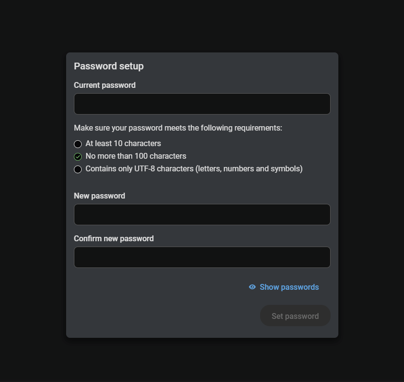
Password setup page
Step 2 – Launching LARA
Go to the Settings menu -> System tab, find the LARA Management / Device Actions section and press the Open LARA button.
![[Alt text was not generated.]](UM-web-resources/image/LARA_launch.png)
1.4.2. Previous Taurus UCX / DCX / MMX2 / TPN-CTU Series
DIFFERENCE:The following description is related to the Lightware models only what has NO unique password protection as follows:
▪UCX-2x1-HC30
▪UCX-2x2-H30
▪UCX-4x2-HC30
▪UCX-4x2-HC30D
▪UCX-1x1-C40
▪UCX-2x1-HC40
▪UCX-2x2-H40
▪UCX-4x2-HC40
▪UCX-4x2-HC40D
▪UCX-4x3-HC40
▪UCX-4x3-HC40-BD
▪UCX-4x3-HCM40
▪DCX-2x1-HC10
▪DCX-3x1-HC20
▪MMX2-4x1-H20
▪MMX2-4x3-H20
▪UCX-2x1-TPX-TX20
▪UCX-4x3-TPX-TX20
▪UCX-3x3-TPX-RX20
▪DCX-3x1-TPX-TX10
▪UCX-2x1-TPN-TX20
▪UCX-4x3-TPN-TX20
▪DCX-3x1-TPN-TX10
▪TPN-CTU-X50
Short Steps
Step 3.Setting the password in the desired UCX/MMX2 device.
Step 4.Enabling port #443.
Step 5.Enabling LARA in the device.
Step 6.Opening LARA in a browser.
Detailed steps
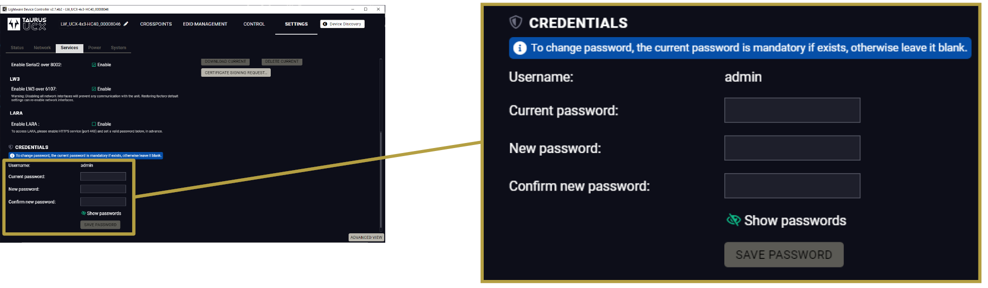
Step 1 – Setting the Credentials in the Desired Taurus Device
▪Start the LDC software and connect to the device or open the web LDC in a browser typing the IP address of the device into the address/URL bar.
▪Navigate to the Settings/Services tab.
▪Set a password for the user 'admin' (if not set previously) and Save it.
Step 2 – Enabling Port #443
▪Navigate to the Settings/Services tab in LDC or in web LDC.
▪See the Network services section and mark the Enable port 443 setting.
![[Alt text was not generated.]](UM-web-resources/image/LDC_Settings_Network_port443.png)
Step 3 – Enabling LARA in the Device
▪Navigate to the Settings/Services tab in LDC or web LDC.
▪See the Network services section and mark the Enable LARA (factory default state is disabled).
![[Alt text was not generated.]](UM-web-resources/image/LDC_Settings_Network_LARA.png)
Step 4 – Internal Time Setting
For the proper working in Taurus and LARA, the internal clock must be synchronized with an NTP server. You can create time-sensitive Rules where the exact time and date is essential. The preparation shall be done in the UCX/MMX2 device:
▪Navigate to the Settings/System tab in LDC or web LDC.
▪Enable NTP by the switch in the Set Date & Time secion.
▪Set the NTP server according to your needs.
![[Alt text was not generated.]](UM-web-resources/image/LDC_Settings_System_DateTime.png)
1.4.3. Opening LARA in a Browser
▪Open a web browser and type the following in the address line: (make sure to type https)
https://<IP_address>/lara
TIPS AND TRICKS:If you select the Settings/System tab, you can open LARA with the OPEN LARA button.
After that you have to enter the user admin and the set password.
ATTENTION!Due to a known issue a malfunction occurs during login. After pressing the login button you will be directed to the web LDC instead of LARA. Navigate to the https://<IP_address>/lara page again to open LARA.
ATTENTION!Session management for security reasons is introduced in UCX and MMX2 devices. When you log into LARA (or in Taurus web LDC) a TCP session is started. After 25 minutes of inactivity you are prompted to confirm to continue the session (in five minutes) or you will be logged out. After two hours you will be logged out automatically regardless of activity.
ATTENTION!Due to a known issue there is a malfunction in Session management: you have to confirm to continue the session every 25 minutes despite the continuous activity.
INFO:When opening LARA for the first time or after factory reset, you must accept the disclaimer statement.
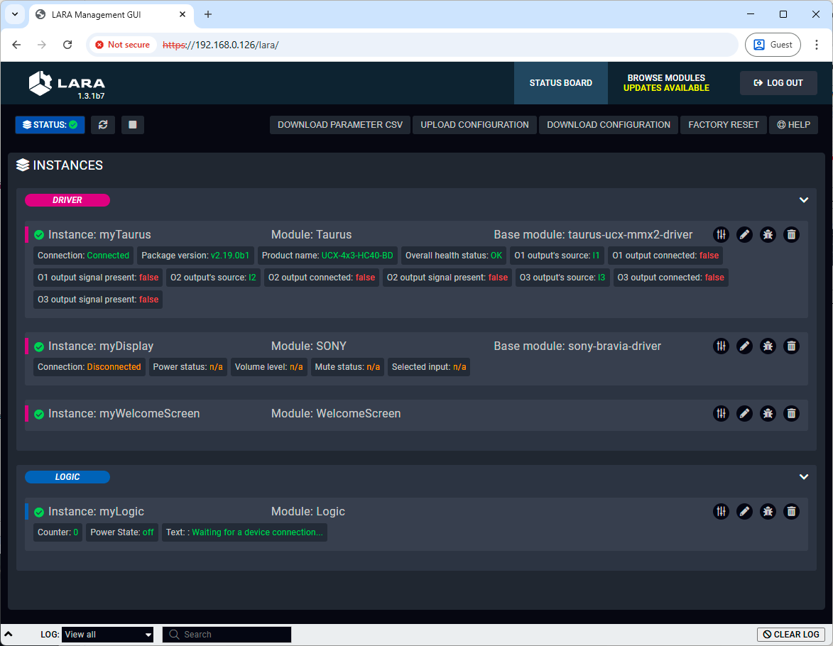
![[Alt text was not generated.]](UM-web-resources/image/Main_screen.png)
The Status Board of LARA – in Factory Default State
1.5. Expanding LARA with Modules
LARA can be expanded with various type of modules (see more details in the The Structure of LARA section on the next page) for the best fitting to the installed AV system.
Two methods is available to add modules to the software:
▪Browsing a built-in factory module;
▪Downloading a module from Lightware's website and adding to the software.
Built-in Factory Modules
Step 1.Select the Browse Modules menu.
Step 2.Select the  icon to add a new factory module.
Step 3.Select the  icon to define an instance for the module.
Downloading a Module from the Website
Step 1.Visit the LARA product page and select the File Downloads section. Many downloadable LARA modules can be browsed there.
Step 2.Download the .zip file to the local computer. The package does not need to be unzipped.
Step 3.Add the new module to the Modules section using a simple drag & drop method.
![[Alt text was not generated.]](UM-web-resources/image/DrogNDrop_New_module.png)
Step 4.Enter the name of the Module.
ATTENTION!Use only ISO basic Latin alphabet characters in the names.
Step 5.Select the  icon to define an instance for the module.
Modules
The Module is the basic building block of LARA. The main purpose of the modular structure is to create re-usable units. The Modules have different functions:
|
|
Driver Module |
Connecting to a device in the room. |
|
|
Logic Module |
Creating the connection between other Modules by defining Rules and the working logic. |
|
|
User Panel Module |
Providing a Graphical User Interface (GUI) for the end-users, e.g. Touch screen control. |
|
|
Script Module |
Any custom software for a specific purpose, e.g. Cisco Webex Module. |
ATTENTION!Please note that the Script Module gives freedom for the user but might break the existing configuration of the LARA. Use this module carefully.
Instances
The Module cannot be used by itself, an Instance has to be created from it. This way of working can be demonstrated with a simple example: if you have an executable file on your computer, that is a Module. When you run it once or multiple times, the windows are the Instances. The software pieces are identical behind the running Instances, however, you can modify their behaviour by giving them different Parameters at start.
Parameter and Value
The modular structure has an effect on the Parameter handling:
The definition of a Parameter: stored in the Module.
The value of the Parameter: stored in the Instance but the default value is stored in the module.
For example: You have two Taurus devices, so you create a Taurus Module. You have to create two Instances and each Instance will contain the IP address of the desired Taurus device.
Driver Module
If you want to make a connection between LARA and an external device, a Driver Module is necessary.
INFO:Everything that is outside LARA is 'external'. The device that runs LARA is also considered external, too. That's why you have to create a Taurus Driver for UCX/MMX2 devices.
The Driver Module can be:
▪Device-specific Driver: e.g. Taurus / MMX2 Driver, Generic Lightware LW3 Driver
▪Communication Driver: e.g. Generic TCP Client Driver, Generic REST API Client Driver
LARA comes with built-in (factory) Modules but you can create your own Module as well, see the Factory Module Descriptions and Touchscreen UI Module chapters.
Logic Module
The Logic Module describes the working logic of the room and/or it can be used for interactions between other Modules. A logic Module creates the connection between the Modules with Rules.
User Panel Module
The User panel Module provides a GUI for the end-users for controlling functions in the room, like a Touch screen controller. HTML content can be uploaded to the Taurus as a pre-formatted HTML file, and it can be edited in the code editor later. The HTML file can be opened in the Touch screen controller. The Module allows modifying the visible elements of the touch screen that makes the GUI interactive. See more information in the Touchscreen UI Module chapter.
![[Alt text was not generated.]](UM-web-resources/image/LARA_module_set2.png)
The Connection of a Driver Module and the Instances
1.7. The Parts of the Automation
RULE = TRIGGER [ +CONDITION ] & ACTION
Rules
The Rule is the part of the Module where the automation steps are described. You can define the following main parts:
▪Trigger: a specific change has happened.
▪Condition (optional): if a Condition is set, it has to be fulfilled to run the Action.
▪Action: execute one or more operations.
![[Alt text was not generated.]](UM-web-resources/image/TCA.png)
The Parts of the Automation – With and Without a Condition
Example
▪Trigger: occupancy sensor sends a signal (GPIO P1 level is high).
▪Condition: a laptop is connected (signal is present on I1).
▪Action: switch on the display, show the laptop image (swith I1 to O1 port and send "powerON" command to the display).
The details of the automation can be found in the The Automation Process section.
This chapter is about the structure and the main parts of LARA.
2.1. The Main Screens
2.1.1. The Status Board Tab
![[Alt text was not generated.]](UM-web-resources/image/Status_board.png)
|
|
LARA status icon |
/ LARA configuration is running / not running |
|
|
Restarting LARA |
|
|
|
Running LARA |
|
|
|
Instances |
List of the currently defined Instances of any Modules with a status icon. |
|
|
Log window |
Displaying system messages, but custom messages can be also displayed. The section is resizable or it can be hidden by the down arrow: |
|
|
Instance buttons |
|
|
|
Info labels |
Only displayed if LARA configuration is running, in order to show valid information. For customizing labels, see the Status Variables section. |


2.1.2. The Browse Modules Tab
![[Alt text was not generated.]](UM-web-resources/image/Browse_modules.png)
|
|
Modules |
List of the used Modules. By pressing the down arrow ,, , the submenu is opened.
|
|
|
Module Handling Buttons |
|
|
|
Module Editing Buttons |
|

When the Firmware is Updated
If the firmware is updated with FW package v2.1 or newer version, the settings of the UCX/MMX2 device can be preserved, as well as the LARA configuration.
Configuration Download and Upload
The full LARA configuration (including Modules, Instances and Parameters with passwords as well) can be downloaded as a ZIP file. The file can be uploaded to the same device or another device of the same type. Use the Upload Configuration/Download Configuration buttons in the upper menu.
![[Alt text was not generated.]](UM-web-resources/image/Config_Down_Up.png)
Factory Reset
All Modules and Instances can be deleted (after confirmation) by pressing the button.
![[Alt text was not generated.]](UM-web-resources/image/Factory_reset.png)
LARA contains factory Modules that cannot be removed. If you upload a configuration/Module, it may contain a newer version of a Module than the existing one of your configuration. In that case, a blue icon ![]() is displayed in the Browse Modules page:
is displayed in the Browse Modules page:
![[Alt text was not generated.]](UM-web-resources/image/Module_update.png)
You can update the Module by pressing the button and the new version will be available in your device.
ATTENTION!Please note that the custom code reverts to the Factory state when updating the module.
INFO:Parameters, Events, Methods and Rules defined by the user in a factory Module are preserved when updating to a new version.
Log Window
The bottom part of the window can be toggled to show the log screen. The messages from each running Instance can be viewed here in real time, so you can follow the state of your system. You can view all Instances at same time or filter the messages to only one Instance. The section is resizable or it can be hidden by the down arrow:
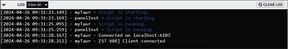
TIPS AND TRICKS:The content of the log window can be copied to the clipboard.
2.2.1. Old/New Version Handling
WARNING!Lightware highly NOT recommends upgrading a working LARA configration to a newer version. Modules and automated process may break after the upgrade procedure.
If you want to update the firmware of your Lightware device that runs LARA, the best way is the follow these steps:
Step 1.Download the LARA configuration (for backup).
Step 2.Update the firmware of the device.
Step 3.Normally, the LARA configuration is kept as is, but if the factory default settings restored from some reason and the configuration disappeared, upload the backup configuration file.
Step 4.The new firmware may contain modules that are newer than in the running configuration. In that case, if you press the blue icon ![]() , the module will also be changed to the new one in the configuration. This step is recommended only if the module does not contain custom mode. After pressing the blue icon, a pop-up window appear which part of the module wanted to be upgraded.
, the module will also be changed to the new one in the configuration. This step is recommended only if the module does not contain custom mode. After pressing the blue icon, a pop-up window appear which part of the module wanted to be upgraded.
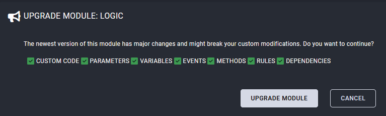
The configuration is expected to work correctly without an update in this LARA revision. If you find runtime or configuration time errors in this LARA revision using an earlier one please contact Lightware support services for assistance.
ATTENTION!Please note that the custom code is deleted when updating the module.
The Main Parts of a Rule – With and Without a Condition
ATTENTION!If your configuration contains more than one Module, it is recommended to create the Rules and the additional components (e.g. unique Methods) in a Logic Module.
2.3.1. The Rule
DEFINITION:The Rule is the part of the Module where the automation steps are described.
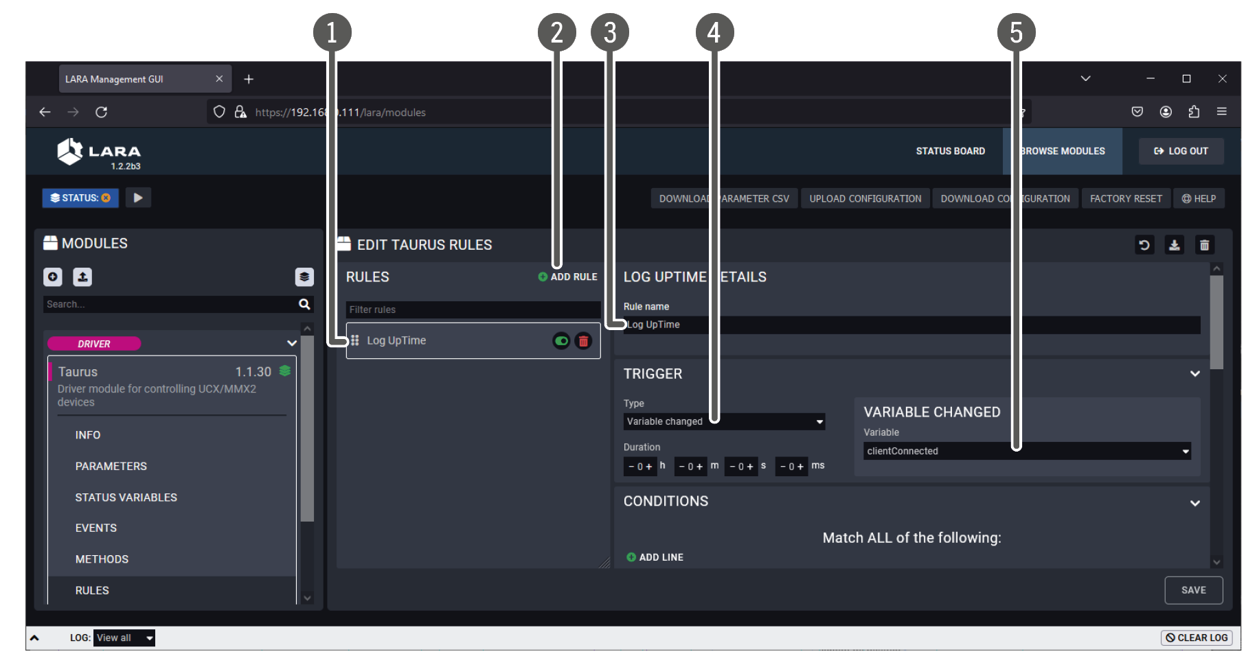
![[Alt text was not generated.]](UM-web-resources/image/Rule_editor.png)
|
|
List of Rules |
The user-defined Rules are listed here. |
|
|
Rule-handling buttons |
|
|
|
Add new Rule |
User-defined Rules can be added with this button. |
|
|
Trigger panel |
Defining the Trigger. |
|
|
Condition panel |
Defining the Condition(s), optional. |
|
|
Action panel |
Defining the Action steps. |

Rule Example
![[Alt text was not generated.]](UM-web-resources/image/Rule_example.png)
The following example shows how the rules are actually working. The situation is simple: the hours of use of the lamp in a projector are wanted to be logged for preparing of the possible lamp change.
What is the trigger?
▪ when the lampHours variable is changed, an action is called.
What is the action?
▪log the message from the lampHours variable.
![[Alt text was not generated.]](UM-web-resources/image/Rule_example_1.png)
Rule for the lamp hours logging
![[Alt text was not generated.]](UM-web-resources/image/Rule_example_2.png)
Action step when the trigger is valid
Applying Regexp Matches in the Conditions
DEFINITION:A regular expression (regexp) is a powerful pattern-matching tool used to find, validate, and manipulate text by defining a sequence of characters that specifies a search pattern.
Applying regexp matching is the best solution when the response of the device (e.g. 3rd-party sink or source devices) contains raw data which keep changing on every requesting, but the response contains a string, word, number sequence, etc everytime. The answer of regexp is always a logical value:
▪true if the expression is found in the data or
▪false if the expression is not found in the data.
Example
![[Alt text was not generated.]](UM-web-resources/image/Rule_example_Regexp.png)
Example for applying regexp matching in a rule
Most of the sink devices send HEX values about their status what is hard to read for the users. For example the power status of a projector is not a simple logical value but a hexadecimal code sequence. The common thing it always contains a pattern what means the projector is powered on.
The trigger type is "Variable changed to value" in our example. Select the variable what you want to watch out of. The operator is the "matches regexp" and the target value can be got from the user manual of the sink device.
Syntax of Regexp
/<pattern>/<flags>
The regexp shall be placed between slash characters ( / ). Variable in the regexp: dot character ( . ).
Several common flags:
▪/i - Performs case-insensitive matching.
▪/g - Performs a global match (find all).
DEFINITION:The Trigger is the occurence (something has changed) that starts the automation process.
Duration Setting
If set, the Trigger must be detectable throughout the Duration time to launch the Action.
Trigger Types
In case of Taurus UCX/MMX2 Module, the following options are available:
Event
The type means: 'something has happened'. This Trigger type is the same EVENT entity that has been used in previous LARA versions.
Variable Changed
A status variable is changed, but the value does not matter, only the fact of the change.
![[Alt text was not generated.]](UM-web-resources/image/Duration_var1.png)
The 'Variable changed' Trigger type and the Actions
Example:
![[Alt text was not generated.]](UM-web-resources/image/EventTriggerSample_VariableChanged.png)
Example for variable changed trigger type
Variable Changed to Value
The new value can be evaluated with the following operators:
|
number |
string / json |
boolean |
|
|
operators |
equal does not equal less than less than or equal greater than greater than or equal |
equals to not equals to contains matches regexp |
equals to not equals to |
![[Alt text was not generated.]](UM-web-resources/image/Duration_var2.png)
The 'Variable changed to value' Trigger type and the Actions
INFO:Above working method is valid in case of the Less than/Greater than operators, too.
Example:
![[Alt text was not generated.]](UM-web-resources/image/EventTriggerSample_VariableChangedToValue.png)
Example for variable changed to value trigger type
Variable Changed Into Range
This type can be used only for number/any types. The options are similar as above, but in this case you can define a range instead of a specific value. The limit values are included in the range.
![[Alt text was not generated.]](UM-web-resources/image/Duration_var3.png)
The 'Variable changed into Range' Trigger type and the Actions
Example:
![[Alt text was not generated.]](UM-web-resources/image/EventTriggerSample_VariableChangedIntoRange.png)
Example for variable changed to value trigger type
ATTENTION!Due to a known issue a malfunction occurs at this Trigger type as the Action should also be run at the red dot marked moments by design. The error will be corrected in a later LARA release.
Time-based Trigger
The Trigger is fulfilled if the current date/time meets the set value.
ATTENTION!For a proper working the Network Time Protocol (NTP) settings must be set precisely. See the Step 4 – Internal Time Setting section.
The Trigger Panel
The Trigger Panel in the Rule Editor
|
|
List of Rules |
The user-defined Rules are listed here. |
|
|
Add new Rule |
Custom Rules can be added with this button. |
|
|
Name of the Rule |
Use only ISO basic Latin alphabet characters in the names. |
|
|
Type of the Trigger |
As follows: ▪Event ▪Variable changed ▪Variable changed to value ▪Variable changed into range ▪Time-based Trigger |
|
|
Variable selector |
In case of Status variable-based Trigger you can select the variable here. |


ATTENTION!When LARA is started, the Status variables are empty in the first moment, if default value is not defined. Then the Status variables are updated immediately, but this 'value change' in the background will launch the 'Variable changed' Trigger types. This may cause Actions to execute. If default value is defined for the variable, this phenomenon can be avoided.
DIFFERENCE:If you have a configuration created with a previous version of LARA, the Events in the Rules are converted to Event-type Triggers.
See more information in the Status Variables section.
'Event' vs. 'Status Variable'
In many cases, you can set the Trigger type as an Event or use a Status variable for the same purpose. Actually, the Event is kept in LARA for compatibility reasons mainly. But there is also another reason to use Status variable instead. If you have a configuration with many Instances and you run the LARA configuration, the Instances are not started at exactly the same time but with a minimal delay – after each other. If a Rule refers to an Instance that has not been started yet, it may happen that the Event would not occur in that moment but later. If your configuration is built with only Status variables as Triggers, this would not happen due to the different working pecularity.
ATTENTION!For a proper working the Network Time Protocol (NTP) settings must be set precisely. See the Step 4 – Internal Time Setting section.
This option is to create a Rule that is triggered by a date/time-related occurance. If the current date/time matches with the set date/time setting (and if the Condition is fulfilled), the Action can be run – select the Once option.
![[Alt text was not generated.]](UM-web-resources/image/Time_based_trigger_screen.png)
The Trigger Panel
2.3.3. The Event
The Event means: something happened. Former LARA versions do not have Trigger but Event. The best way to use is to define a simple occurance as an Event and use the other Trigger types for more complicated cases.
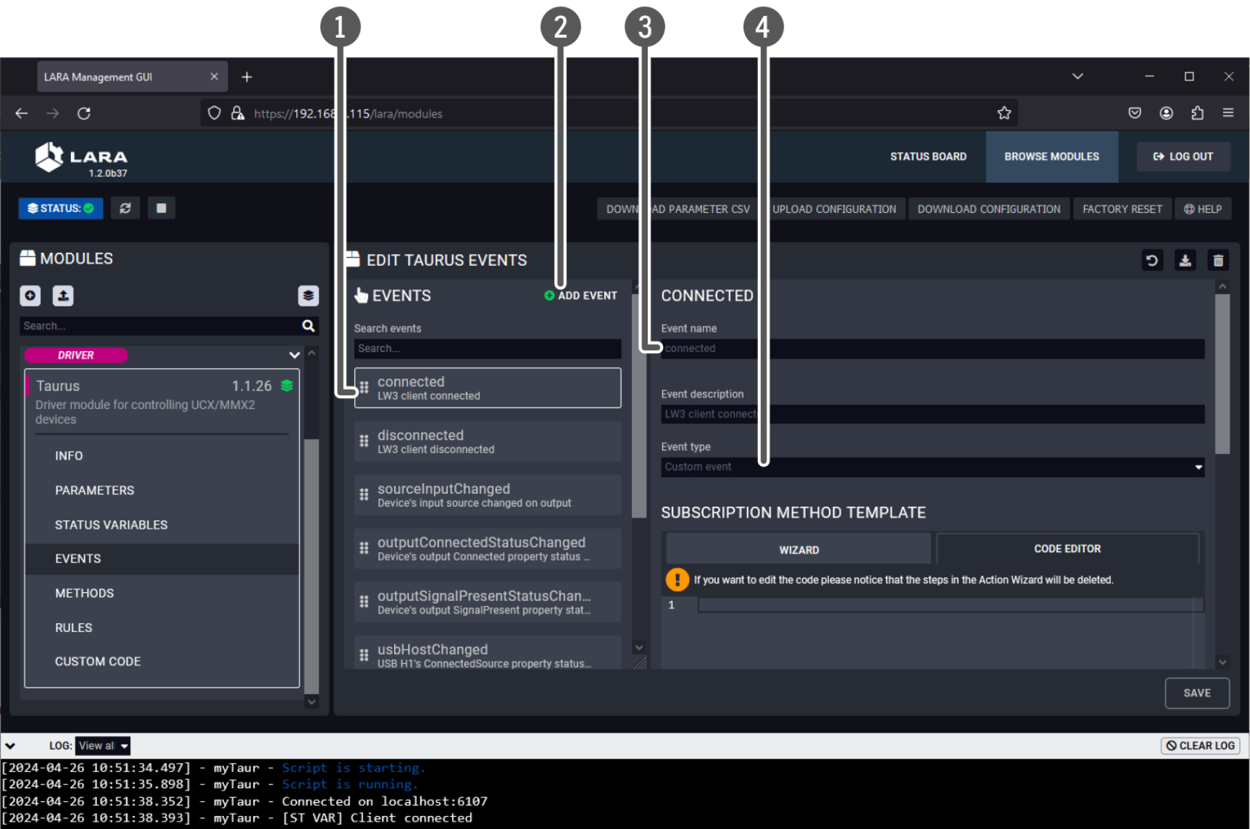
|
|
List of Events |
The factory default and the user-made Events are listed here. Factory Events cannot be edited/deleted. |
|
|
Add new Event |
User-defined Events can be added with this button. |
|
|
Name of the Event |
Use only ISO basic Latin alphabet characters in the names. |
|
|
Type of the Event |
The list of the available types depends on the Module. Factory default options: ▪Custom Event ▪Periodically dispatch Event ▪Dispatch Event at a specific time ▪HTML element clicked – this can be used for User Panel modules, see the Touchscreen UI Module chapter. |
2.3.4. The Condition
DEFINITION:The Condition is one ore more criteria that can be used together with the Trigger to allow running the Action step(s).
Optional, but if it has been set, it has to be fulfilled to run the Action. The way it works: if the Trigger occurs and the Condition can be detected in that moment, the Action can be launched. If the Condition cannot be detected, the Action will not be launched and the Rule process is finished. The process will start again if the Trigger occurs.
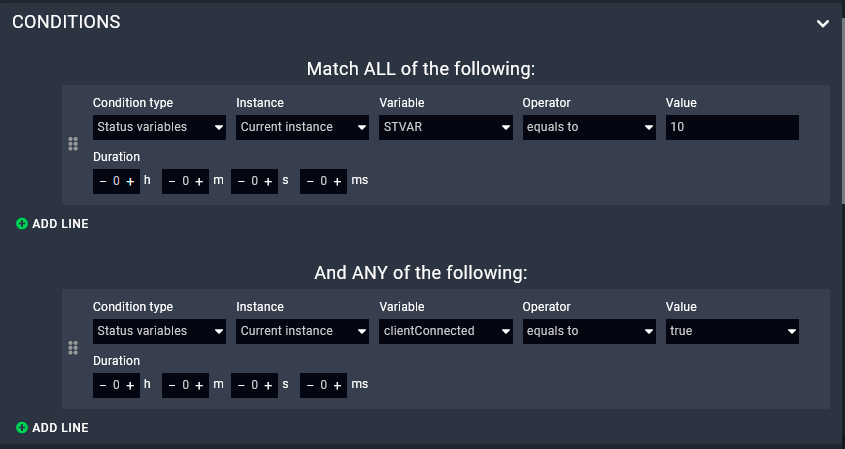
For defining Conditions the following options are available:
▪Defining only one Condition,
▪Defining more Conditions under 'Match ALL of the following' section (this means 'AND' logic): all the defined Conditions must be fulfilled at the same time to run the Action.
▪Defining more Conditions under 'And ANY of the following' section (this means 'OR' logic): if any of the defined Conditions is fulfilled, the Action can be run.
Duration Setting: if set, the Condition must be detectable throughout the Duration time to launch the Action.
ATTENTION!The Duration time is not measured from the Trigger but from the last change of the Status variable. This special feature is valid only if the Condition type is Status variable.
ATTENTION!The logic connection between the two groups is 'AND'.
The Conditions Panel
2.3.5. The Method
DEFINITION:The Method is a pre-defined operation that can be executed as an Action of a Rule.
Methods are just like functions that can be called as an Action of a Rule. The Method can be a factory default Method or a user-defined custom Method. Some typical examples from the Taurus UCX/MMX2 Module:
▪GET: querying a Parameter
▪SET: setting a property
▪OPEN: subscribing to a node path
▪CALLMETHOD: calling an LW3 Method
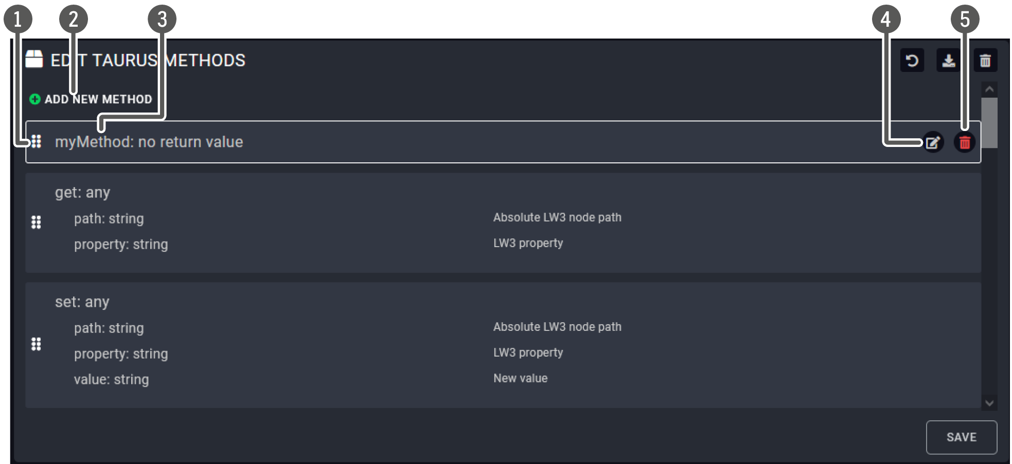
The Method Editor Panel
|
|
List of Methods |
The factory default and the user-made Methods are listed here. |
|
|
Add new Method |
User-defined Methods can be added with this button. |
|
|
Name of the Method |
Use only ISO basic Latin alphabet characters in the names. |
|
|
Editing the Method |
Factory Methods cannot be edited. The icon is displayed if the mouse cursor is above the Method. |
|
|
Deleting the Method |
Factory Methods cannot be deleted. The icon is displayed if the mouse cursor is above the Method. |

User-defined Methods
A Method can be added as follows:
Step 1.Press the Add new Method button in the Methods submenu.
Step 2.Press the button to edit the Method.
Step 3.Name the Method.
Step 4.Add new Method Parameter by the button (optional).
Step 5.Press the Add Method step button in the Code section and define the desired task with the Wizard. The available Action types are the same as described in connection with the Action steps – see the following section. Or select the Code editor and type a custom JavaScript code.
Step 6.Press the Save button.
INFO:The Method Parameter and the Return value can be defined via LARA GUI, the value can be assigned with the Events and Methods debug window. Even tough, the value assingment is not available with Wizard yet but with the Code Editor.
Testing a Method
You can easily try if the defined Method works as it should. Closing the log window is recommended as it may cover the pop up window.
Step 1.Navigate to the Status board.
Step 2.Select the desired Instance and press the button (see below). A new window will pop up showing the defined Events and Methods.
Step 3.Scroll to the desired Method. The desired Method Parameter values can be entered in the textboxes.
Step 4.Press the Invoke <Method_name> Method button.
![[Alt text was not generated.]](UM-web-resources/image/Method_testing.png)
![[Alt text was not generated.]](UM-web-resources/image/Method_testing1.png)
Testing a Method
2.3.6. The Action
DEFINITION:The Action (step) is pre-defined task (operation) that is executed as the part of a Rule.
The Action is part of a Rule. Lightware-made Modules contain default Action types as follows:
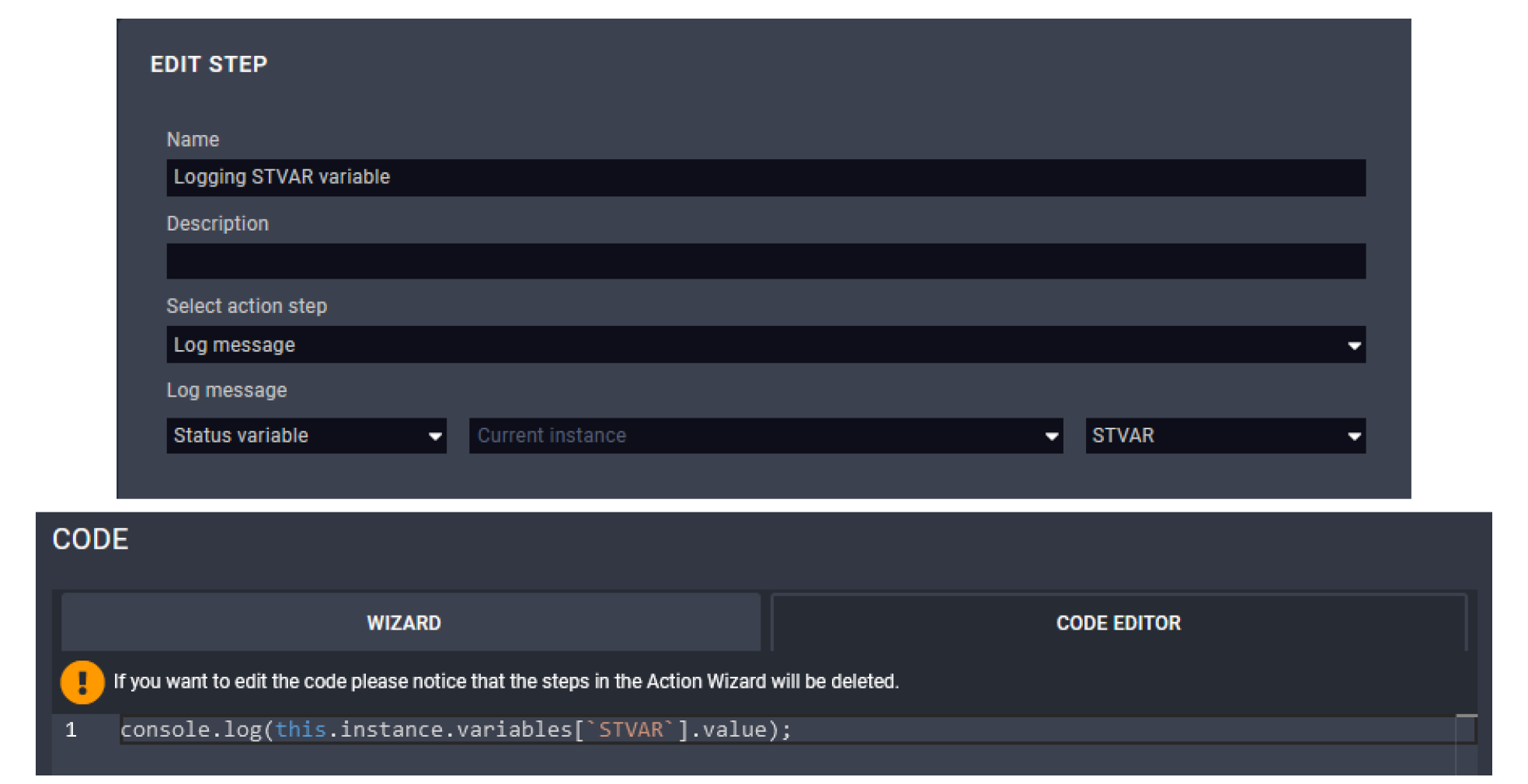
▪Invoke Method: a pre-defined Method (factory or user) can be run.
▪Log message: a message to display in the log window (this can be a constant or a dynamic value).
▪Dispatch Event: a pre-defined Event can be emulated (as if it has happened).
▪Wait: setting a delay (in ms) before/after an Action step.
▪Display information on Status board: a constant or a dynamic value (e.g. a Status variable) can be displayed in the log window; see the Displaying a Status Variable on the Status Board section.
▪Set Status Variable: the value of a variable can be set.
User-defined Action Steps
The Action steps can be added as follows:
Step 1.Create the desired step as a Method (see the previous section).
Step 2.Navigate to the desired Rule and set the Action: select the Invoke Method option.
Step 3.Select the previously set Method from the list.
Wizard vs. Custom Code
The Action step can be added with the Wizard or with the Code Editor as a JavaScript code (based on nodeJS programming language).
ATTENTION!If you change anything in the code, the wizard cannot be used to edit the Action step after that. Furthermore, if you use the wizard after the code editor, the new content would overwrite the code.
Factory default modules contain Info labels that are displayed on the Status Board but custom labels can also be added.
The following notes are referring to the labels:
▪The order of the labels depends on the starting sequence of the Methods.
▪Factory defined labels are being kept up-to-date continuously.
▪The custom labels can be the following:
=The value of a Status variable (e.g. GPIO P1 output value), see the Displaying a Status Variable on the Status Board section,
=A constant value (e.g. 'Hello World!'), see the Displaying a Constant Message on the Status Board section,
=An Instance parameter (e.g. the IP address), see the Displaying an Instance Parameter on the Status Board section,
=A method parameter (only if it is defined as a method step).
![[Alt text was not generated.]](UM-web-resources/image/Info_labels_4.png)
Custom Info Labels (marked) and the Default Labels
2.4.1. Displaying a Status Variable on the Status Board
Factory default modules contain Info labels that are displayed on the Status Board but custom labels can also be added. The label can get the value from a Status variable either as follows:
You can display a Status variable as an Info label on the Status board as follows:
Step 1.Create a Rule and define a Trigger, or select an existing Rule.
Step 2.Press the Add rule action step button in the Action section (Wizard tab).
Step 3.Name the step and select the Display information on Status Board option. Use only ISO basic Latin alphabet characters in the names.
Step 4.Type a label.
Step 5.Select the Status variable value type.
Step 6.Select the desired Status variable.
Step 7.Optionally set the style of the label.
Step 8.Press the Save button (this will close the pop up window) and press Save button in the main window, too.
INFO:The Displaying information on the Status board step can also be defined as a Method.
Example
The following example is about a case when a Status variable is selected from the default list and displayed on the Status Board as an Info label (GPIOP1).
![[Alt text was not generated.]](UM-web-resources/image/Info_labels.png)
Target
If the GPIO P1 output level is changed, the level is displayed and updated on the status board.
Operation
The label is displayed on the Status Board when LARA configuration is started. Once the output level of GPIO P1 is changed, the value is updated.
INFO:The 'GPIOP1' label appears when LARA is started. The Status variable is empty in the first moment (as this Status variable does not have default value). After that the Status variable is updated immediately. This 'value change' in the background would launch the 'Variable changed' Trigger type.
Preparation
▪Taurus UCX/MMX2 Driver is defined under the Modules menu.
▪Instance is created from the Module.
▪The direction of the P1 port is set to Output.
Adding a New Rule
▪Rule name: e.g. Displaying GPIO P1 level
▪Trigger Type: Variable changed
▪Variable Changed: gpioP1Output
▪Action / Add Rule Action step
=Action name: e.g. GPIO1 update
=Select Action step: Display information on Status Board
=Label: e.g. GPIO1
=Value: Status variable, gpioP1Output
=Style: as you wish
TIPS AND TRICKS:This Rule can easily be tested by toggling the GPIO Pin1 output level in LDC or web LDC.
2.4.2. Displaying a Constant Message on the Status Board
You can display a constant message as an Info label on the Status board as follows:
Step 1.Create a Rule and define a Trigger, or select an existing Rule.
Step 2.Press the Add rule action step button in the Action section (Wizard tab).
Step 3.Name the step and select the Display information on Status Board option.
Step 4.Type a label.
Step 5.Select the Constant value type.
Step 6.Type the message that you want to be displayed as a Constant value.
Step 7.Optionally set the style of the label.
Step 8.Press the Save button (this will close the pop up window) and press the Save button in the main window, too.
Constant custom message on the Info label
2.4.3. Displaying an Instance Parameter on the Status Board
You can display a parameter as an Info label on the Status board as follows:
Step 1.Create a Rule and define a Trigger, or select an existing Rule.
Step 2.Press the Add rule action step button in the Action section (Wizard tab).
Step 3.Name the step and select the Display information on Status Board option. Use only ISO basic Latin alphabet characters in the names.
Step 4.Type a label.
Step 5.Select the Instance parameter value type.
Step 6.Select the desired Instance parameter (e.g. ipAddress).
Step 7.Optionally set the style of the label.
Step 8.Press the Save button (this will close the pop up window) and press the Save button in the main window, too.
IP address of the device is displayed on the Info label
DEFINITION:The Status Variable can be used to store a piece of information. e.g. the value of an LW3 property.
Application Modes
▪Value assignment: storing the value of a property,
▪Displaying Information on the Status Board (Info Label),
▪Using as a reference in Rules, see the The Trigger section.
INFO:LARA stores the timestamp of the last change of the variable. Time-sensitive Rules are based on that information (duration setting), see the Time-based Trigger section.
![[Alt text was not generated.]](UM-web-resources/image/myvariable.png)
Value Assignment
Default Status Variables
The factory default Status variables are connected to LW3 properties and they are kept up-to-date in the background continuously.
For creating a unique Status variable and assigning the value, see the following section.
User-defined Status Variables
INFO:Creating the Status variable in the Logic Module is recommended.
You can create a new Status variable as follows:
Step 1.Navigate to the Status variables menu.
Step 2.Press the Add new button in the middle section.
Step 3.Fill the Name and Type fields; Description and Default value are optional. Use only ISO basic Latin alphabet characters in the names.
Step 4.Press the Save button.
Variable types
▪number: for storing numbers (decimals are accepted, divided by a dot).
▪string: for storing characters and text.
▪boolean: true/false.
▪json: any kind of JSON object can be stored.
▪any: any of the types above but without requirements.
ATTENTION!If you use comma as a decimal separator for a number, the value will be handled as a string.
Changing the Value of a User-defined Status Variable
The value of the Status variable can be changed with a Rule Action step or with a pre-defined Method. The value can be:
▪Constant: a static value determined in this window,
▪Instance Parameter: the value is coming from the selected Instance. (The Parameter is defined in the parent Module and the value can be different for each Instance. See the The Inside of the Module section.)
▪Status variable: the value of another Status variable.
▪Method parameter (only if the value is changed with a Method): the parameter defined in the module.
![[Alt text was not generated.]](UM-web-resources/image/chg_myvariable.png)
INFO:The status variables can be displayed on the status board (info label). See the step-by-step description about it in the Displaying a Status Variable on the Status Board section.
2.6. Best Practices
How to Build Your Configuration
When building a LARA configuration with more, than one modules, it is worth to pay attention to:
▪Set the device-specific Methods, Rules and Status Variables in the Driver and Script Modules.
▪Set the Room automation related Rules and Status variables in the Logic Module.
▪When using a User Panel Module, set the HTML-related Events and Rules in the User Panel Module.
These principles help to create re-usable Modules.
Adding a New Module
As mentioned previously, the Driver Module is the interface to a device. A Module can be added on the Browse Modules page with:
▪Pressing the ![]() button and selecting from the available list, or
button and selecting from the available list, or
▪Pressing the ![]() button and adding a previously saved Module (as a ZIP file).
button and adding a previously saved Module (as a ZIP file).

ATTENTION!The default Methods, Parameters and codes of the factory Modules cannot be edited/deleted.
TIPS AND TRICKS:The modul (as a ZIP file) can be added via mouse drag&drop into this window.
Creating Instances
ATTENTION!It is recommended to use 8 instances maximum for stable performance. Merge the function blocks if you would need more. Please contact our support services for assistance if the project complexity requires more instances
Step 1.Navigate to the Browse Modules page.
Step 2.Press the ![]() icon in the top of the Modules section.
icon in the top of the Modules section.
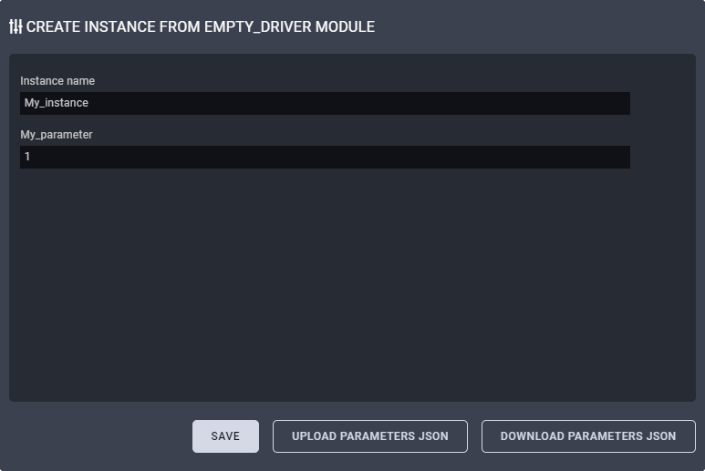
Step 3.Type a name for the Instance and optionally set the value of the defined Parameters (if any). Use only ISO basic Latin alphabet characters in the names.
Step 4.Press the Save button.
INFO:Please note that the name of the Instance cannot be changed in LARA after first saving.
The value of the Parameters can be set later as well:
Step 1.Navigate to the Status Board.
Step 2.Press the ![]() button in the end of the desired Instance line to open the Parameter editor window.
button in the end of the desired Instance line to open the Parameter editor window.
TIPS AND TRICKS:The Parameters and values of the Instance (seen on the screen) can be saved as a JSON file by the download button. Previously downloaded Parameters and values can be uploaded at this step by the upload button.
2.7. Configuration Uploading to Multiple Devices
LARA configuration files and the instance parameters can be uploaded to multiple Taurus devices at the same time using the Bulk Management tool. The software makes possible to copy an automated room's configuration to other ones in one step.
The tool is built in the Lightware Device Controller (LDC) software, the following section desribes the steps of the usage.
2.7.1. Downloading the Configuration Files from LARA
At first, download the required data from LARA what it wanted to be duplicated.
▪Instance parameters (.csv)
▪Configuration files (.zip)
Downloading the Instance Parameters
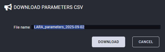
Select the Download Parameter CSV button on the Status board of LARA. Save the CSV file on your local computer.
Downloading the Configuration File
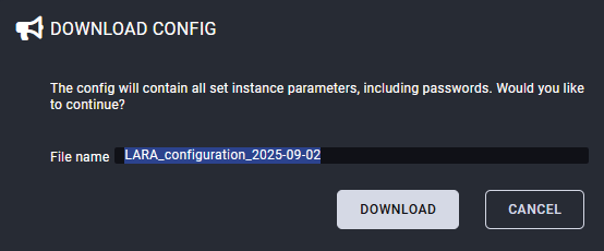
Select the Download Configuration button on the Status board of LARA. Save the ZIP file on your local computer.
2.7.2. Usage of the Bulk Management Tool
The Bulk Management is built in the Lightware Device Controller (LDC) software (it can be downloaded on our website).
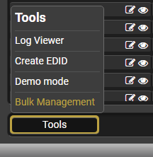
Select the Tools menu on the lower left side of the Device discovery screen. Click on the Bulk Management submenu to open the tool.
Three tabs are available:
▪Network settings - the network preferences can be set and applied on multiple devices.
▪Device configuration - clone files (what can include LARA configuration as well) can be uploaded and applied to multiple Taurus devices. See more details in the Device Configuration Tab section.
▪LARA - instance parameters and LARA configuration files can be uploaded and applied to multiple Taurus devices. See more details in the LARA Tab section.
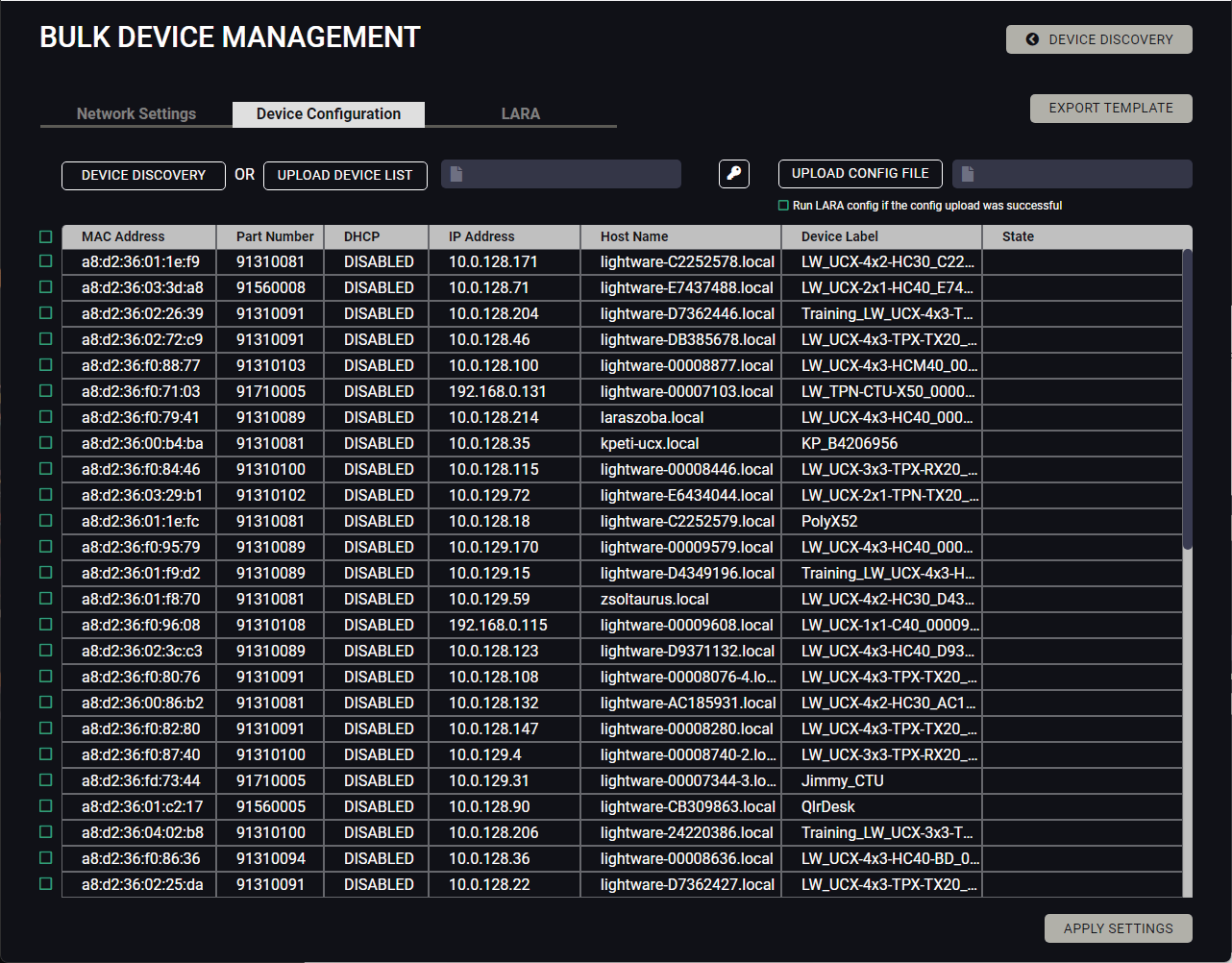
Device configuration clone files can be uploaded to multiple devices at the same time on this tab.
The affected devices can be selected by two methods:
▪using the Device discovery button what discovers the nearby Ligthware devices on the network. Selection can be made by ticking the wished switchers and extenders;
▪using a specific device list uploading a CSV file which contains the IP addresses of the required devices. In this case select the Upload device list button.
Select the Upload config file button and browse the required device configuration clone file. After the devices and the config file are selected, click on the Apply settings button to start the uploading.
ATTENTION!The device configuration clone file can be applied on the same models only. Lightware highly recommends the devices shall be installed with the latest and the same firmware packages.
INFO:Check the Run LARA config if the config upload was successful checkbox in case of there is no unique instance parameters in the LARA configuration only.
LARA configuration and instance parameter files can be uploaded to multiple devices at the same time on this tab.
The affected devices can be selected by the Upload Parameter CSV button. A specific device list can be uploaded in a CSV file which contains the IP addresses of the devices.
Select the Upload LARA Config button and browse the required LARA configuration file.
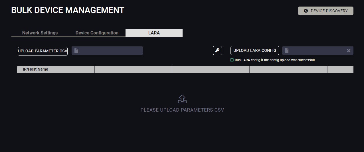
INFO:Check the Run LARA config if the config upload was successful checkbox in case of there is no unique instance parameters in the LARA configuration only.
2.8. Resource Usage Tool
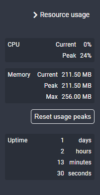
DIFFERENCE:The Resource usage tool is available from LARA v2.0.0 only.
The Resource usage tool can be found in the top right section of the Status board.
It provides helpful information about the actual CPU and memory usage of the LARA modules, continously monitoring and follow the trends. If the memory usage increases continously, it is recommended to optimize some of the modules or user scripts.
2.9. JavaScript Code Examples
The Modules may contain custom codes based on nodeJS programming language. Please find below the following JavaScript example codes that could help you write your custom codes.
Writing something to the log window (comments can be written after double slash)
console.log('Hello world!'); //this is a comment
Writing an error message to the output console (seen at the bottom part of the window, written in red)
console.error('Oh, no! Something terrible has happened!');
Accessing Instance Parameters
console.log('Device IP address is ', params.ip_address);
Waiting for 2000 milliseconds
await new Promise(r => setTimeout(r, '2000'));
Showing/updating information on status board with a given color
this.instance.updateStatus('Today weather', 'Sunny', {color: 'yellow'});
Emitting an Event from an Instance
this.instance.dispatchEvent('resulutionChanged', '1920x1080p60');
Running a custom code 10 seconds later
console.log('Enable the relay');
setTimeout(()=>{
console.log('Disable the relay');
},10000);
Running a code every 5 seconds
setInterval(()=>{
console.log('This is printed every 5 seconds');
},5000);
Running an Action when our Instance has fired an Event
this.instance.on('messageReceived', (message) => {
console.log('A message has just been received:', message)
});
this.instance.dispatchEvent('messageReceived', 'Meow');
Running an Action when another Instance has fired an Event
this.getInstanceById('display').on('volumeChanged', (message) => {
console.log('The display volume has just been changed:', message)
});
Invoking a Method from our own Instance
this.myFancyMethod(param1, param2);
Invoking a Method from another Instance
await InstanceApi.getInstanceById('display').send('powerOn');
Importing nodejs built-in Modules (see this documentation about the available Modules)
//import net Module
var net = require('net');
Writing a file
var fs = require('fs');
fs.writeFileSync(this.instance.getLocalStoragePath()+'/data.txt', 'Hello world');
Reading a file
var fs = require('fs'); // if it was not yet required
var data = fs.readFileSync(this.instance.getLocalStoragePath()+'/data.txt');
More information and examples about file operations on this website.
Sending and receiving response to/from a client over TCP/IP
var net = require('net');
var client = new net.Socket();
client.connect(1337, '192.168.1.1', function() {
console.log('Connected');
client.write('Message from the Client.');
});
client.on('data', function(data) {
console.log('Received: ' + data);
client.destroy(); // terminate client after server's response
});
client.on('close', function() { console.log('Connection closed');
});
Sending an HTTP GET message
const http = require('http');
http.get('http://192.168.0.1', (res) => {
const { statusCode } = res;
const contentType = res.headers['content-type'];
if (statusCode !== 200) {
console.log('Request Failed. Status Code: ', statusCode);
res.resume();
return;
}
res.setEncoding('utf8');
let rawData = '';
res.on('data', (chunk) => { rawData += chunk; });
res.on('end', () => {
console.log('Received: ', rawData);
});
}).on('error', (e) => {
console.error('Got error:',e);
});
Troubleshooting
If "this" cannot be called, the following command can be used instead of "this":
instanceApi.getSelf()
2.10. External Links
The following documentations help becoming a more professional user of LARA:
The webpage of LARA:
The nodeJS programming language – for creating custom codes:
https://nodejs.org/docs/latest/api/
The markdown formatting – for editing a cool Module description:
https://daringfireball.net/projects/markdown/
Reserved Words – good to know when defining Parameters:
https://www.w3schools.com/js/js_reserved.asp
The LARA Wizard is an online, cloud-based tool that helps create customized configurations for LARA. The following sections can be found in the chapter:
3.1. Introduction
LARA Wizard is an easy-to-handle and continuously improving cloud-based tool to create your own LARA configurations without deeper programming knowledge. It helps integrators and AV professionals build powerful room automation setups by answering a few guided questions.
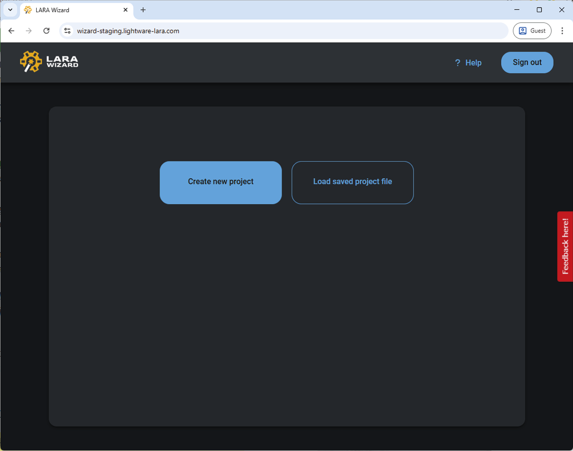
The Direct Link to the LARA Wizard
The LARA Wizard requires a registration that creates a private account and grants access to the LARA cloud storage.
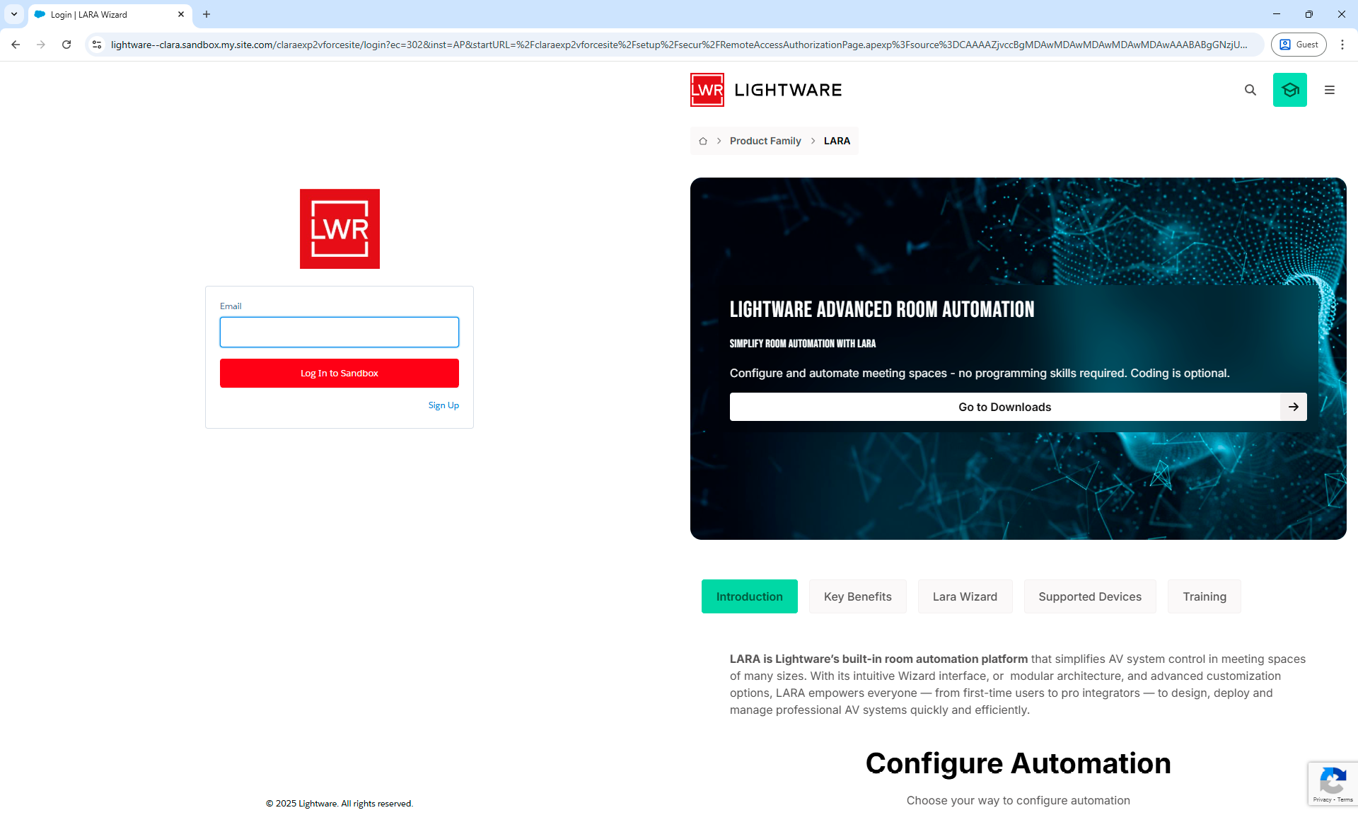
LARA Wizard landing page
3.2. Registration
Using the LARA Wizard requires a log in procedure on the landing page. First visitors shall start the registration process by selecting the Sign Up button.
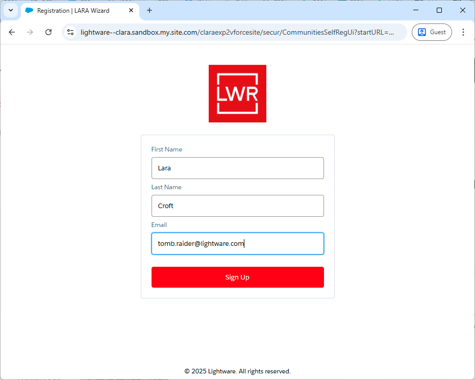
3.2.1. Steps of the Registration
Step 1.Select the the Sign Up option on the landing page.
Step 2.Fill in the registration form with your first name, last name and e-mail address, then click on the Sign Up button.
Registration form for LARA Wizard
Step 3.Check your e-mail. The 6-digit verification code will be sent in e-mail. The code can be used once but the browser that you use can save the login credentials until the signing out.
Step 4.Type the verification code on the LARA Wizard registration page.
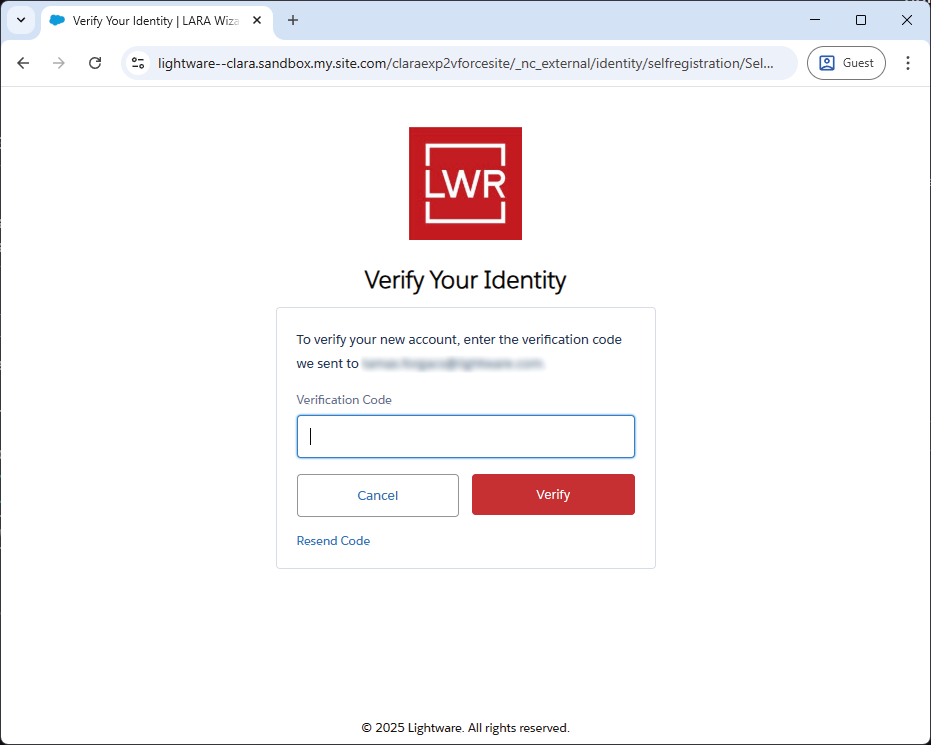
Verify Your Identity page
Step 5.You are in!
LARA Wizard welcome screen
TIPS AND TRICKS:If always the same web browser is used for the LARA Wizard, the verification code will be valid for one week, no need to verify your identity in this period unless choosing the Sign out button.
3.2.2. Account Deletion Request
If the registered account wanted to be deleted by the user, please do the following: write an email about the account deletion request to this e-mail address: marketing@lightware.com.
Required information: the registered LARA Wizard e-mail address.
3.3. The Wizard
There are two options on the LARA Wizard welcome page:
▪Create new project - step by step wizard, which assists you to create your own LARA configuration from scratch.
▪Load saved project file - loading and editing of an existing wizard file.
3.3.1. Creating New Project
Selecting the Create new project button starts with a form where useful information can be added to the project. The minimum requirement is the Project name and the acceptance of the Customer Privacy Policy.
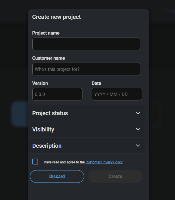
Create new project form
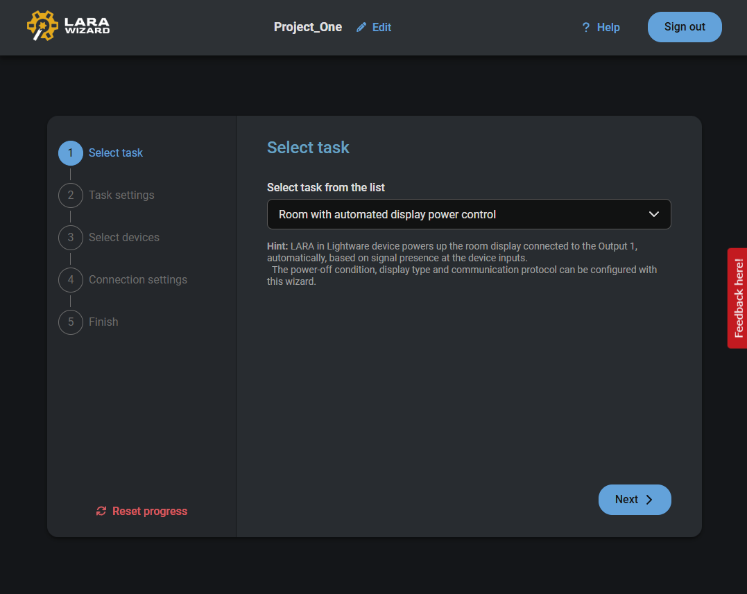
Creating Configuration Step-by-Step
The wizard guides through the steps and helps creating the LARA module file that your project needs. At the end of the procedure the project file and the configuration file can be downloaded to your local computer. The project file (.wizard) can be edited later (see more details about it in the Loading Saved Project File section). The configuration file (.zip) can be uploaded to the local Taurus UCX device (see more details about it in the Uploading the LARA Configuration to a Device section).
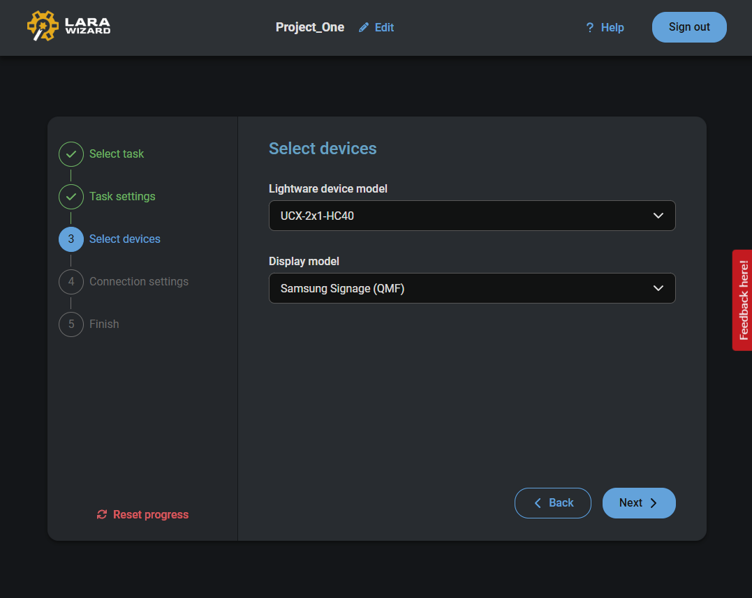
The wizard can be restarted anytime by selecting the Reset progress button.
The LARA Wizard
Online Help is also available for the wizard, which adds additional information for the configuration steps.
3.3.2. Loading Saved Project File
When a project file is saved to the local computer, it can be recalled anytime and edited as you wish.
Step 1.Select the Load saved project file button.
Step 2.Browse the project file (.wizard) on your local computer.
Step 3.After opening the file the project can be edited.
Recalled project file in the LARA Wizard
The modified project file can be saved with a unique name or exported as a configuration file for uploading to a device.
3.4. Uploading the LARA Configuration to a Device
Once the last step (Finish) of the wizard is reached, choose the Download configuration file button. The configuration file (.zip) is downloaded to the local computer.
Steps of the Uploading
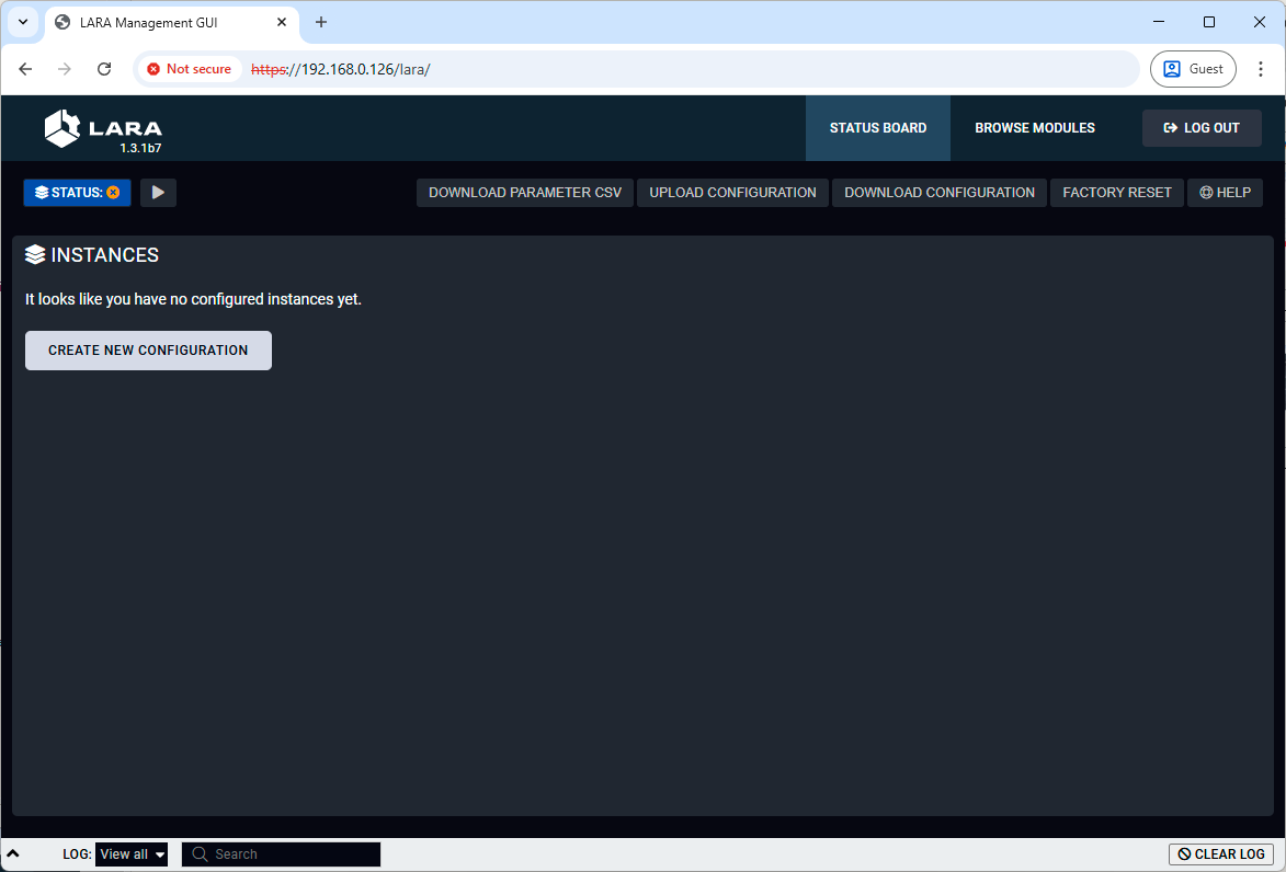
Step 1.Open the LARA of the Taurus UCX switcher or extender - see the details in the How to Access? section.
INFO:Lightware recommends to apply factory default configuration on LARA for a clean start. It can be done selecting the Factory Reset button.
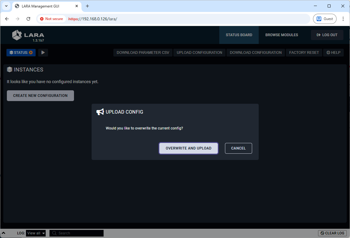
Step 2.Select the Upload Configuration button in LARA to add your configuration file (.zip).
Step 3.Select the Overwrite and Upload button.
Step 4.Wait until the module is uploaded to the device and applied in LARA.
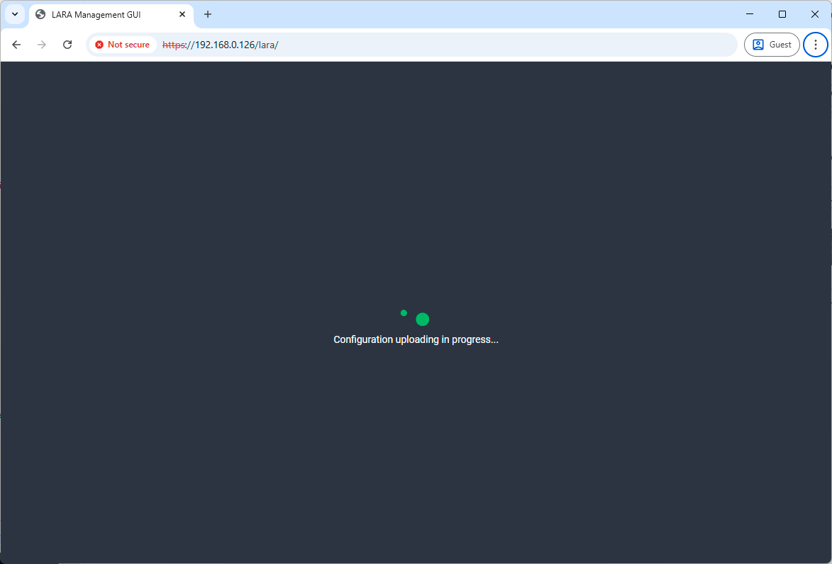
Step 5.It is done! The configuration is uploaded and running on LARA.
4. Factory Module Descriptions
This chapter is about the Modules that have been developed by Lightware. The properties and the configuration steps are described in the coming sections.
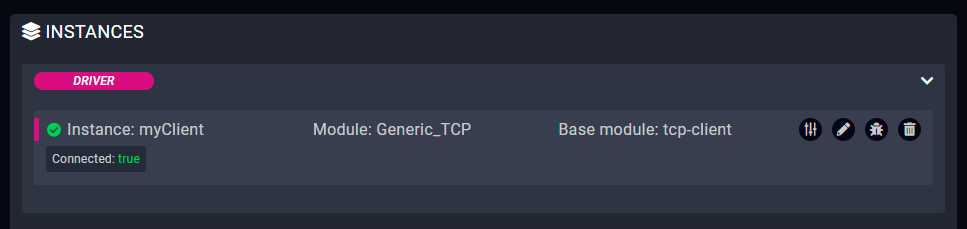
4.1. Generic TCP/IP Device Module
Introduction
This Module is for controlling any third-party device that can be queried/controlled over TCP/IP protocol.
Dashbord Content
The following status indicator is displayed on the Status board:
▪Connection state of the device
Defined Parameters
▪ipAddressOrHost: The IP address or the host name of the device.
▪portNumber: Port to use when connecting.
▪permanent: Boolean Parameter to determine if the connection should be kept open and not only for sending messages (receiving data is not available if false).
▪autoConnect: Boolean Parameter to determine if client should automatically retry the connection if not connected.
▪autoConnectInterval: Interval (in ms) for trying to connect.
▪frameDelimiter: Delimiter to determine the end of a frame (e.g. \r\n).
▪frameDelimiterIsHex: Specifying if the provided data is a hexadecimal string.
▪frameTimeout: If the set time (in ms) has elapsed, the received data is considered as a frame.
▪keepAliveDelay: Keep alive signal will be sent after the set interval time (in ms) has elapsed.
They can be referred in the JavaScript code as e.g. params.portNumber
Defined Events
▪connected: The TCP/IP device with the specified ipAddress is connected.
▪disconnected: The TCP/IP device with the specified ipAddress is disconnected.
▪error: e.g. Problem in the data transmission, e.g. wrongly set frame delimiter. 'errormessage' Parameter is defined in this Event for the error code.
▪frameReceived: The received frame; 'frame Parameter' is defined in this Event. It can be used to analyse the content of the received frame.
Defined Methods
▪send: Sending a text message without a delimiter. 'message' Parameter is defined in this Method.
▪sendFrame: Sending a text message with a frame delimiter. 'message' Parameter is defined in this Method.
▪sendHex: Sending a message in hexadecimal format without delimiter. 'message' Parameter is defined in this Method.
Defined Rules
No Rules are defined in this Module.
Custom Code
The code of the factory module in JavaScript.
ATTENTION!If the GUI tools cannot solve a problem, custom code can be added to the end of the code, but please note that if you upgrade the driver module (blue button) the custom sections will be deleted.
Command Injection Usage
INFO:The module can be applied for controlling the device over serial messages by command injection. For example: IP: 127.0.0.1 or localhost; port: 8001 (for RS-232 1 port) or 8002 (for RS-232 1 port).
4.2. Generic LW3 Device Module
Introduction
This Module is for controlling a Lightware device that supports LW3 protocol. Please refer to the User Manual of the desired Lightware device for whether it can be controlled with LW3 commands.
Dashbord Content
The following status indicators are displayed on the Status board:
▪Connection state of the device
▪Manufacturer name
▪Product name
▪Part number
▪Serial number
▪FW package version
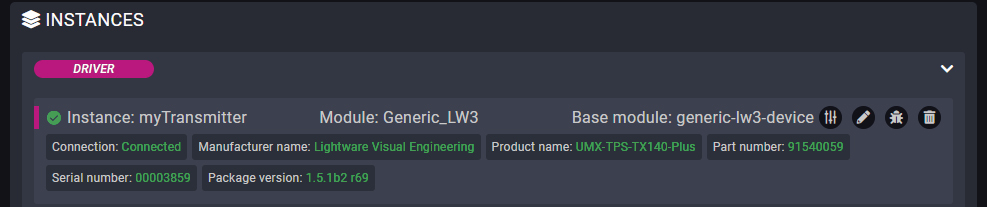
Defined Parameters
▪ipAddress
▪portNumber
They can be referred in the JavaScript code as e.g. params.ipAddress
Defined Events
▪connected: The LW3 device with the specified ipAddress is connected.
▪disconnected: The LW3 device with the specified ipAddress is disconnected.
▪LW3 property changed: The value of a specific LW3 property is changed to the defined value. 'path', 'property' and 'value' Parameters are defined in this Event.
Defined Methods
These methods can be used the same way as the ordinary LW3 GET, SET, OPEN, CLOSE and CALL commands.
▪get: Querying the value of a specific property (with path). 'path' and 'property' Parameters are defined in this Method. Example:
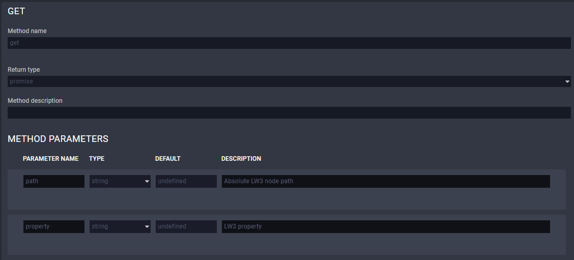
▪set: Setting the value of a specific writable property (with path). 'path', 'property' and 'value' Parameters are defined in this Method. Example:
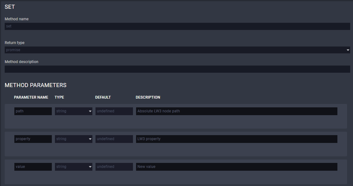
▪open: Subscribing to a specific node. It means that the user will get a notification if the property changes. 'path' Parameter is defined in this Method. Example:
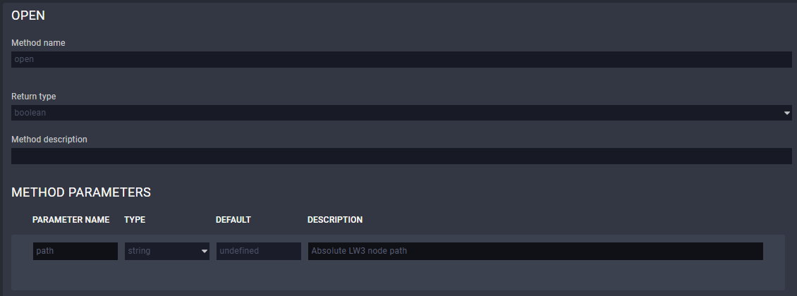
▪close: Unsubscribing from a specific node. 'path' Parameter is defined in this Method. Example:
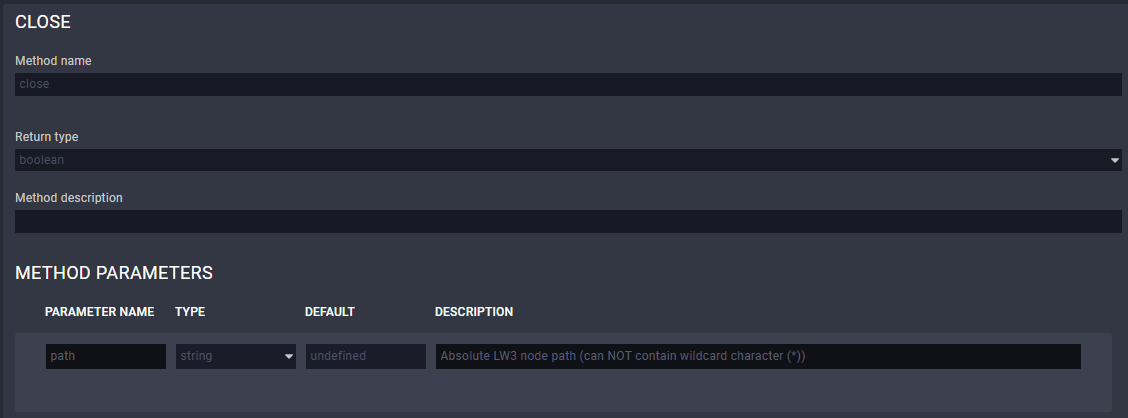
▪callMethod: Calling a specific LW3 Method; does not work for an LW3 property. 'path' and 'Method' Parameters are defined in this Method (Parameters are optional). Please note that wildchar (*) cannot be used in case of the 'path' Parameter. Example:
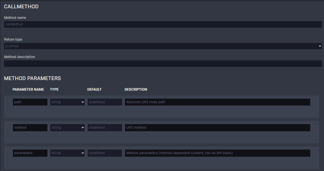
Defined Rules
No Rules are defined in this Module.
Custom Code
The code of the factory module in JavaScript.
ATTENTION!If the GUI tools cannot solve a problem, custom code can be added to the end of the code, but please note that if you upgrade the driver module (blue button) the custom sections will be deleted.
4.3. Taurus UCX/CTU/MMX2 Driver Module
Introduction
This Module is for controlling Lightware's UCX, DCX, MMX2 devices and the TPN-CTU-X50 conrol unit with a few Events and Methods. The Module covers the following models:
▪UCX-2x1-HC30
▪UCX-2x2-H30
▪UCX-4x2-HC30
▪UCX-4x2-HC30D
▪UCX-1x1-C40
▪UCX-2x1-HC40
▪UCX-2x2-H40
▪UCX-4x3-HC40
▪UCX-4x2-HC40
▪UCX-4x2-HC40D
▪UCX-1x1-C60
▪UCX-2x1-HC60
▪UCX-2x2-H60
▪UCX-4x3-HC60
▪UCX-4x2-HC60
▪UCX-4x2-HC60D
▪UCX-4x3-HC60-BD
▪UCX-4x3-TPX-TX20
▪UCX-2x1-TPX-TX20
▪UCX-3x3-TPX-RX20
▪UCX-4x3-TPN-TX20
▪UCX-2x1-TPN-TX20
▪MMX2-4x3-H20
▪MMX2-4x1-H20
▪DCX-2x1-HC10
▪DCX-3x1-HC20
▪DCX-3x1-HC21
▪TPN-CTU-X50
Dashbord Content
The following status indicators are displayed on the Status board in the row of the Instance:
▪Connection state of the device
▪Firmware package version
▪Product name
▪Overall health status
▪Outputs' source
▪Outputs' connection state
▪Outputs' signal presence
▪USB host input (if any)
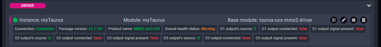
Defined Parameters
▪ipAddress
▪connectionType
=Raw TCP
=Websocket
=Secure Websocket
▪authenticationType
=no authentication
=basic authentication
▪username
▪password
They can be referred in the JavaScript code as e.g. params.ipAddress
Defined Events
▪connected: The UCX/CTU/MMX2 device with the specified ipAddress is connected.
▪disconnected: The UCX/CTU/MMX2 device with the specified ipAddress is disconnected.
▪sourceInputChanged: Another source is switched to the specified output. 'outoutPort' and 'sourcePort' Parameters are defined in this Event.
▪outputConnectedStatusChanged: Sink device is connected/disconnected to/from the specified output. 'outputPort' and 'status' Parameters are defined in this Event.
▪outputSignalPresentStatusChanged: The signal presence is changed on the specified output (e.g. signal is present/not present). 'outputPort' and 'status' Parameters are defined in this Event.
▪usbHostChanged: Another USB host device is selected for the USB peripherals. 'sourcePort' Parameter is defined in this Event to specify the USB input port.
▪overallHealthChanged: The value of the /V1/MANAGEMENT/HEALTH/OverallHealthState property is changed. 'healthStatus' Parameter is defined in the Event.
▪healthAlert: The value of a specific Parameter under /V1/MANAGEMENT/HEALTH node is changed to the defined value. 'property' and 'value' Parameters are defined in this Event.
▪LW3 property changed: The value of a specific LW3 property is changed to the defined value. 'path', 'property' and 'value' Parameters are defined in this Event.
Defined Methods
▪get: Querying the value of a specific property (with path). 'path' and 'property' Parameters are defined in this Method.
▪set: Setting the value of a specific writable property (with path). 'path', 'property'and 'value' Parameters are defined in this Method.
▪open: Subscribing to a specific node. It means that the user will get a notification if the property changes. 'path' Parameter is defined in this Method.
▪close: Unsubscribing from a specific node. 'path' Parameter is defined in this Method.
▪callMethod: Calling a specific LW3 Method; does not work for an LW3 property. 'path', 'Method' and 'Parameters' are defined in this Method (Parameters are optional.)
▪switchCrosspoint: Changing the crosspoint state of a specific layer (AUDIO, VIDEO or USB). Please note that USB is available only for specific models.
▪setGpioDirection: Setting the direction (input/output) of a specific GPIO pin. 'port' and 'direction' Parameters are defined in this Method.
▪setGpioState: Setting the state (low/high) of a specific GPIO pin. 'port' and 'state' Parameters are defined in this Method.
▪emulateEdid: Setting an EDID (source) to emulate on a specific input port (destination). 'source' and 'destination' Parameters are defined in this Method. Source can be: factory, dynamic, user. Destination can be: emulated.
▪uploadEdid: Uploading a HEX-format EDID to a User EDID slot. Target and data Parameters are defined in this Method.
▪changeAnalogAudioVolumeDB: Setting the volume level of a specific analog audio output in dB. 'port' and 'value' Parameters are defined in this Method.
▪changeAnalogAudioVolumePercent: Setting the volume level of a specific analog audio output in percentage. 'port'and 'value' Parameters are defined in this Method.
For further details about the LW3 properties or Methods, please see the User Manual of the device.
Defined Rules
No Rules are defined in this Module.
Custom Code
The code of the factory module in JavaScript.
ATTENTION!If the GUI tools cannot solve a problem, custom code can be added to the end of the code, but please note that if you upgrade the driver module (blue button) the custom sections will be deleted.
4.4. Taurus UCX-HCM Driver Module
Introduction
This module is for controlling Lightware's UCX devices equipped with dualscreen USB-C input port. Currently supported devices:
▪UCX-4x3-HCM40
Dashboard Content
The following status indicators are displayed on the Status board in the row of the instance:
▪Connection state of the device
▪FW package version
▪Product name
▪Overall health status
▪Dualscreen input status (number of video streams and technology)
▪Outputs' source
▪Outputs' connection state
▪Outputs' signal presence
Defined Parameters
▪ipAddress
▪connectionType
=Raw TCP
=Websocket
=Secure Websocket
▪authenticationType
=no authentication
=basic authentication
▪username
▪password
They can be referred in the JavaScript code as e.g. params.ipAddress
Defined Events
▪connected: The UCX/CTU/MMX2 device specified with the ipAddress is connected.
▪disconnected: The UCX/CTU/MMX2 device specified with the ipAddress is disconnected.
▪sourceInputChanged: Another source is switched to the spcified output. outoutPort and sourcePort parameters are defined in this event.
▪outputConnectedStatusChanged: Sink device is connected/disconnected to/from the specified output. outputPort and status parameters are defined in this event.
▪outputSignalPresentStatusChanged: The signal presence is changed on the specified output (e.g. signal is present/not present). outputPort and status parameters are defined in this event.
▪usbHostChanged: Another USB host device is selected for the USB peripherals. sourcePort parameter is defined in this event to specify the USB input port.
▪overallHealthChanged: The value of the /V1/MANAGEMENT/HEALTH/OverallHealthState property is changed. healthStatus parameter is defined in the event.
▪healthAlert: The value of a specific parameter under /V1/MANAGEMENT/HEALTH node is changed to the defined value. property and value parameters are defined in this event.
▪LW3 property changed: The value of a specific LW3 property is changed to the defined value. path, property and value parameters are defined in this event.
Defined Methods
▪get: Querying the value of a specific property (with path). path and property parameters are defined in this method.
▪set: Setting the value of a specific writable property (with path). path, property and value parameters are defined in this method.
▪open: Subscribing to a specific node. It means that the user will get a notification if the property changes. path parameter is defined in this method.
▪close: Unsubscribing from a specific node. path parameter is defined in this method.
▪callMethod: Calling a specific LW3 method; does not work for an LW3 property. path, method and parameters are defined in this method (parameters are optionally.)
▪switchCrosspoint: Changing the crosspoint state of a specific layer (AUDIO, VIDEO or USB. Please note that USB is available for specific models.) layer, source and destination parameters are defined in this method.
▪setGpioDirection: Setting the direction (input/output) of a specific GPIO pin. port and direction parameters are defined in this method.
▪setGpioState: Setting the state (low/high) of a specific GPIO pin. port and state parameters are defined in this method.
▪emulateEdid: Setting an EDID (source) to emulate on a specific input port (destination). source and destination parameters are defined in this method. Source can be: factory, dynamic, user. Destination can be: emulated.
▪uploadEdid: Uploading a hex-format EDID to a User EDID slot. target and data parameters are defined in this method.
▪changeAnalogAudioVolumeDB: Setting the volume level of a spefic analog audio output in DB. port and value parameters are defined in this method.
▪changeAnalogAudioVolumePercent: Setting the volume level of a spefic analog audio output in percentage. port and value parameters are defined in this method.
▪setDSPolicy: It sets the policy for Dualscreen USB-C input, whether to use DisplayLink, DisplayPort or decide automatically
▪setInputHpd: Enable or disable hotplug signal on inputs. When using in I1A / I1B inputs, the source will detect or not detect the distinct displays.
▪setInputHdcp: Enable or disable HDCP capabilities on input ports. When HDCP is disabled, sources will not be able to authenticate and send encrypted content.
4.5. Taurus CEC Driver Module
Introduction
This Module is for sending CEC commands (with REST API) to a sink (display) device connected to Lightware's UCX or MMX2 devices over HDMI output.
INFO:Since LARA cannot access to a hardware directly, the REST API interface is used for this purpose. That's why the TCP IP port number and physical connection is necessary for the communication.
Dashbord Content
The following status indicators are displayed on the Status board in the row of the Instance:
▪Connection state of the device
▪Controlled output port
▪Last CEC command timestamp (optional)
▪Last CEC command status (optional)

Defined Parameters
▪outputPort: Video output port of the UCX/MMX2 device for CEC command requests.
▪idlePollingFrequency: Time in seconds for CEC polling on output (0 = no idle polling).
▪ipAddressOrHost: The IP address or the host name of the device.
▪protocol: Protocol to be used for connection.
▪portNumber: Port number (80 for HTTP, 443 for HTTPS) to be used for connection.
▪authenticationType: Enable or disable basic authentication.
▪username: User name for basic authentication.
▪password: Password for basic authentication.
▪customHeaders: Setting custom headers with the following syntax: header-name:value.
▪cecMessageStats: Enable the last sent CEC message statistics on the Status Board.
▪debugMode: Enables the debug mode for sent CEC messages. All of the details of the messages will be printed to the console.
They can be referred in the JavaScript code as e.g. params.outputPort.
Defined Events
▪error: The CEC command sending was not successful.
▪availableOnCEC: The device responds to CEC REST requests.
▪unavailableOnCEC: Device do not respond to CEC REST requests.
Defined Methods
▪powerOn: Sending the Power On CEC command.
▪imageViewOn: Sending the Image View On CEC command (use this if the Power On command does not work).
▪powerOff: Sending the Power Off CEC command.
▪standby: Sending the Standby CEC command (use this if the Power Off command does not work).
▪mute: Sending the Mute CEC command.
▪unmute: Sending the Unmute CEC command.
▪volumeUp: Sending the Volume Up CEC command.
▪volumeDown: Sending the Volume Down CEC command.
▪customCommand: Sending a custom command via CEC. The command Parameter is defined for this purpose in this Method. The custom command can be a HEX string. Only hexadecimal characters are allowed, spaces can be used as delimiters.
Defined Rules
No Rules are defined in this Module.
Custom Code
The code of the factory module in JavaScript.
ATTENTION!If the GUI tools cannot solve a problem, custom code can be added to the end of the code, but please note that if you upgrade the driver module (blue button) the custom sections will be deleted.
4.6. Generic Rest Client Driver Module
Introduction
This Module is for handling REST API-based communication.
Dashbord Content
▪Last request timestamp: Last request status:

Defined Parameters
▪certAuthEnable: Enabling certificate-based authentication. Disable this when communicating with Lightware devices via HTTPS.
=true
=false
▪ipAddressOrHost: IP address or host name of device.
▪protocol: Protocol to be used for connection:
=HTTP
=HTTPS
▪portNumber: 80 for HTTP, 443 for HTTPS connection.
▪authenticationType:
=No authentication
=Basic authentication
▪username: user name for basic authentication.
▪password: password for basic authentication.
▪customHeaders: Setting custom headers with the following syntax: header-name:value.
They can be referred in the JavaScript code as e.g. params.username.
Defined Events
▪error
▪responseReceived
Defined Methods
▪put: PUT Method. Defined Parameters:
=path: string type
=Parameters: JSON type (optional)
=customHeaders: JSON type (optional)
▪post: POST Method. Defined Parameters:
=path: string type
=Parameters: JSON type (optional)
=customHeaders: JSON type (optional)
▪get: GET Method. Defined Parameters:
=path: string type
=Parameters: JSON type (optional)
=customHeaders: JSON type (optional)
▪del: DEL Method. Defined Parameters:
=path: string type
=Parameters: JSON type (optional)
=customHeaders: JSON type (optional)
Defined Rules
No Rules are defined in this Module.
Custom Code
The code of the factory module in JavaScript.
ATTENTION!If the GUI tools cannot solve a problem, custom code can be added to the end of the code, but please note that if you upgrade the driver module (blue button) the custom sections will be deleted.
4.7. TPN-MMU Driver Module
DIFFERENCE:The module is built in LARA v2.0.0 only.
Introduction
This Module is for controlling Lightware's TPN-MMU-X100 series matrix management unit with LW3 protocol commands including a few Events and Methods. The Module covers the following models:
▪TPN-MMU-X100
▪TPN-MMU-X100-20
Dashbord Content
The following status indicators are displayed on the Status board in the row of the Instance:
▪Connection state of the device
▪Manufacturer name
▪Product name
▪Part number
▪Serial number
▪Firmware package version
![[Alt text was not generated.]](UM-web-resources/image/LARA_StatusBoard_MMUDriver.png)
Defined Parameters
▪ipAddress
▪portNumber
They can be referred in the JavaScript code as e.g. params.ipAddress
Variables
▪clientConnected: Indicates whether the LW3 client managed to connect to the desired Lightware device.
Defined Events
▪connected: The MMU with the specified ipAddress is connected.
▪disconnected: The MMU with the specified ipAddress is disconnected.
▪LW3 property changed: The value of a specific LW3 property is changed to the defined value. 'path', 'property' and 'value' Parameters are defined in this Event.
▪LW3 GET response received: A response has been received for a request.
▪signalPresentChanged: Signal present property has been changed on one of the input/output port of an endpoint device.
▪crosspointChanged: A crosspoint setting has been changed.
Defined Methods
These methods can be used the same way as the ordinary LW3 GET, SET, OPEN, CLOSE and CALL commands.
▪get: Querying the value of a specific property (with path). 'path' and 'property' Parameters are defined in this Method.
▪set: Setting the value of a specific writable property (with path). 'path', 'property' and 'value' Parameters are defined in this Method.
▪open: Subscribing to a specific node. It means that the user will get a notification if the property changes. 'path' Parameter is defined in this Method.
▪close: Unsubscribing from a specific node. 'path' Parameter is defined in this Method.
▪callMethod: Calling a specific LW3 Method; does not work for an LW3 property. 'path' and 'Method' Parameters are defined in this Method (Parameters are optional). Please note that wildchar (*) cannot be used in case of the 'path' Parameter.
▪getStreams: Querying the value of the available streams properties in the TPN/OPTN matrix on the network. 'path' and 'property' Parameters are defined in this Method.
▪getSignalPresent: Querying the value of the signal present properties in the endpoint devices. 'path' and 'property' Parameters are defined in this Method.
▪switchCrosspoint: Calling the switch(<source>,<destination>) LW3 method (with path) to change the crosspoint settings. 'path' and 'Method' Parameters are defined in this Method (Parameters are optional). Please note that wildchar (*) cannot be used in case of the 'path' Parameter.
Defined Rules
No Rules are defined in this Module.
Custom Code
The code of the factory module in JavaScript.
ATTENTION!If the GUI tools cannot solve a problem, custom code can be added to the end of the code, but please note that if you upgrade the driver module (blue button) the custom sections will be deleted.
ATTENTION!The module can be used up to 20 endpoint devices.
Introduction
This Module is for discovering Lightware's TPN, OPTN and UCX-TPN devices on the network, and controlling them with a few Events and Methods. The Module covers the following models:
▪TPN-CTU-X50
▪UCX-2x1-TPN-TX20
▪UCX-4x3-TPN-TX20
The Module supports discovering and managing the following SDVoE-based endpoint models on the network:
▪UCX-2x1-TPN-TX20
▪UCX-4x3-TPN-TX20
▪HDMI-TPN-TX107
▪HDMI-TPN-TX207AU2K
▪HDMI-TPN-RX107
▪HDMI-TPN-RX107AU2K
▪HDMI-TPN-RX107A-SR
▪HDMI-TPN-RX107AU2K-SR
▪HDMI-OPTN-TX100A
▪HDMI-OPTN-TX200AU2K
▪HDMI-OPTN-RX100A
▪HDMI-OPTN-RX100AU2K
▪HDMI-OPTN-RX100A-SR
▪HDMI-OPTN-RX100AU2K-SR
Dashboard Content
The following status indicators are displayed on the Status board in the row of the Instance:
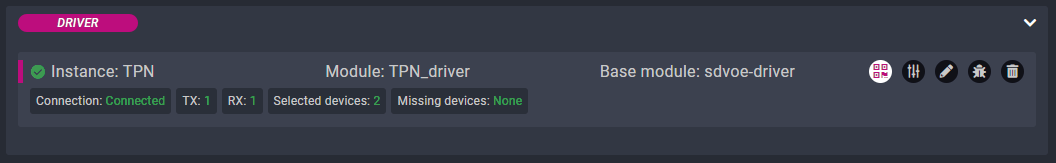
▪Connection
▪TX
▪RX
▪Selected devices
▪Missing devices
Defined Parameters
▪connectionType
=Raw TCP
=Websocket
=Secure Websocket
▪ipAddressOrHost: IP address or host name of device.
▪portNumber: 80 for HTTP, 443 for HTTPS connection.
▪clientConnected: Indicates if there is an active connection with the SDVoE Control Server.
▪txCount: The number of TX devices
▪rxCount: The number of RX devices
▪selectedDevicesCount: The number of selected devices.
▪missingDevices: The missing device(s).
Defined Events
▪sdvoeDisconnected: SDVoE Control Server is disconnected.
▪sdvoeConnected: SDVoE Control Server is connected.
▪deviceVideoSwitched: Crosspoint has been changed.
▪deviceAudioSwitched: Crosspoint has been changed.
▪deviceConnected: Connected a new SDVoE device.
▪deviceDisconnected: SDVoE device is disconnected.
▪userpanelSettingsChanged: Userpanel Settings changed.
Defined Methods
▪switch: Switch a transmitter to a receiver. If the transmitter is already connected to a receiver, it will be disconnected first.
▪leave: Will remove one or more connections.
▪join: Will join a transmitter to a receiver on a given layer. Layer can be 'HDMI' or 'HDMI_AUDIO'.
▪logAllDevices: Log all available devices on the network to the debug output.
▪getDeviceList: For internal use in communicating with the user panel. Returns the selected devices on the network.
▪getConnections: For internal use in communicating with the user panel. Returns the connections of the selected devices on the network.
Defined Rules
No Rules are defined in this Module.
Custom Code
The code of the factory module in JavaScript.
ATTENTION!If the GUI tools cannot solve a problem, custom code can be added to the end of the code, but please note that if you upgrade the driver module (blue button) the custom sections will be deleted.
4.9. Icron USB 2.0 Driver Module
ATTENTION!The module can be used up to 20 endpoint devices.
Introduction
This Module is for discovering Lightware's UCX-TPN extenders and -U2K series (Icron USB 2.0) endpoint devices on the network and controlling them with a few Events and Methods. The Module covers the following models:
▪TPN-CTU-X50
▪UCX-2x1-TPN-TX20
▪UCX-4x3-TPN-TX20
The Module supports discovering and managing the following Icron-based endpoint models on the network:
▪UCX-2x1-TPN-TX20
▪UCX-4x3-TPN-TX20
▪HDMI-TPN-TX207AU2K
▪HDMI-TPN-RX107AU2K
▪HDMI-TPN-RX107AU2K-SR
▪HDMI-OPTN-TX200AU2K
▪HDMI-OPTN-RX100AU2K
Dashboard Content
The following status indicators are displayed on the Status board in the row of the Instance:
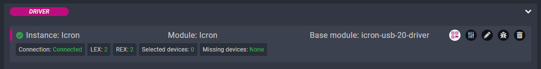
▪Connection
▪LEX
▪REX
▪Selected devices
▪Missing devices
Defined Parameters
▪pollingInterval: How often to poll the device for status (ms). 5000 is the recommended value.
Status Variables
▪clientConnected: Indicates if there is an active connection.
▪txCount: The number of LEX devices
▪rxCount: The number of REX devices
▪selectedDevicesCount: The number of selected devices.
▪missingDevices: The missing device(s).
Defined Events
▪connected: ICRON is connected.
▪disconnected: ICRON is disconnected.
▪switched: Will be fired when a change is detected in the pairings of a LEX.
▪deviceAudioSwitched: Crosspoint has been changed.
▪deviceConnected: Device has been connected.
▪deviceDisconnected: Device has been disconnected.
Defined Methods
▪switch: Switch a LEX to a REX, while all other connections are removed from the LEX.
▪leave: Will disconnect two devices. If the second parameter is not provided, it will disconnect all devices from the first one.
▪join: Will connect two devices.
▪logAllDevices: Intended for debug usage. It will list all devices.
▪setStreamOptimizationMode: Set the stream optimization mode: None/SUI/MSA.
▪getStreamOptimizationMode: Get the stream optimization mode: None/SUI/MSA.
▪getDeviceList: For internal use in communicating with the user panel. Returns the selected devices on the network.
▪getConnections: For internal use in communicating with the user panel. Returns the connections of the selected devices on the network.
Defined Rules
No Rules are defined in this Module.
Custom Code
The code of the factory module in JavaScript.
ATTENTION!If the GUI tools cannot solve a problem, custom code can be added to the end of the code, but please note that if you upgrade the driver module (blue button) the custom sections will be deleted.
4.10. Cisco Webex Script Module
DIFFERENCE:This module description is valid for LARA v1.3.0b5 and above only.
INFO:The module supports the Cisco Webex and Microsoft Teams Rooms (MTR) services either.
Supported Cisco Devices
The following Cisco devices are supported by this Module:
▪Cisco Room Kit
▪Cisco Room Kit Mini
▪Cisco Room Kit Plus
▪Cisco Room Kit Pro
▪Cisco Codec Plus
▪Cisco Codec Pro
▪Cisco Desk Pro
▪Cisco Room 70 G2
▪Cisco Telepresence SX20
▪Cisco Telepresence SX80
▪Cisco DX70
▪Cisco DX80
▪Cisco MX700
▪Cisco MX800
▪Cisco Room Bar
▪Cisco Room Bar Pro
▪Cisco Room Kit EQ
▪Cisco Board Pro
Supported Lightware Devices
Fully compatible and tested Lightware devices:
▪UCX-2x1-HC30
▪UCX-2x2-H30
▪UCX-4x2-HC30
▪UCX-4x2-HC30D
▪UCX-1x1-C40
▪UCX-2x1-HC40
▪UCX-2x2-H40
▪UCX-4x3-HC40
▪UCX-4x2-HC40
▪UCX-4x2-HC40D
▪UCX-4x3-HC40-BD
▪UCX-4x3-HCM40
▪MMX2-4x3-H20
▪MMX2-4x1-H20
▪UCX-4x3-TPX-TX20
▪UCX-2x1-TPX-TX20
▪UCX-4x3-TPN-TX20
▪UCX-2x1-TPN-TX20
Compatible, but not tested Lightware devices:
▪DCX-2x1-HC10
▪DCX-3x1-HC20
▪UCX-3x3-TPX-RX20
Not compatible Lightware device (due to no built-in AV input and output ports):
▪TPN-CTU-X50
Module Description
Cisco Integration script provides connection and source expansion integration with Cisco videoconferencing devices.
Changelog - v1.3.2
▪Fixed - Codec update required restarting the LARA or Taurus in case of RS232 integration fixed.
▪Fixed - Download of Taurus support package caused stop of the integration fixed.
▪Fixed - New virtual codec inputs caused error messages in the logs fixed.
▪Fixed - Taurus TPX integration via remote serial port communication issues.
▪Added - Methods and events for for logic modules to issue codec commands and configurations beside retrieve status and event feedbacks.
Changelog - v1.2.1
▪Fixed - Integration issues with Cisco Room Kit Mini fixed.
▪Fixed - Issues with Cisco codec control using Taurus RS-232 serial port fixed.
▪Changed - Integration parameter names and options changed based on integrators' feedbacks for better understanging.
Defined Events
▪Codec MTR Detected: Codec MTR Detected.
▪UserInterface Extensions Widget Action: UserInterface Extensions Widget Action happened.
▪CallDisconnect: Call was disconnected.
▪IncomingCallIndication: Incoming call indication.
▪OutgoingCallIndication: Outgoing call indication.
▪UserInterface Extensions Event PageClosed: Page closed on UserInterface.
▪UserInterface Extensions Panel Clicked: Panel clicked on UserInterface.
▪UserInterface Presentation ExternalSource Selected: Presentation ExternalSource selected.
▪UserInterface Extensions Event Pressed: UserInterface Extensions Pressed event happened.
▪Video Output Connector: Video output connector status changed.
▪Video Input Connector: Video input connector status changed.
▪Standby State: Standby State status changed.
▪Message Send: Message sent by Message Send command has been received.
▪Audio Volume: Audio Volume changed.
▪Audio Volume Mute: Audio Volume Mute status changed.
▪Audio Microphones Mute: Audio Microphones Mute status changed.
▪UI Panel Saved: UI Panel Saved
▪LARA Connected Status: LARA - Cisco Codec Connected Status changed.
▪LARA Cisco Error In Connection: LARA Cisco Communication Error Happened In Connection.
INFO:For your own custom project, you shall set/use methods and events.
Expandable Module
More supplementary modules can be added to the Cisco Webex Script module for the most customized user experience and for advanced usebility, e.g. Room Control Module. Visit the LARA product page and select the File Downloads tab and explore the downloadable supplementary modules.
The Purpose of This Module
The following main benefits can be achieved by using Taurus/MMX2 devices and LARA with this Module:
Bring Your Own Device (BYOD) mode: adding inputs to the Cisco Codec: thus more video sources (e.g. laptops) can be shared.
Camera share option: using the high quality camera and audio system of the Codec for other meeting purposes like a Zoom, Teams, etc. conference for a connected PC/laptop. It extends and expands source capabilities with content sharing and accessing room peripherals.
BYOD Mode
Cisco Codecs usually contain only one HDMI input. It can be increased by connecting a Taurus UCX device to that input port, thus up to four devices can be connected. Furthermore, certain Taurus models contain USB-C ports, allowing another connection type. When video signal is detected on a video input port of the Taurus device, it will be visible on the UI of the Codec. After that the source can be selected as a BYOD source. Each input can be labelled with a unique name to display in the UI of the Codec.
Camera Share Option
It may happen that a video conference is taking place not via the Webex service, but with one of the particpant's laptop. The camera and the audio system of the Codec is much more suitable for this purpose than a laptop, so this feature means the camera and the audio devices can be shared to a PC/laptop connected over HDMI and USB-B or only USB-C.
4.10.1. Integrating Over Serial Connection
This chapter is about the settings when the Taurus and the Codec are connected via Serial port.
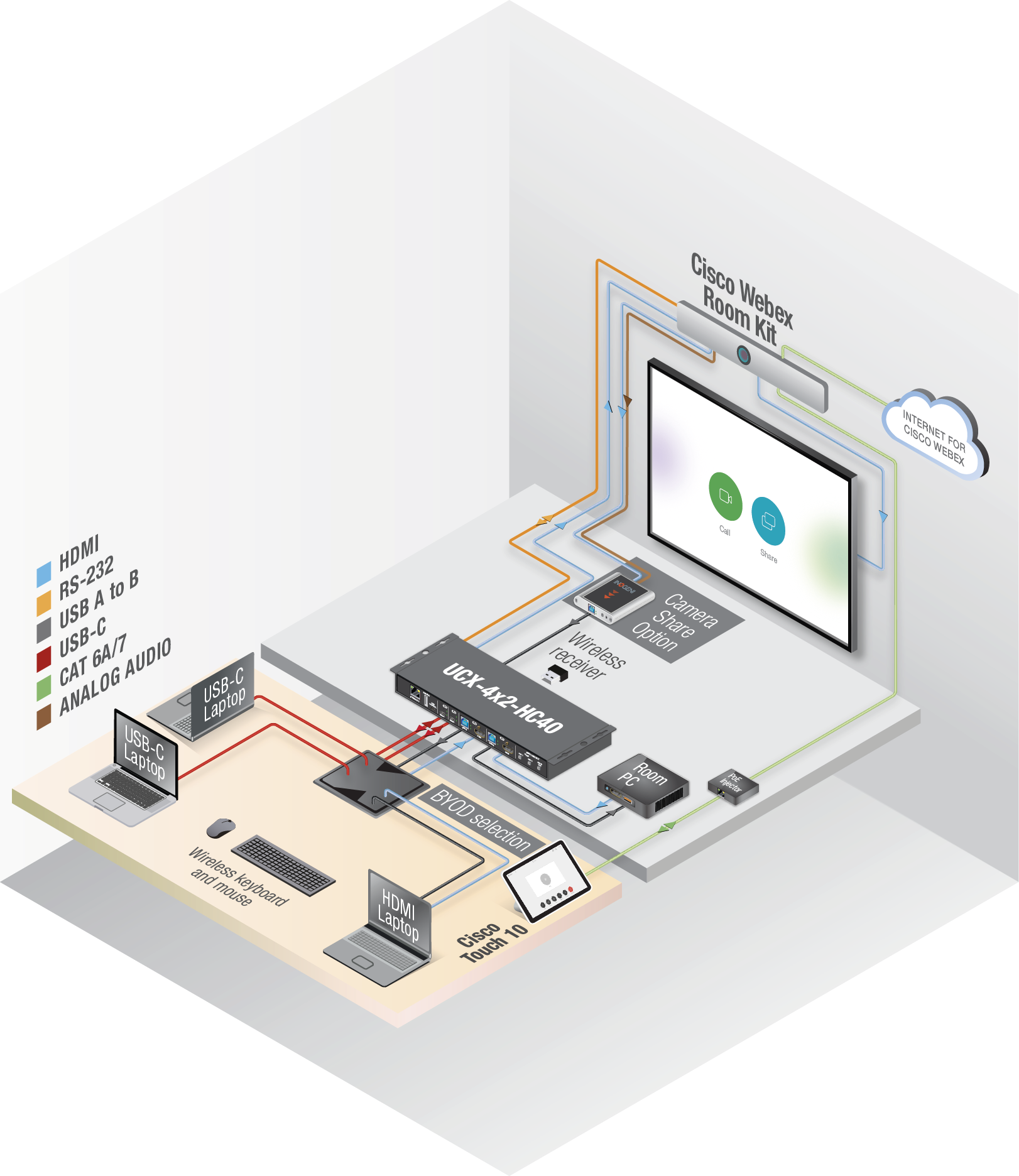
Checklist for the Taurus/MMX2 Device
ATTENTION!The module is designed for factory default settings of the Taurus/MMX2 device. If the Lightware device is not in factory default state, please use this checklist to ensure the flawless working of the Cisco module.
Before connecting and configuring the Taurus to a Cisco Codec, the following have to be checked:
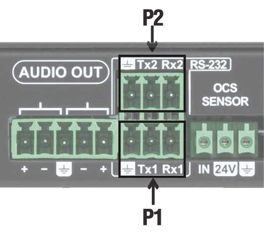
▪Make sure the autoselect is disabled on the video output ports as well as on USB ports.
▪Check if the Serial over IP port is enabled: 8001 for P1, 8002 for P2 and 8003 for P3 (LDC/Settings/Services).
▪Set the Video and USB-C ports to umuted and unlocked state.
▪Pay attention to the physical serial port: use the port where the cable is connected to.
Checklist for the Codec
▪The serial port settings must match in the Taurus and in the Codec.
▪Create a user name and set a password in the Codec. (Note them, these should be entered when configuring the module in LARA.)
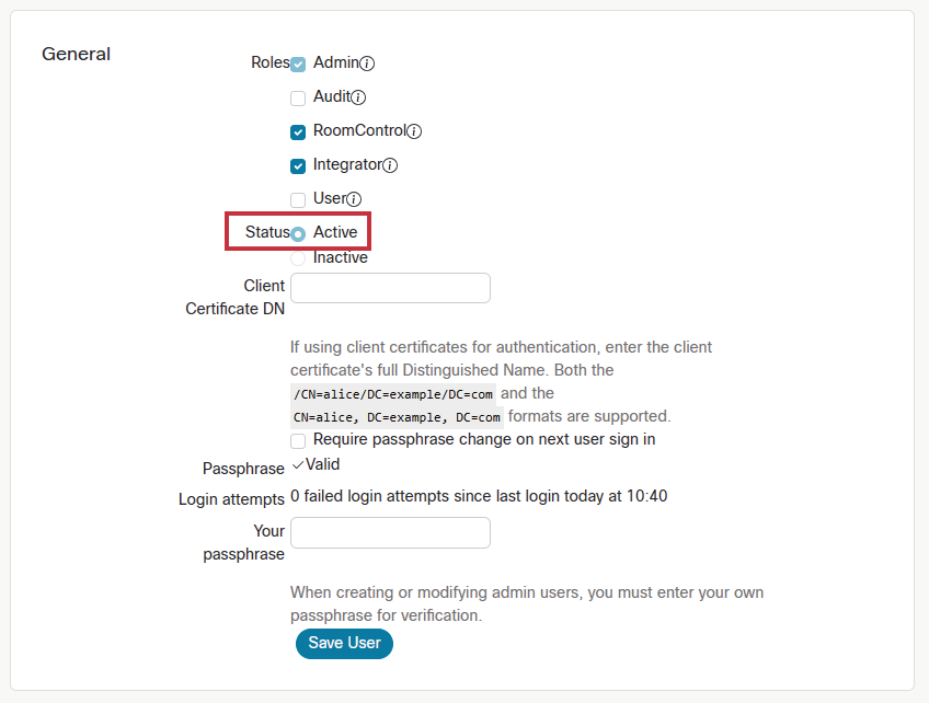
▪Privileges should be enabled for:
=RoomControl,
=Integrator,
=Admin.
▪The following option shall be disabled:
=Require passphrase change on next user sign in.
▪If you install a USB capture device for camera share, e.g. Inogeni 4KXUSB3, connect it to the last HDMI output of the Codec.
INFO:Certain Cisco codecs do not have separate RS-232 port, but the dedicated USB port can be used for this purpose. In that case, connect a USB-Serial (FTD) cable between the Taurus and the Codec.
Instance Parameters
Create an Instance from the module 'ciscowebex' and set the instance parameters as follows:
ATTENTION!Do not leave the value of the parameter in 'empty' state if it can be selected from a drop-down menu.
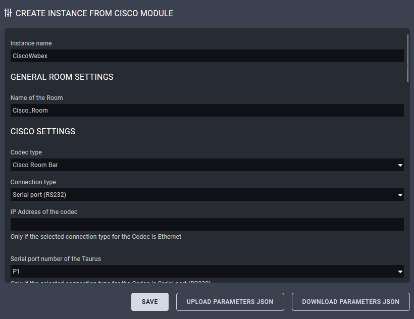
Instance Name and Name of the Room
Set them as you wish. Use only ISO basic Latin alphabet characters in the names.
Codec Type
Select the Cisco model you install.
Connection Type
Select Serial port (RS232).
INFO:Ethernet connection is not required between the Taurus and the Codec in case of serial connection.
IP Address of the Cisco Device
Type the IP address of the connected Cisco device.
Serial Port Number of the Taurus
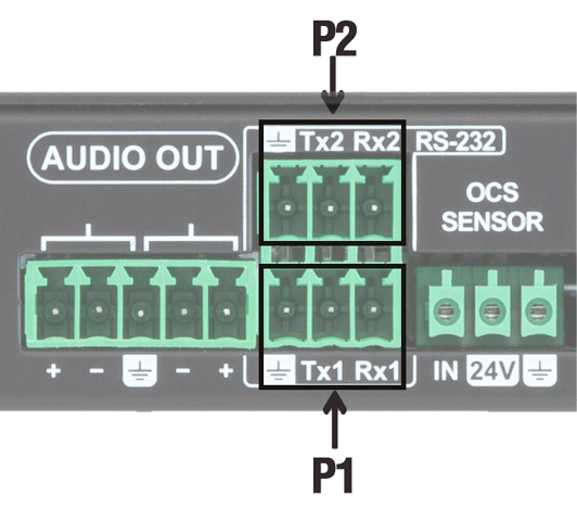
Select the serial port number from the drop-down list.
TIPS AND TRICKS:In case of Taurus switchers (H40/HC40 series) and MMX2 switchers the serial port means the P1 or P2 ports. If the actual devices are Taurus extenders (TPX/TPN series) and the connected serial port is on the receiver side, the port numbers will be the following: in case of UCX-2x1-TPX-TX20 and UCX-2x1-TPN-TX20 the serial port is the P2; in case of UCX-4x3-TPX-TX20 and UCX-4x3-TPN-TX20 the serial port is the P3.
Username for Cisco Codec Connection
As set in the Codec previously.
Password for Cisco Codec Connection
As set in the Codec previously.
Cisco Codec Output Port Connection Settings (#1/#2/#3)
DIFFERENCE:The available port numbers are Codec-dependent.
▪If you have a display device connected to a certain output, set it to 'Display'.
▪If you connect a USB capture device to the last HDMI output for camera share option, set the 'USB capture device'. In this case the Output connection setting on that output does not matter.
▪Set 'No connection' for the output that is not used.
Taurus Input Port Settings
Set the inputs (source labels on Cisco touch panel) that will be visible on the Cisco UI (BYOD selection). If you leave a field empty, the input will not be placed to the UI as a source. ASCII characters (space also) are accepted.
ATTENTION!For Cisco-compatibility reasons the HDCP will be disabled on the inputs that are defined in the BYOD selection.
Taurus Settings - Outputs
Select which output port of the Taurus UCX / MMX2 is connected to which input port of the Cisco codec.
Presentation Mode
Manual (default): Manual interaction needed to present your connected source via tapping on the Navigator's Share Screen and tap on view or present to have the conencted source's content on screen or in call to far end.
AutoShare: When there is an active video signal then the codec automatically selects the connected source to present on the screen (no need to tap on Share Screen list). OnConnect: When there is a new connection on the codec input then it shares the content on screen.)
Share Video Input Connector Visibility
Always (default): Presents all the configured external source labels to stay in the Share Screen list.
IfSignal: Presents those sources only in the the Share Screen list which has active incoming video signal.
Enable BYOD Pop-Up on Source Connection
Recommended setting for Room Kit Mini, Room Bar, Room Bar Pro and Room EQ: No
Enable BYOD Panel Creation
Auto: do not create when Cisco Room Device has USB-C connection, create otherwise.
Yes: create
No: do not create
MonitorRole Setting
MonitorRole setting for capture card output. Options: Automatic (default) setting, First, Second, Third, No setting.
Enable Debug Mode
If enabled every incoming message and outgoing message will be logged to the console.
4.10.2. Integrating Over Secure Websocket (WSS) Connection
This chapter is about the settings when the Taurus and the Codec are connected via websocket secure Ethernet (WSS).
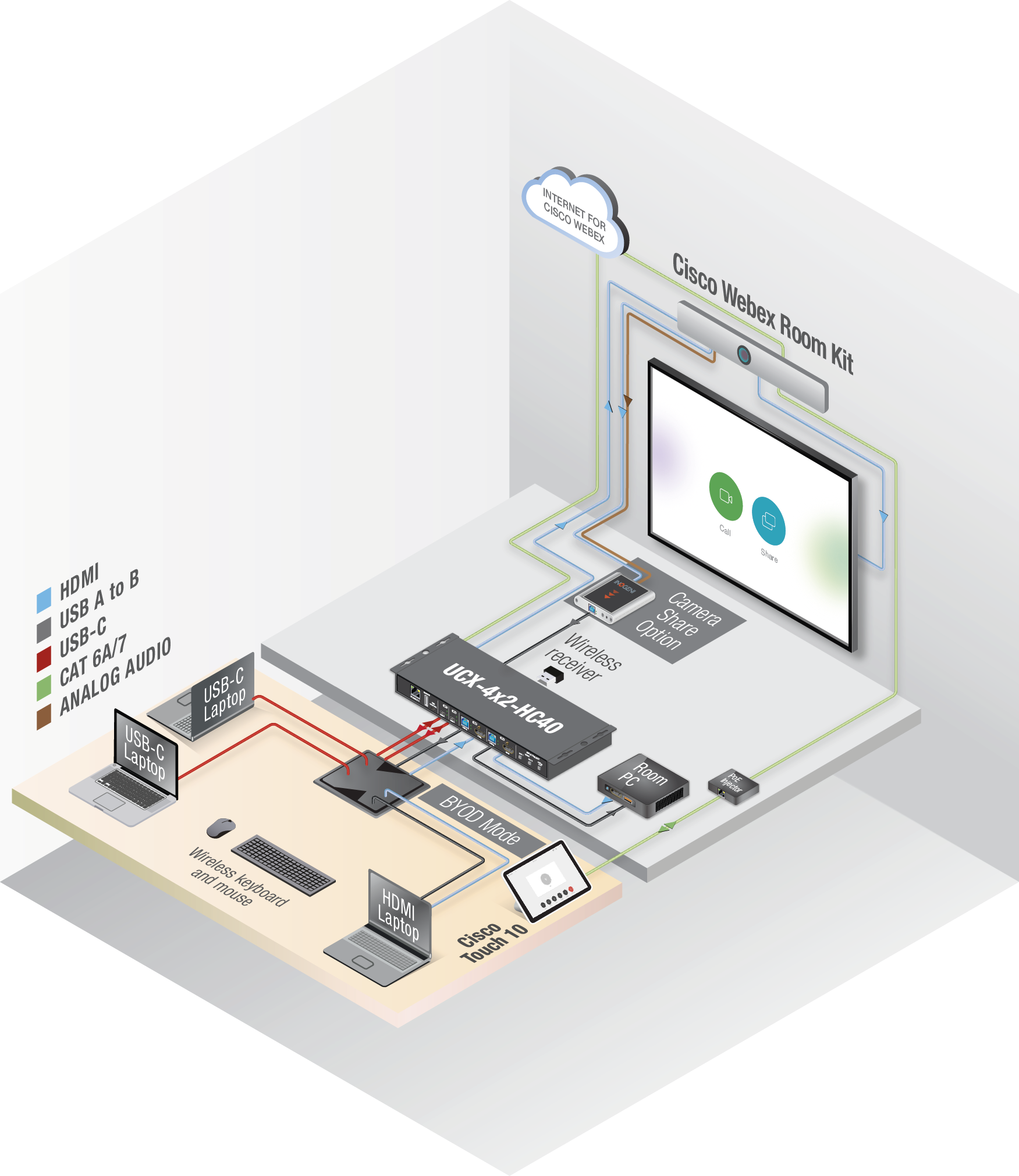
Checklist for the Taurus/MMX2 Device
ATTENTION!The module is designed for factory default settings of the Taurus/MMX2 device. If the Lightware device is not in factory default state, please use this checklist to ensure the flawless working of the Cisco module.
▪Make sure that the Taurus and the Codec can communicate with each other over Ethernet.
▪Check the VLAN preset settings of the Taurus (Control/Ethernet page in LDC): the Codec and the MCU must be in the same VLAN.
▪Make sure the autoselect is disabled on the video output ports as well as on USB ports.
▪Set the Video and USB-C ports to umuted and unlocked state.
Checklist for the Codec
▪Websocket has to be enabled (the integration works with wss (secured websocket) communication). Open the Codec web interface:
=Settings Configurations NetworkServices Websocket FollowHTTPService.
=Settings Configurations NetworkServices HTTP Mode HTTPS.
=Save the settings.
▪Create a user name and set a password in the Codec. (Note them, these should be entered when configuring the Module in LARA.)
▪Privileges should be enabled for:
=RoomControl,
=Integrator,
=Admin.
▪The following option shall be disabled:
=Require passphrase change on next user sign in.
▪If you install a USB capture device for camera share, e.g. Inogeni 4XKUSB3, connect it to the last HDMI output of the Codec.
Instance Parameters
Create an Instance from the Module 'ciscowebex' and set the Instance Parameters as follows:
ATTENTION!Do not leave the value of the Parameter in 'empty' state if it can be selected from a drop-down menu.
![[Alt text was not generated.]](UM-web-resources/image/CiscoWebex_Ethernet_Parameters.png)
Instance Name and Name of the Room
Set them as you wish. Use only ISO basic Latin alphabet characters in the names.
Codec Type
Select the Cisco model you install.
Connection Type
Select Websocket.
Connection Restart Timeout
The default value is 5000 milisecs waited before the module restarts after an error.
IP Address of the Cisco Device
Type the IP address of the Codec.
Serial Port Number of the Taurus
N/A
Username for Cisco Codec Connection
As set in the Codec previously.
Password for Cisco Codec Connection
As set in the Codec previously.
Cisco Codec Output Port Connection Settings (#1/#2/#3)
DIFFERENCE:The available port number is Codec-dependent.
▪If you have a display device connected to a certain output, set it to 'Display'.
▪If you connect a USB capture device to the last HDMI output for camera share option, set the 'Last HDMI Output as USB Capture' setting to 'true'. In this case the Output connection setting on that output does not matter.
▪Set 'no connection' for the output that is not used.
Taurus Settings
The default settings work, no need to change.
Taurus Input Port Settings
Set the labels that will be visible on the Cisco UI (BYOD selection). If you leave a field empty, that input will not be placed to the UI as a source. ASCII characters (space also) are accepted.
ATTENTION!For Cisco-compatibility reasons the HDCP will be disabled on the inputs that are defined in the BYOD selection.
Taurus Settings - Outputs
Select which output port of the Taurus UCX / MMX2 is connected to which input port of the Cisco codec.
Presentation Mode
Manual (default): Manual interaction needed to present your connected source via tapping on the Navigator's Share Screen and tap on view or present to have the conencted source's content on screen or in call to far end.
AutoShare: When there is an active video signal then the codec automatically selects the connected source to present on the screen (no need to tap on Share Screen list). OnConnect: When there is a new connection on the codec input then it shares the content on screen.)
Share Video Input Connector Visibility
Always (default): Presents all the configured external source labels to stay in the Share Screen list.
IfSignal: Presents those sources only in the the Share Screen list which has active incoming video signal.
Enable BYOD Pop-Up on Source Connection
Recommended setting for Room Kit Mini, Room Bar, Room Bar Pro and Room EQ: No
Enable BYOD Panel Creation
Auto: do not create when Cisco Room Device has USB-C connection, create otherwise. Yes: create; No: do not create.
MonitorRole Setting
MonitorRole setting for capture card output. Options: Automatic (default) setting, First, Second, Third, No setting.
Enable Debug Mode
If enabled every incoming message and outgoing message will be logged to the console.
4.10.3. Further Notices
Webex Mode
Webex mode is activated if:
▪The Codec is started, or
▪All devices are disconnected from the Codec.
INFO:Half Wake and Standby modes are active in Webex mode, but in BYOD mode these modes are inactive.
After Restart
If the Codec, the UCX/MMX2 or LARA is restarted for some reason, the system must recover in the same working state as it has been previously.
4.10.4. Known Issues
'Preset does not exist'
This message may appear in the log window when the Codec is a Cisco Room Kit Mini. This entry does not mean an error.
'Unknown widget: 'byodselector'
This message may appear in the log window when the Codec is a Cisco Room Kit Mini. This entry does not mean an error.
For camera sharing option
Please connect the USB capture device (or the RoomKit Mini USB-C cable) to the Taurus port USB-A #1:
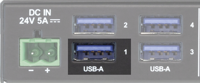
Unused Button
It may happen in case of Room Kit Mini and Room Kit Bar Codecs that the UI contains a button with the following label: 'Call from laptop'. This button has no function in this case.
4.10.5. Integration with the Cisco Codec
INFO:The Cisco Webex Script Module is compatible with Cisco Webex, Microsoft Teams Rooms (MTR) systems as well.
Main Menu
After a successful setup, the Cisco codec is ready to integrate the inputs and outputs of the Taurus UCX / MMX2 switchers and extenders.
INFO:The sample screenshots show the Cisco Webex (left) and the MTR systems (right) side by side with the same functionality.
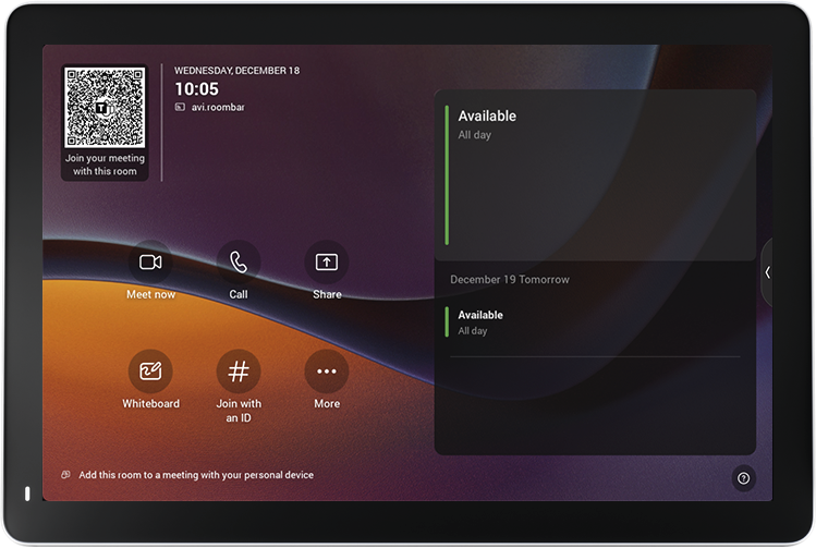
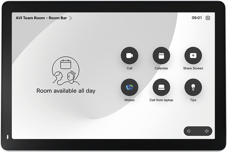
Source Selection
Cisco Webex (left): select the Share Screen button for the screen sharing menu.
MTR (right): swipe the menu bar on the right side to left to access the extended options of screen sharing.
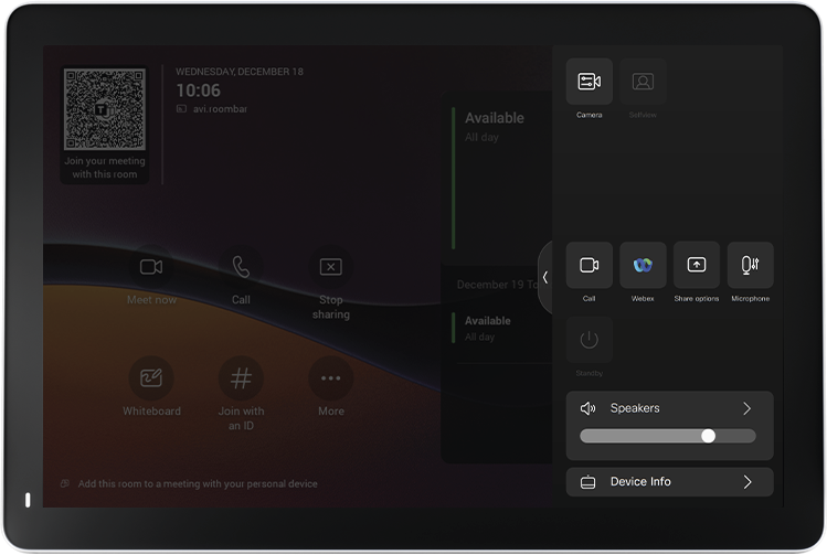
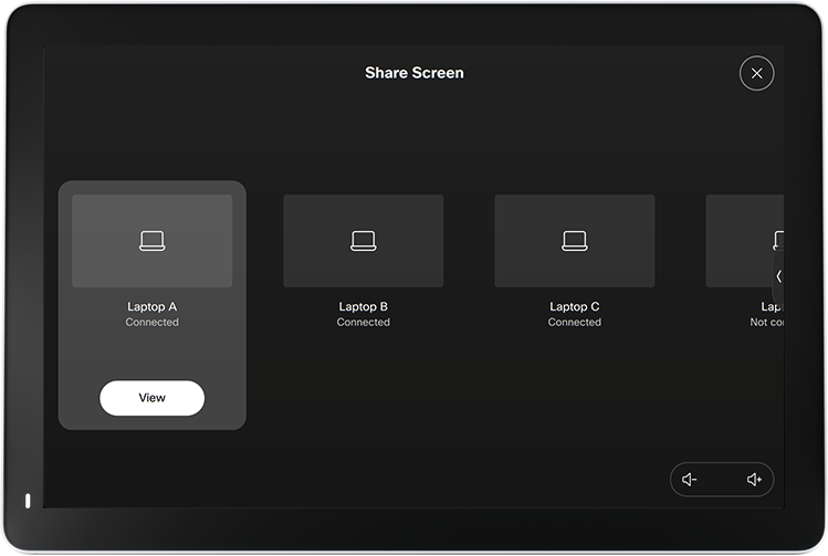
Select the wished share source.
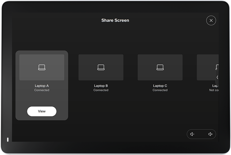
The screen sharing is working over the Taurus UCX / MMX2 device..
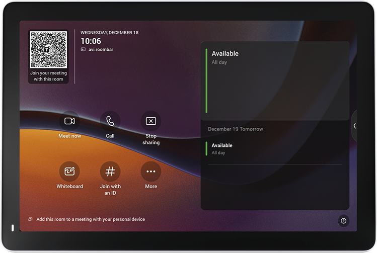
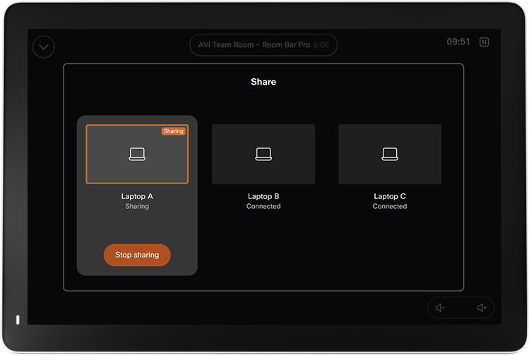
Touch 10
DIFFERENCE:The following description is valid for the Touch 10 and older meeting room systems only.
Main Menu
After a successful setup a new button will appear in the Main menu of the Codec: BYOD Selection.
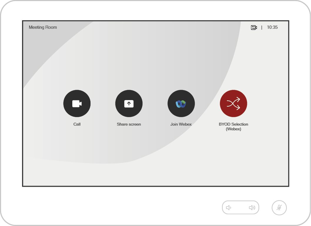
BYOD Selection
ATTENTION!The BYOD selection is valid for the older Touch 10 system only. This option is highly not recommended for Room Navigator and MTR systems.
After pressing the 'BYOD Selection' button, a window appears on the UI of the Codec. On the bottom of the screen the defined and available inputs can be seen with the labels set in the Instance *.
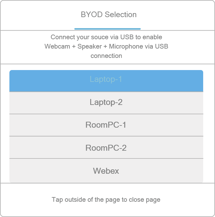
* If there is no USB layer in the Lightware device, the label below the 'BYOD selection' is: 'Connect your source via HDMI'.
When a source is selected:
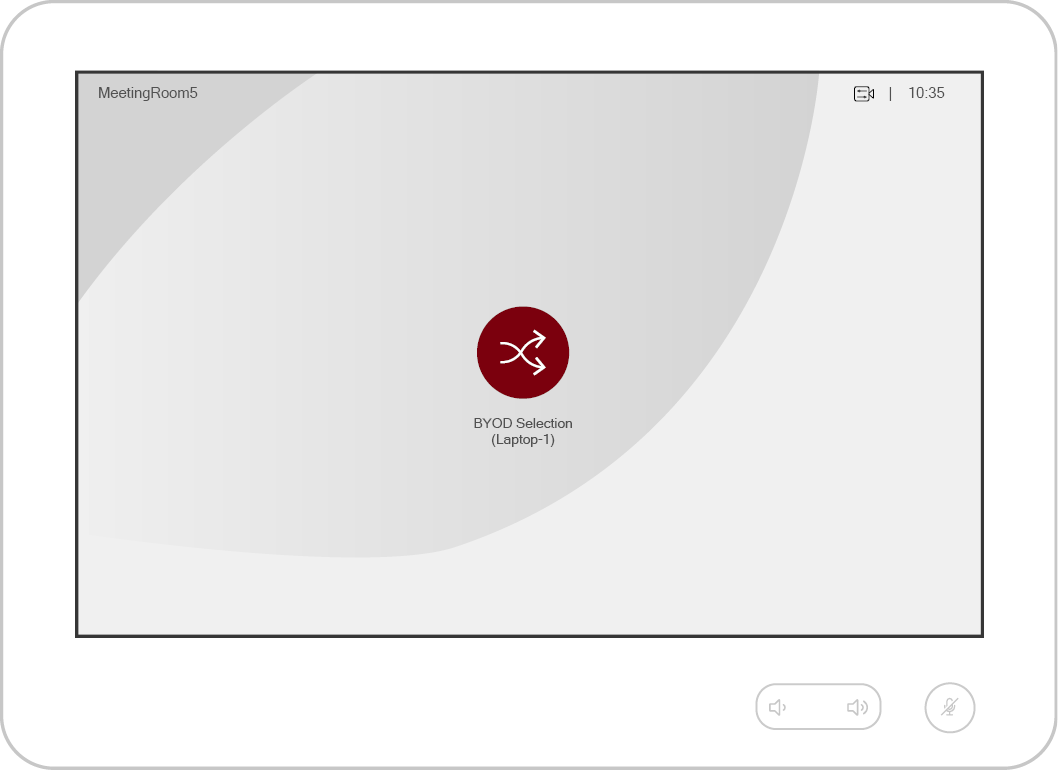
▪The video signal of the selected source is displayed on all outputs of the Codec except the last HDMI output if a USB capture device is installed on that port.
▪Not applicable buttons will be hidden in the main menu.
▪The USB crosspoint of the Taurus UCX device will follow the video crosspoint state if the 'Enable USB parallel switching' option is 'true'.
▪The 'SpeakerTrack' feature of the camera is turned on – if it is supported.
▪The microphone signal will be sent via the analog audio output of the Codec to the USB capture device. *
▪The 'Do not disturb' mode of the Codec will be switched on with default timeout (24 h).
▪The automatic standby mode is deactivated in the Codec.
When selecting 'Webex' again:
▪The video output of the Codec will be the default UI content.
▪Previously hidden buttons will appear again in the menu.
▪The 'SpeakerTrack' feature of the camera will be still on – if it is supported.
▪The analog audio output of the Codec will be switched off. *
▪The 'Do not disturb' mode of the Codec will be switched off.
▪The 'Halfwake' mode must be activeted in the Codec after 2 minutes of idle time.
* Does not refer to Cisco Webex Room Kit Mini.
If a new source is connected to the UCX/MMX2 device, the following window appears:
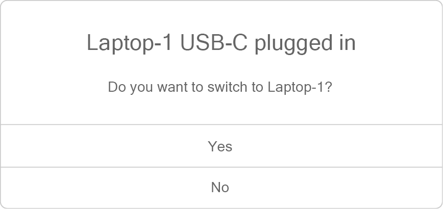
4.11. Sink Driver Modules
ATTENTION!The following modules can be applied in the LARA v2.0.0 only.
Sink devices from different brands can be controlled with the following driver modules:
▪NEC displays - see the details in the NEC Driver Module section.
▪Sony Bravia televisions - see the details in the Sony Bravia Driver Module section.
▪Samsung Signage displays - see the details in the Samsung Signage Display Driver section.
▪Philips displays - see the details in the Philips Display Driver section.
▪Panasonic displays - see the details in the Panasonic Display Driver section.
ATTENTION!The module can be applied in the LARA v2.0.0 only.
Introduction
This Module is for controlling the NEC displays with a few Events and Methods.
Dashboard Content
The following status indicators are displayed on the Status board in the row of the Instance:
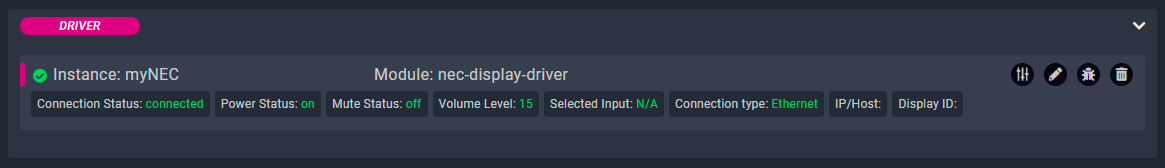
▪Connection
▪Power status
▪Mute status
▪Volume level
▪Selected input
▪Connection type
▪IP/Host
▪Display ID
Defined Parameters
▪ConnectionRelatedSettings: Connection related settings.
▪displayAddress: Display ID, Display Id 1 - 100, default is 1.
▪controlType: Connection type to the display - TCP/IP over Ethernet, or RS232 serial.
▪ipAddressOrHost: IP address or hostname to use when connecting to the display via Ethernet TCP/IP and local IP address of the UCX when using RS232 connection.
▪portNumber: Port to use when connecting to the display via Ethernet TCP/IP. Protocol default value: 7142
▪wolsettings: Wake On LAN settings.
▪macAddress: MAC Address for wakeOnLan method (in 11:22:33:44:55:66 format).
▪serialSettings: Serial connection settings
▪ucxPort: UCX serial port, P1 (default), P2 or P3.
Status Variables
▪inputStatus: Tracks the selected input of the display.
▪volumeStatus: Tracks the volume level of the display.
▪powerStatus: Tracks the power status of the display (ON/OFF).
▪muteStatus: Tracks the mute status of the display.
▪clientConnected: Indicates if there is an active TCP connection with the device.
Defined Events
▪frameReceived
Defined Methods
▪broadcastCommand: Sends command string built from 1 command byte and data bytes to all the displays accessible via the connection. NEC Control manual for available commands and command data.
▪sendGroupCommand: Sends command string built from 1 command byte and data bytes to group of displays using group identifier (groupId). NEC Control manual for available commands and command data.
▪sendCommand: Sends command string built from 1 command byte and data bytes. NEC Control manual for available commands and command data.
▪wakeOnLan: If a MAC address is present, the driver tries to send the Wake on LAN command to the display
▪powerOff: Sends the powerOff command to the display.
▪powerOn: Sends powerOn command to the display, or WakeOnLan command in case the WOL MAC Address parameter is present.
▪setVolume: Sets the volume level to a given value between 0-100.
▪volumeDown: Sends the volumeDown command to the display's speaker, decrementing its volume level by 1.
▪volumeUp: Sends the volumeUp command to the display's speaker, incrementing the volume level by 1.
▪unMute: Sends the unMute audio coommand.
▪mute: Sends the mute audio command.
▪selectInput: Sends a command to select the given input on the display:
▪getInputStatus: Updates the input status variable.
▪getMuteStatus: Updates the mute status variable.
▪getPowerStatus: Updates the power status variable.
▪getVolumeStatus: Updates the volume status variable.
Defined Rules
No Rules are defined in this Module.
Custom Code
The code of the factory module in JavaScript.
ATTENTION!If the GUI tools cannot solve a problem, custom code can be added to the end of the code, but please note that if you upgrade the driver module (blue button) the custom sections will be deleted.
4.11.2. Sony Bravia Driver Module
ATTENTION!The module can be applied in the LARA v2.0.0 only.
Introduction
This Module is for controlling the Sony Bravia displays with a few Events and Methods.
Dashboard Content
The following status indicators are displayed on the Status board in the row of the Instance:
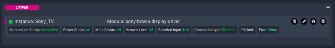
▪Connection
▪Power status
▪Mute status
▪Volume level
▪Selected input
▪Connection type
▪IP/Host
▪Error
Defined Parameters
▪ConnectionRelatedSettings: Connection related settings.
▪controlType: Connection type to the display - TCP/IP over Ethernet, or RS232 serial.
▪ipAddressOrHost: IP address or hostname to use when connecting to the display via Ethernet TCP/IP and local IP address of the UCX when using RS232 connection.
▪portNumber: Port to use when connecting to the display via Ethernet TCP/IP. Protocol default value: 20060
▪serialSettings: Serial connection settings
▪ucxPort: UCX serial port, P1 (default), P2 or P3.
Status Variables
▪connectionStatus: Tracks the connected status of the display. Valid values: connected, disconnected.
▪inputStatus: Tracks the selected input of the display. Valid values: HDMI1, HDMI2, INPUT3, INPUT4.
▪volumeLevel: Tracks the volume level of the display. Valid values are between 0 and 100.
▪powerStatus: Tracks the power status of the display. Valid values: on, off.
▪muteStatus: Tracks the mute status of the display. Valid values: on, off
Defined Events
▪connectionStatusUpdated: Returns the connection status of the display.
▪powerStatusUpdated: Returns the power status of the display.
▪muteStatusUpdated: Returns the mute status of the display.
▪volumeUpdated: Returns the volume level of the display.
▪inputStatusUpdated: Returns the selected input name of the display.
▪frameReceived: Returns the received reply from the display.
Defined Methods
▪sendCommand: Sends command string. Please refer to Sony Bravia manual for available commands and command data.
▪powerOff: Switch off the display.
▪powerOn: Switch on the display.
▪setVolume: Sets the volume level to a given value between 0-100.
▪volumeDown: Decrease the volume by 1.
▪volumeUp: Increase the volume by 1.
▪unMute: Unmute audio.
▪mute: Mute audio.
Defined Rules
No Rules are defined in this Module.
Custom Code
The code of the factory module in JavaScript.
ATTENTION!If the GUI tools cannot solve a problem, custom code can be added to the end of the code, but please note that if you upgrade the driver module (blue button) the custom sections will be deleted.
4.11.3. Samsung Signage Display Driver
ATTENTION!The module can be applied in the LARA v2.0.0 only.
Introduction
This Module is for controlling the Samsung Signage displays with a few Events and Methods.
Dashboard Content
The following status indicators are displayed on the Status board in the row of the Instance:
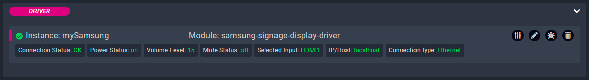
▪Connection
▪Power status
▪Volume level
▪Mute status
▪Selected input
▪IP/Host
▪Connection type
Defined Parameters
▪ConnectionRelatedSettings: Connection related settings.
▪displayAddress: 1 - 254, 255 will control all connected displays regardless of their IDs
▪controlType: Connection type to the display - TCP/IP over Ethernet, or RS232 serial.
▪ipAddressOrHost: IP address or hostname to use when connecting to the display
▪wolsettings: Wake On LAN settings.
▪macAddress: MAC Address for wakeOnLan method (in 11:22:33:44:55:66 format).
▪serialSettings: Serial connection settings
▪ucxPort: UCX serial port, P1 (default), P2 or P3.
Status Variables
▪inputStatus: Tracks the selected input of the display.
▪volumeStatus: Tracks the volume level of the display.
▪powerStatus: Tracks the power status of the display (ON/OFF).
▪muteStatus: Tracks the mute status of the display.
▪clientConnected: Indicates if there is an active TCP connection with the device.
Defined Events
▪frameReceived
Defined Methods
▪startStatusPolling: Sends get status command to the Display every 10 seconds.
▪stopStatusPolling: Stops periodic status polling towards the Display.
▪getInputStatus: Updates the input status variable.
▪getMuteStatus: Updates the mute status variable.
▪getPowerStatus: Updates the power status variable.
▪getVolumeStatus: Updates the volume status variable.
▪getDisplayStatus: Sends get status command to the Display.
▪selectInput: Sends a command to select the given input on the display:
▪unMute: Sends the unMute audio command.
▪mute: Sends the mute audio command.
▪setVolume: Sets the volume level to a given value between 0-100.
▪volumeDown: Sends volume down command to the Display.
▪volumeUp: Sends volume up command to the Display.
▪powerOff: Sends the powerOff command to the display.
▪powerOn: Sends powerOn command to the display, or WakeOnLan command in case the WOL MAC Address parameter is present.
▪sendCommand: Method to send custom command to Samsung Signage Display using Hexadecimal format.
▪wakeOnLan: Sends wake on lan to Display if target MAC address is defined.
▪broadcastMessage: Method to send custom command to Samsung Signage Displays using Hexadecimal format. This command will use DisplayID 0xFE. Displays will not respond.
Defined Rules
No Rules are defined in this Module.
Custom Code
The code of the factory module in JavaScript.
ATTENTION!If the GUI tools cannot solve a problem, custom code can be added to the end of the code, but please note that if you upgrade the driver module (blue button) the custom sections will be deleted.
4.11.4. Philips Display Driver
ATTENTION!The module can be applied in the LARA v2.0.0 only.
Introduction
This Module is for controlling the Philips displays with a few Events and Methods.
Dashboard Content
The following status indicators are displayed on the Status board in the row of the Instance:
▪Connection status
▪Display ID
▪Group ID
▪Power status
▪Mute status
▪Volume level
▪Selected input
▪Connection type
▪IP/Host
▪Connection type
▪MAC address
▪Error
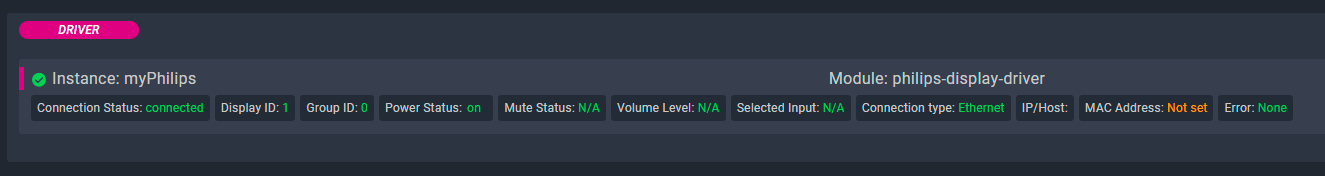
Defined Parameters
▪controlType: Connection type to the display - TCP/IP over Ethernet, or RS232 serial.
▪ipAddressOrHost: IP address or hostname to use when connecting to the display via Ethernet TCP/IP and local IP address of the UCX when using RS232 connection.
▪portNumber: Port to use when connecting to the display via Ethernet TCP/IP. Protocol default value: 5000.
▪ucxPort: UCX serial port, P1 (default), P2 or P3.
▪macAddress: MAC address.
▪displayId: This parameter is used to set the monitor ID.
▪groupId: This parameter is used to set the monitor group ID.
▪statusPollingInterval: Status Polling Interval (ms).
Status Variables
▪connectionStatus: Tracks the connected status of the display. Valid values: connected, disconnected.
▪powerStatus: Tracks the power status of the display. Valid values: on, off.
▪muteStatus: Tracks the mute status of the display. Valid values: on, off.
▪volumeLevel: Tracks the volume level of the display. Valid values are between 0 and 100.
▪inputStatus: Tracks the selected input of the display. Valid values: HDMI1, HDMI2, DVI.
Defined Events
▪connectionStatusUpdated: Returns the connection status of the display.
▪powerStatusUpdated: Returns the power status of the display.
▪muteStatusUpdated: Returns the mute status of the display.
▪volumeUpdated: Returns the volume level of the display.
▪inputStatusUpdated: Returns the selected input name of the display.
▪frameReceived
Defined Methods
▪wakeOnLan: If a MAC address is present the driver tries to send the Wake on LAN command 20to the display.
▪sendCommand: Sends command string. Please refer to Philips manual for available commands and command data.
▪powerOff: Sends the powerOff command to the display.
▪powerOn: Sends the powerOn command to the display.
▪setVolume: Sets the volume level to a given value between 0-100.
▪volumeDown: Sends the volumeDown command to the display's speaker, decrementing its volume level by 1.
▪volumeUp: Sends the volumeUp command to the display's speaker, incrementing the volume level by 1.
▪unMute: Sends the unmute audio coommand.
▪mute: Sends the mute audio command.
▪selectInput: Sends a command to select the given input on the display.
▪getInputStatus: Updates the input status variable.
▪getMuteStatus: Updates the mute status variable.
▪getPowerStatus: Updates the power status variable.
▪getVolumeStatus: Updates the volume status variable.
Defined Rules
No Rules are defined in this Module.
Custom Code
The code of the factory module in JavaScript.
ATTENTION!If the GUI tools cannot solve a problem, custom code can be added to the end of the code, but please note that if you upgrade the driver module (blue button) the custom sections will be deleted.
4.11.5. Panasonic Display Driver
ATTENTION!The module can be applied in the LARA v2.0.0 only.
Introduction
This Module is for controlling the Samsung Signage displays with a few Events and Methods.
Dashboard Content
The following status indicators are displayed on the Status board in the row of the Instance:
▪Connection
▪Power status
▪Mute status
▪Volume level
▪Selected input
▪Connection type
▪IP/Host
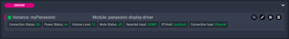
Defined Parameters
▪controlType: Connection type to the display - TCP/IP over Ethernet, or RS232 serial.
▪ipAddressOrHost: IP address of the UCX when using RS232 connection.
▪portNumber: Port to use when connecting to the display via Ethernet NTCONTROL. Protocol default value: 1024.
▪ucxPort: UCX serial port, P1 (default), P2 or P3.
▪labelNTControlAuth: NTCONTROL authentication settings.
▪userName: Web Control Administrator-Authorized User name.
▪password: Password for the above Administrator-Authorized User.
Status Variables
▪connectionStatus: Tracks the connected status of the display. Valid values: connected, disconnected.
▪inputStatus: Tracks the selected input of the display. Valid values: HDMI1, HDMI2, HDMI3, PC, USB.
▪volumeLevel : Tracks the volume level of the display. Valid values are between 0 and 100.
▪powerStatus: Tracks the power status of the display. Valid values: on, off.
▪muteStatus: Tracks the mute status of the display. Valid values: on, off.
Defined Events
▪connectionStatusUpdated: Returns the connection status of the display.
▪powerStatusUpdated: Returns the power status of the display.
▪muteStatusUpdated: Returns the mute status of the display.
▪volumeUpdated: Returns the volume level of the display.
▪inputStatusUpdated: Returns the selected input name of the display.
▪frameReceived
Defined Methods
▪sendCommand: Sends command string. Please refer to Panasonic EQ3 control manual for available commands and command data.
▪powerOff: Switch off the display.
▪powerOn: Switch on the display.
▪setVolume: Sets the volume level to a given value between 0-100.
▪volumeDown: Decrease the volume by 1.
▪volumeUp: Increase the volume by 1.
▪unMute: Unmute audio.
▪mute: Mute audio.
▪selectInput: Select the given input on the display. Valid values:HDMI1,HDMI2,INPUT3,PC,USB.
▪getInputStatus: Updates the input status variable.
▪getMuteStatus: Updates the mute status variable.
▪getPowerStatus: Updates the power status variable.
▪getVolumeStatus: Updates the volume status variable.
4.12. Network Communication Protocol Modules
ATTENTION!The following modules are not included in LARA by default, but they can be downloaded from the dedicated LARA website and applied to the local Lightware device.
4.12.1. SSH Client Driver
Introduction
Driver module for controlling a third-party device via SSH protocol.
Status Variables
▪clientConnected: Indicates if the client is connected with the device.
▪lastReceivedFrame: Contains the value of the last received frame.
▪lastReceivedFrameBytes: Contains the value of the last received frame bytes as Uint8Array.
▪lastReceivedFrameHex: Contains the value of the last received frame as hexadecimal encoded string.
Defined Events
▪connected: Emitted once the socket is connected and authentication is successful.
▪disconnected: Socket disconnected.
▪closed: Socket closed.
▪error: An error occured.
▪frameReceived: Emitted when the client received data from the server.
Defined Methods
▪send: Sends a string message.
▪sendFrame: Sends a string message with the frame delimiter appended to the end.
▪sendHex: Sends a message as per character based hexadecimal coded string.
▪end: Disconnects the socket.
4.12.2. TCP Server Driver
Introduction
Generic module for creating TCP server.
Status Variables
▪listening: TCP server is running.
Defined Events
▪ready: Server is ready to receive connections.
▪received: Server received data from a client.
▪connected: Client established connection.
▪error: Server error.
▪clientError: Client error.
▪dropped: Server dropped connection due to reaching maxConnections limit.
▪disconnect: Client disconnected from server.
▪closed: TCP server is closed.
▪published: Message was broadcasted to all clients.
▪sent: Message was sent to a client.
Defined Methods
▪address: Returns the AddressInfo of the TCP server.
▪close: Shuts down the TCP server.
▪publish: Broadcasts message to all clients.
▪send: Writes message to specified socket.
▪listen: Starts TCP server.
4.12.3. Telnet Client Driver
Introduction
Generic module for handling Telnet based communication.
Status Variables
▪isConnected: Telnet client is connected.
Defined Events
▪connected: Emitted when a socket connection is successfully established.
▪data: This is a forwarded 'data' event from core 'net' library.
▪timeout: Emitted if the socket times out from inactivity. This is only to notify that the socket has been idle. The user must manually close the connection.
▪failedlogin: Emitted when the failedLoginMatch pattern is provided and a match is found from the host. The 'destroy()' method is called directly following this event.
▪closed: Emitted once the socket is fully closed.
▪end: Emitted when the other end of the socket (remote host) sends a FIN packet.
▪error: Emitted when an error occurs. The 'close' event will be called directly following this event.
Defined Methods
▪connect: Conncets to the server.
▪send: Sends data on the socket without requiring telnet negotiations.
▪close: Half-closes the socket. i.e., it sends a FIN packet. It is possible the server will still send some data.
▪destroy: Ensures that no more I/O activity happens on this socket. Only necessary in case of errors (parse error or so).
4.12.4. UDP Client Driver
Introduction
Driver module for controlling a third-party device via UDP protocol.
Status Variables
▪isConnected: Indicates if there is an active UDP connection with the device.
▪isBound: Indicates if the socket is listening for data.
▪isClosed: Indicates if the socket is stopped listening for data.
▪lastReceivedData: Contains the value of the last received data.
▪lastReceivedDataBytes: Contains the value of the last received frame bytes as Uint8Array.
▪lastReceivedDataHex: Contains the value of the last received data as hexadecimal encoded string.
Defined Events
▪connected: Emitted once the socket is associated to a remote address.
▪listening: Emitted once the socket is addressable and can receive data.
▪messageSent: Emitted once the message is sent.
▪dataReceived: Emitted once the socket has received data.
▪disconnected: Socket disconnected.
▪closed: Socket closed.
▪error: An error occured.
Defined Methods
▪connect: Connects the socket to a remote host and port.
▪bind: Causes the socket to listen for datagram messages on a specified port and address. Without calling this method, the operating system will attempt to listen on 0.0.0.0 and on a random port.
▪send: Sends a string message whether the socket is connected or not.
▪sendHex: Sends a message as per character based hexadecimal coded string whether the socket is connected or not.
▪disconnect: Disconnects the socket from the remote endpoint.
4.12.5. Websocket Client Driver
Introduction
Generic module for handling WebSocket based communication.
Status Variables
▪clientConnected: Indicates if there is an active WebSocket connection with the device.
Defined Events
▪connected
▪disconnected
▪message
▪error
Defined Methods
▪send
▪disconnect
▪reconnect
4.12.6. Wake-on-LAN Driver
Introduction
Driver module for managing Wake-on-LAN requests.
Status Variables
▪lastWakeRequestResult: Result of the last wake request.
▪lastWakeRequestMacAddress: MAC address of the last wake request.
Defined Events
▪wakeRequested: A wake request occurred.
▪error: An error occured.
Defined Methods
▪requestWakeWithConfirmation: Request to wake a device with a given MAC address and IP address. Ping the device after wake request to confirm that it is accessible. Returns true if the device is accessible.
▪requestWake: Request to wake a device with a given MAC address without confirmation. Returns true if the request is sent.
This chapter is about the Touchscreen UI Module that has been developed by Lightware. The properties and the configuration steps are described in the coming sections.
5.1. Module Templates
Introduction
The Module offers ready-to-use user interface templates for touchscreen devices, which provide controlling various type of meeting or huddle rooms.
Designs
▪2 different design sets
▪Apply each design set for all above templates
Devices
The default templates contains the following devices and control tools:
▪Room: On / Off
▪Camera: Move Up / Down / Right / Left / Zoom in / Zoom out
▪Microphone: Mute / Unmute
▪Display: Turn on / Turn off
▪Volume: Increase / Decrease
▪Lights: On / Off
TIPS AND TRICKS:The built-in templates can be customized freely and users can add new buttons and features to the touchpanel as well. See more personalization samples in the Personalizing of the UI section.
5.1.1. Huddle Room Template
Devices in the template:
▪Room
▪Camera
▪Microphone
▪Display
▪Volume slider
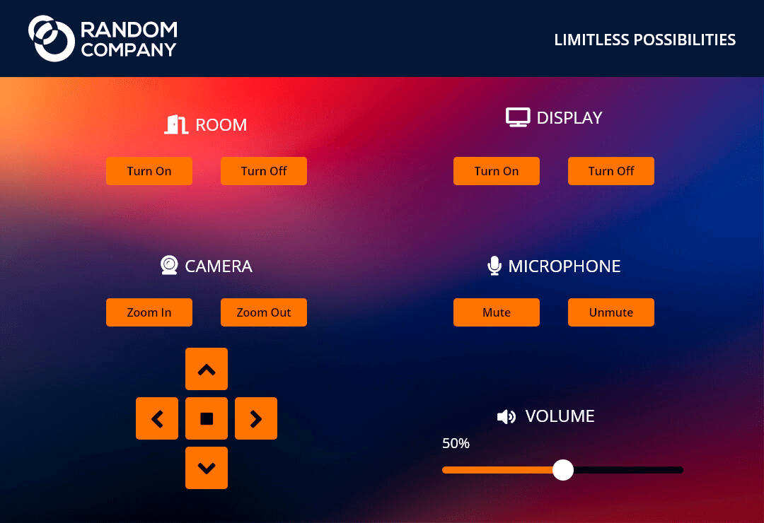
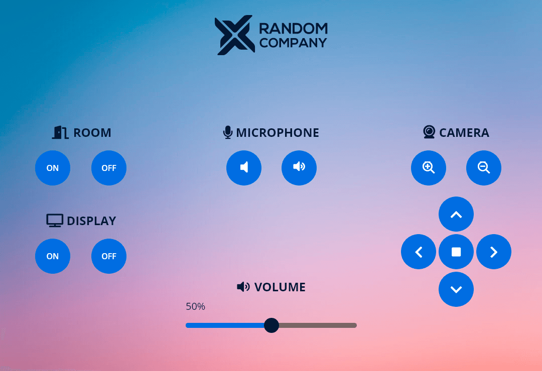
5.1.2. Meeting Room Template
Devices in the template:
▪Room
▪Camera
▪Microphone
▪Two displays
▪Volume slider
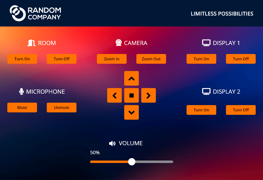
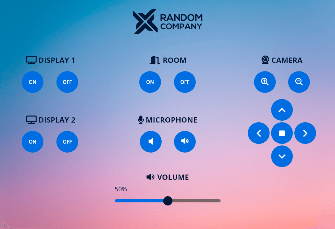
5.1.3. Meeting Room with Light Control Template
Devices in the template:
▪Room
▪Camera
▪Microphone
▪Two displays
▪Volume slider
▪Light
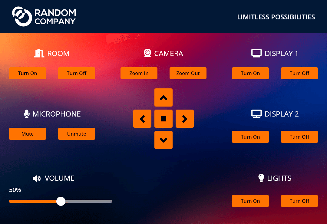
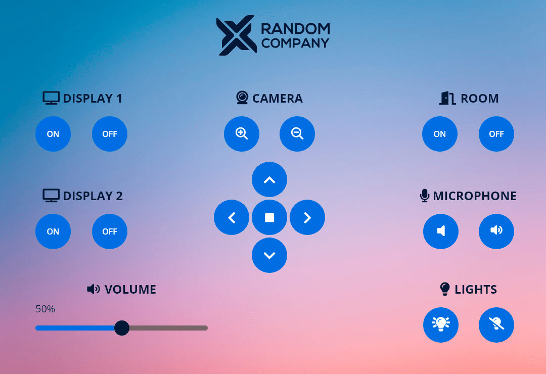
5.1.4. TPN Small Room Template
The template is recommended to use as the dedicated user interface for the SDVoE Driver Module.
Tools in the template:
▪Crosspoint view for the TPN and OPTN AV matrix.
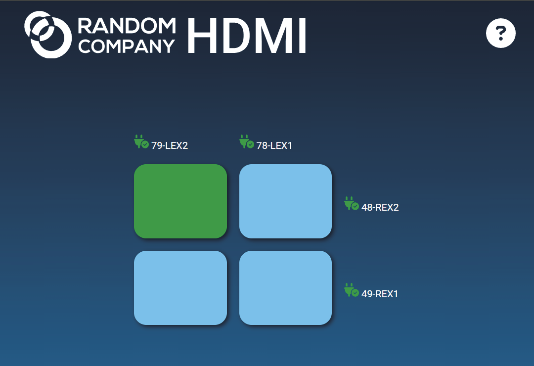
5.1.5. Icron Small Room Template
The template is recommended to use as the dedicated user interface for the Icron USB 2.0 Driver Module.
Tools in the template:
▪Crosspoint view for the Icron USB 2.0 matrix.
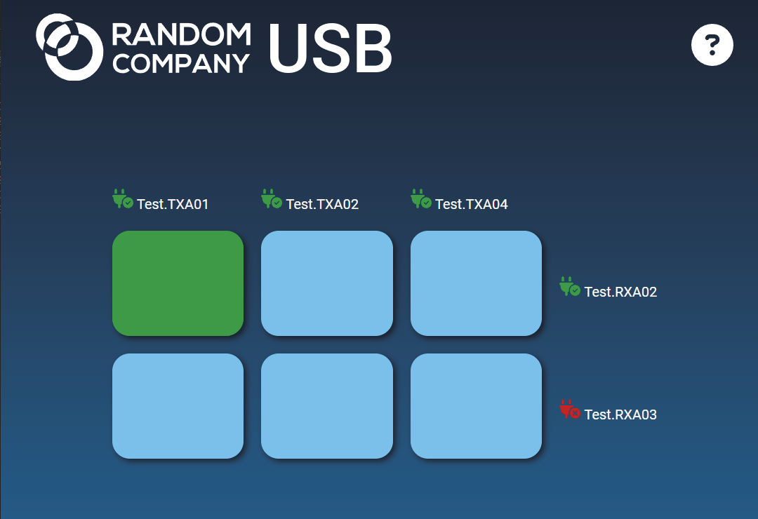
5.1.6. Blank Template
Blank template which contains an HTML frame but no graphical contents. The template can be freely customized in the Content panel, see more details about it in the Personalizing of the UI section.

5.2. Password Protection for Touchpanel
DIFFERENCE:The feature is available from LARA v2.0.0.
Description
API key and login password can be set for LARA Touchscreen UI Module to ensure only authorized users to be allowed accessing the touchpanel.
5.2.1. User Panel Instance
After selecting a user panel template, a custom user defined API key and password can be added between the instance parameters.
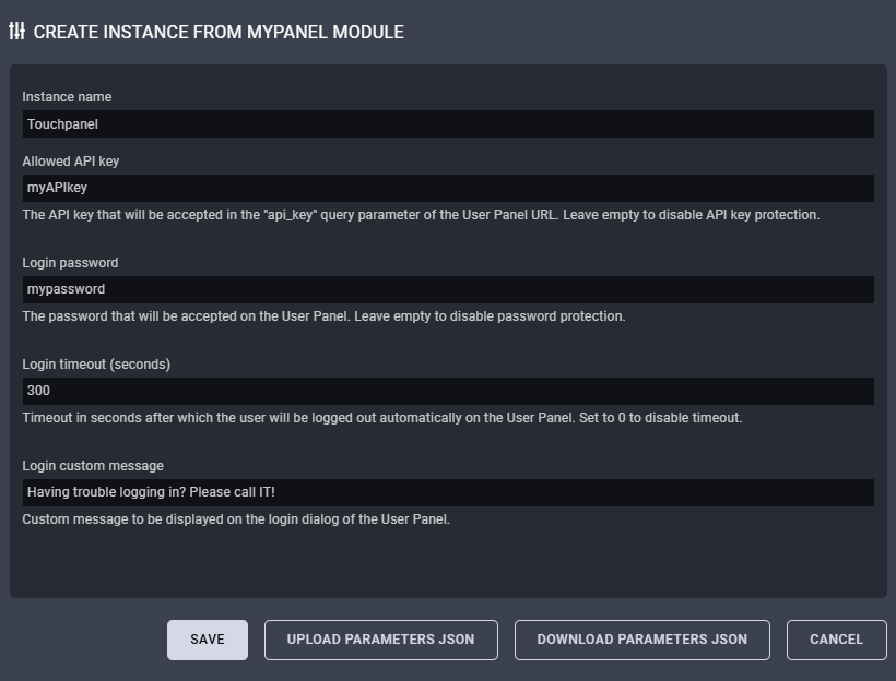
Instance parameters for touchscreen UI module
DEFINITION:API key: it is a unique, secret code that identifies and authenticates a device when it requests access to another software system's API (Application Programming Interface) to exchange data or functionality, acting like a simplified password to control and log API usage, set access limits, and prevent unauthorized access. It's a string of alphanumeric characters that authorizes specific actions and tracks activity for security and management.
5.2.2. Parameters and Explanations
Allowed API key
The API key that will be accepted in the "api_key" query parameter of the User Panel URL.
INFO:If the field is left empty, API key protection will be disabled.
When API key is applied, the user panel URL gets an api_key tag which grants just that users can open the link who knows the custom API key.
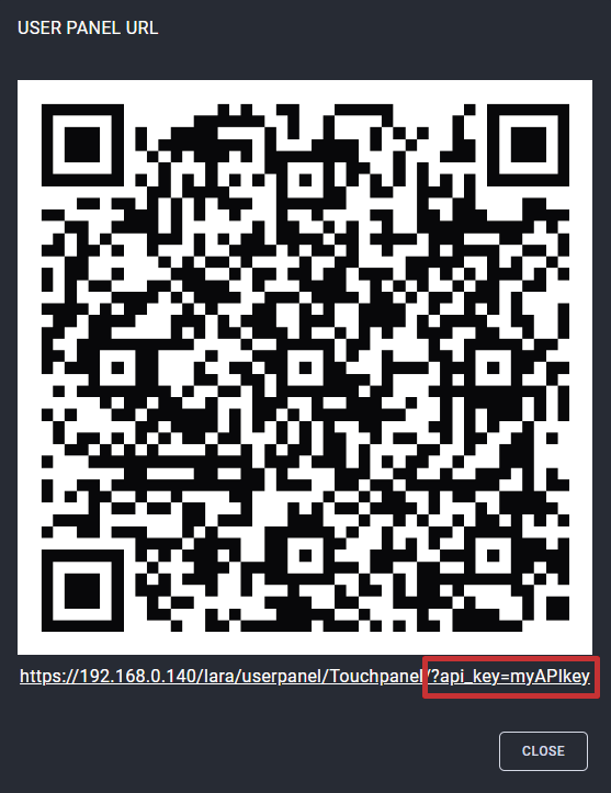
User panel URL with the highlighted API key
Login Password
The password that will be accepted on the User Panel.
INFO:If the field is left empty, password protection will be disabled.
When login password is applied, a login screen pops up after opening the user panel URL.
![[Alt text was not generated.]](UM-web-resources/image/TchS_Psw_03.png)
Login screen on the LARA touchpanel
Login Timeout
Timeout in seconds after which the user will be logged out automatically on the User Panel.
INFO:If the field value is 0, login timeout will be disabled.
Login Custom Message
Custom message to be displayed on the login dialog of the User Panel. The field is optional.
![[Alt text was not generated.]](UM-web-resources/image/TchS_Psw_05.png)
Login dialog with the highlighted custom message
5.2.3. Customization of the Login Dialog
The login dialog can be customized in the Content panel by the user. Edit the user panel Module by clicking on the icon. Go to the Content section and select the login.html. See more details about the personalization in the Personalizing of the UI section.
![[Alt text was not generated.]](UM-web-resources/image/TchS_Psw_06.png)
Editing in the User panel content libraries
5.3. Dashboard and Personalization
5.3.1. Dashboard Content
The following status indicator is displayed on the Status board:
▪QR code and link to the Touchscreen UI
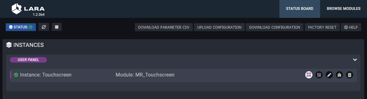
Clicking on the icon pops up the scannable QR code and the link of the touchscreen UI.
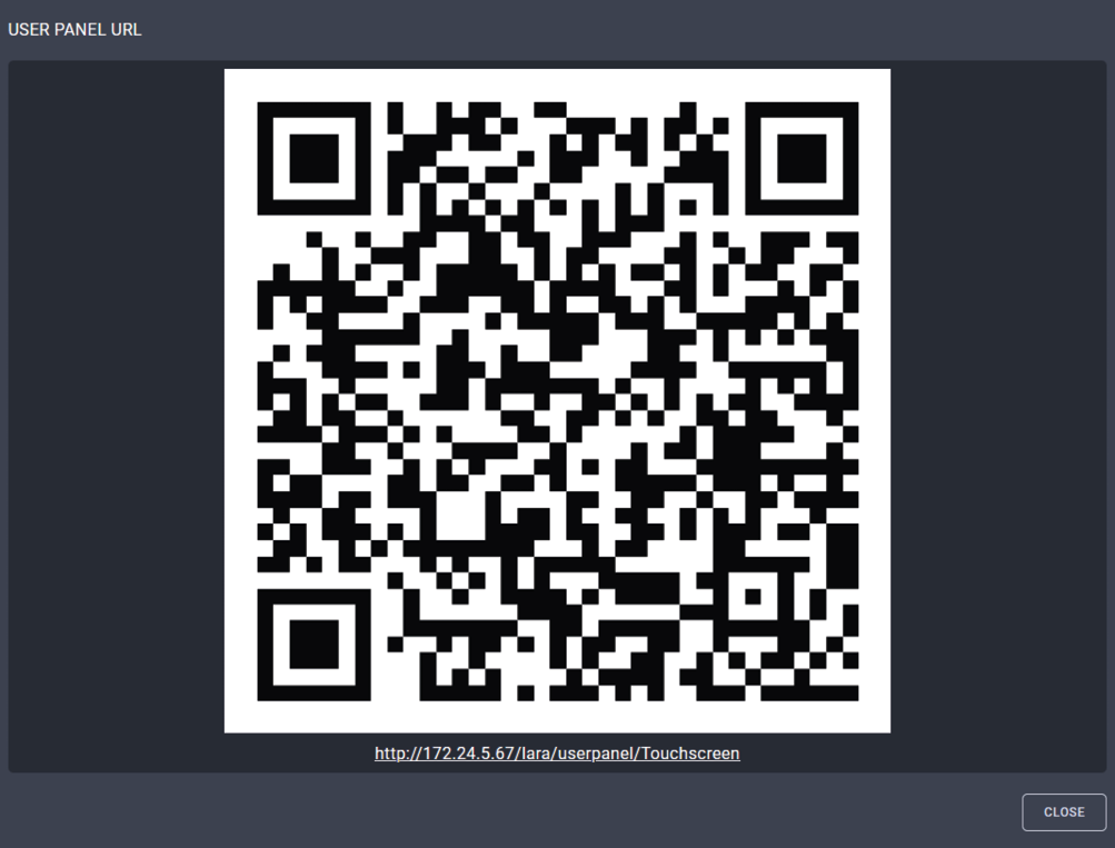
5.3.2. Editing of the Module
Click on the icon to edit the Parameters of the Module and to get more information about it.
The following sections are available in the user panel Module:
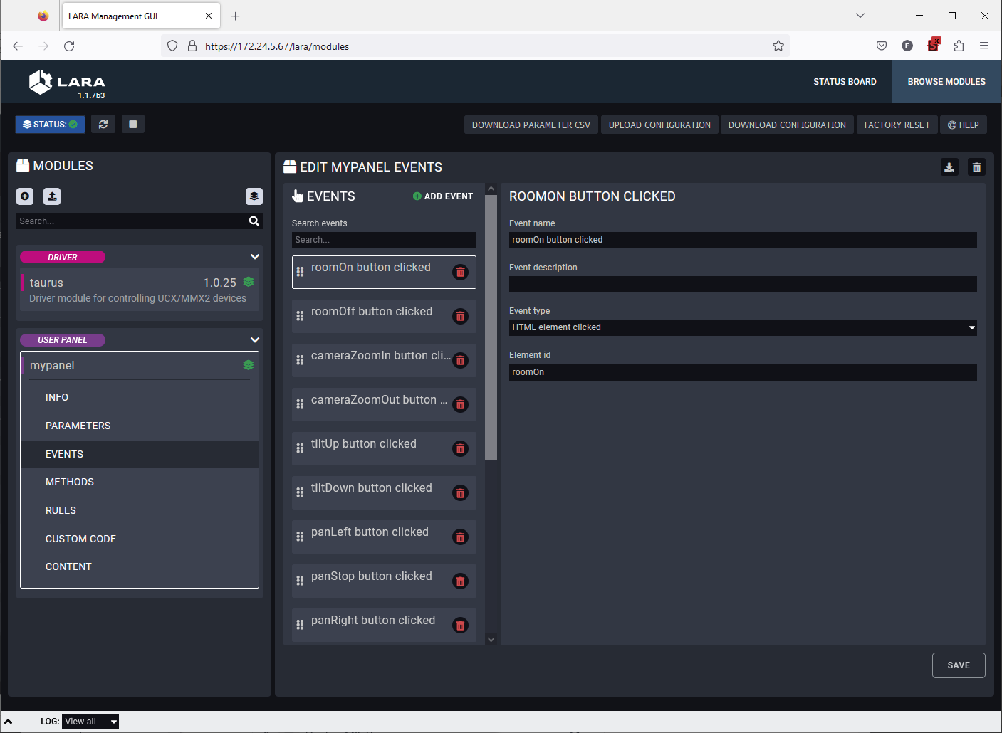
▪Info: it can be filled with basic user information about the user panel like author, version, etc.
▪Parameters: Parameters can be added to the Module which can be used for the user panel. User defined Parameters can be used in Javascript code only.
▪Events: predefined Events can be cusomized or new Events can be added to the user panel interActions and a specific change (user interAction or Parameter change) that can be used as a Trigger.
▪Methods: Methods can be added to Module and Actions to run when an Event is triggered.
▪Rules: predefined Rules can be cusomized or new Rules can be added to the user panel interActions. In case of User Modules, the Rule can be arranged in the Module, Logic Module is not necessary.
▪Custom code: custom user code in javascript can be uploaded.
▪Content: the original HTML and CSS code of the chosen template can be reviewed and customized here.
5.3.3. Personalizing of the UI
This section shows how to personalize the touchscreen UI templates through some simple examples. The Huddle Room Light template will be used in the following samples.
Changing of the Company Logo
The template contains a logo which is displayed on the touchscreen UI by default. The logo can be changed easily in few simple steps.
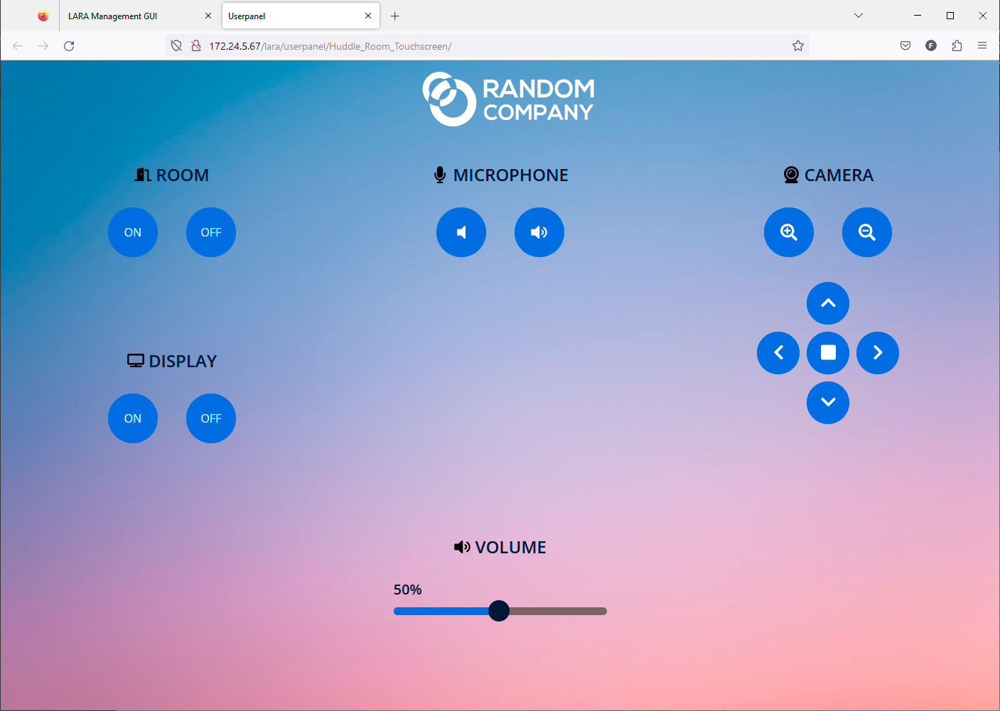
Huddle Room Light template with the default company logo
Uploading the New Logo
Step 1.Edit the user panel Module by clicking on the icon. Go to the Content section and select the img folder.
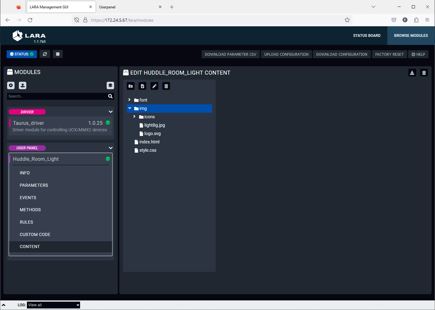
Editing in the User panel content libraries
TIPS AND TRICKS:The content or the files can be uploaded by drag&drop, too.
Step 2.Upload the new company logo to the img folder. Click on the Upload file icon. Browse the new logo file and upload it. Recommended file extension is .svg. In our example it is the LightwareLogo.svg.
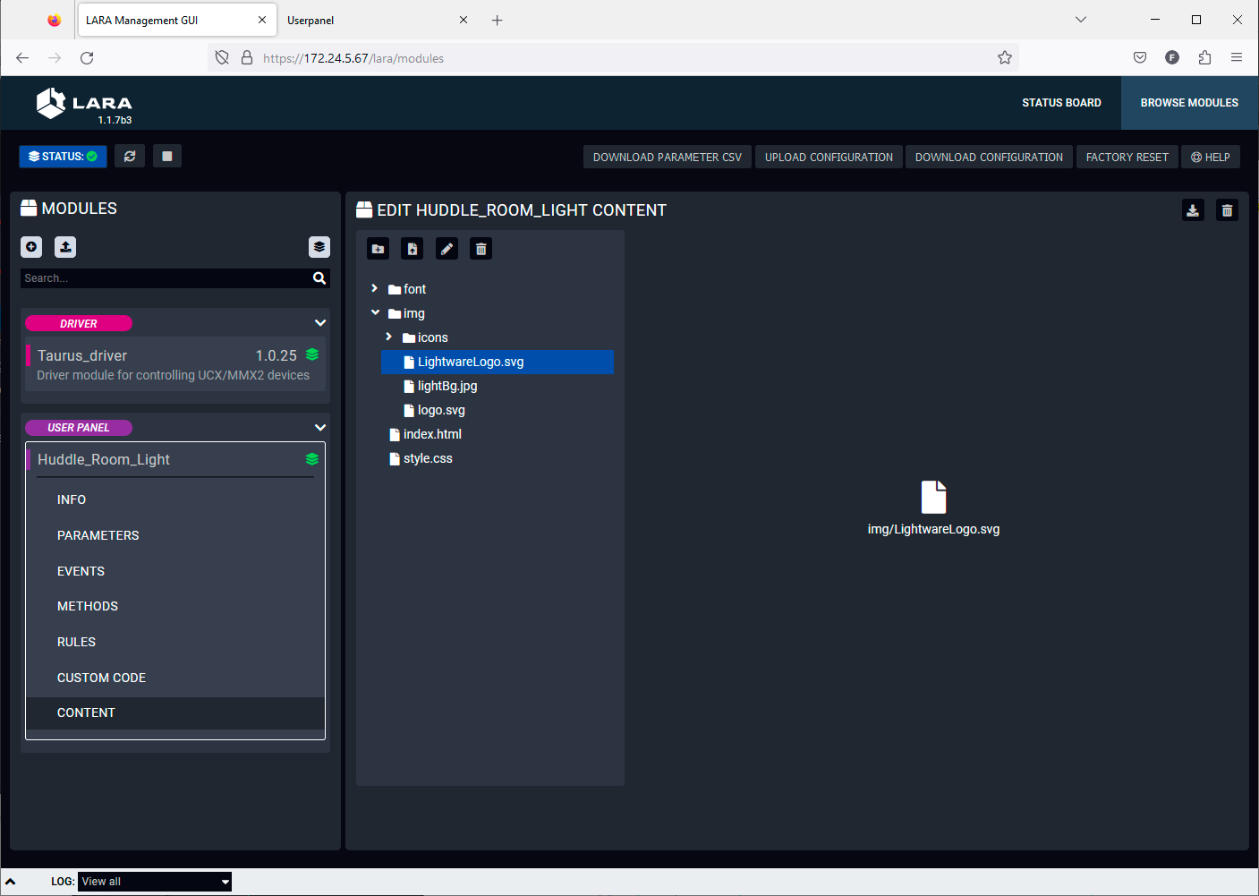
Uploading a new file
Editing of the CSS File
Step 3.Select the style.css and find the row in the code where the logo.svg is actually linked. In our example it is in the row 89. Edit the link of the logo file to the new one like in our example:
|
Original code: |
background: url(./img/logo.svg) no-repeat center left; |
|
Edited code: |
background: url(./img/LightwareLogo.svg) no-repeat center left; |
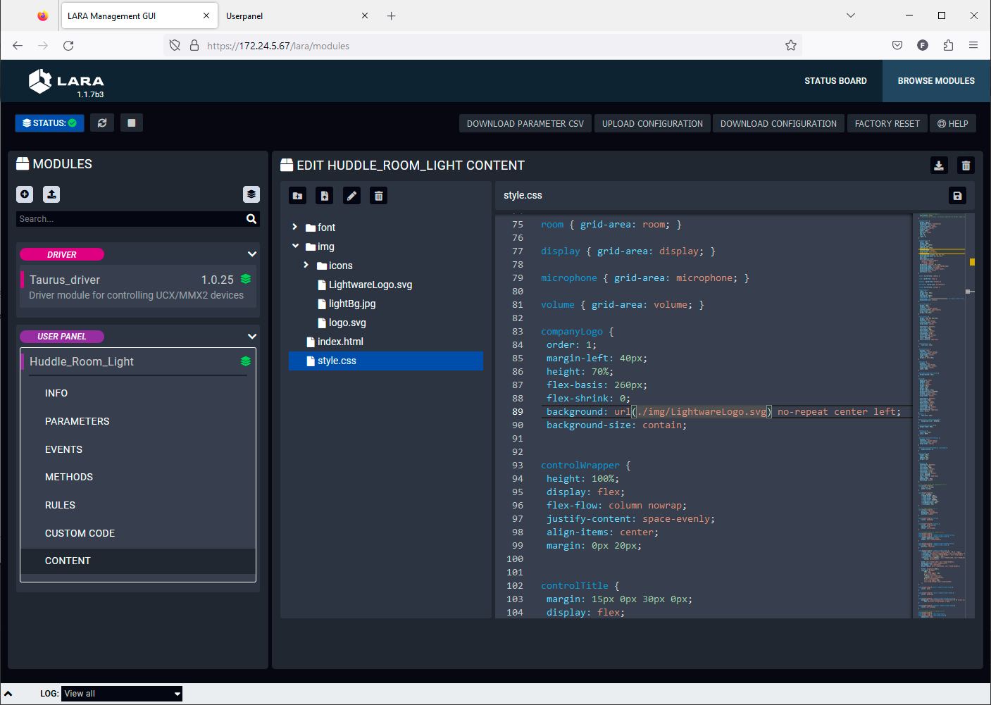
Editing of the CSS file
Step 4.Save the style.css by clicking on the Save file icon.
Refreshing of the Touchscreen UI
Step 5.Go the touchscreen panel UI and refresh it in the web browser. The new company logo appears immediately.
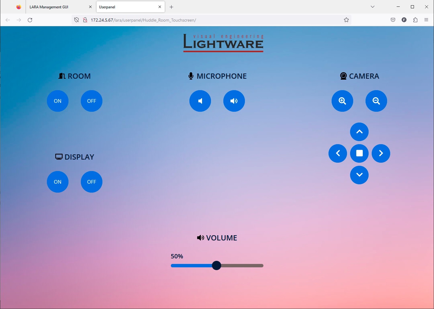
Touchscreen UI with the new company logo
Changing the Color of the Buttons
The next few steps show how to change the color of the buttons.
Editing of the CSS File
Step 1.Select the style.css and find the row in the code where the background color of the buttons are defined. In our example it is in the row 155.
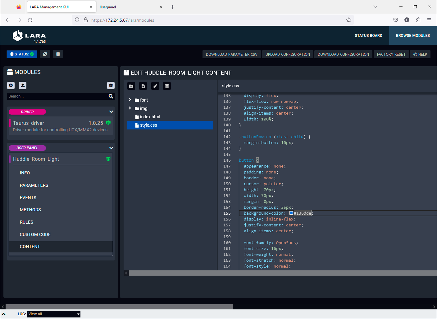
Editing of the CSS file
Step 2.Type the wished RGB code after the # character or select it in the color picker pop-up window.
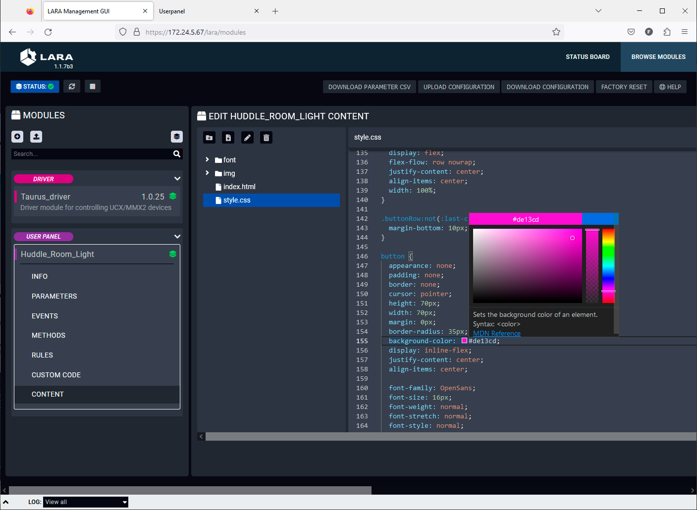
Color picker pop-up window in the CSS editor
Step 3.Save the style.css by clicking on the Save file icon.
Step 4.Go the touchscreen panel UI and refresh it in the web browser. The new button color appears immediately.
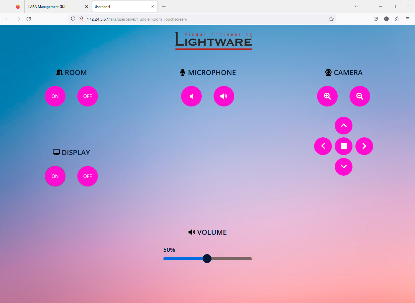
The user panel with the new button colors
Adding Feedback Indicators to the Buttons
A feedback from the UI that makes it visible that the interaction actually happened is a valid user requirement. The following section shows how to do it in the touchscreen panel Module.
Example Description
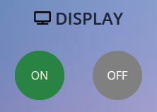
The Display On button shall change its color to green when it is clicked and parallel, the Display Off button shall change its color to grey.
When Display Off button is clicked, its color shall change to green and parallel, the Display On button shall change its color to grey.
Adding Rule Action Steps
Step 1.Edit the user panel Module by clicking on the icon. Navigate to the Rules section and select the Handle displayOn button clicked Rule.
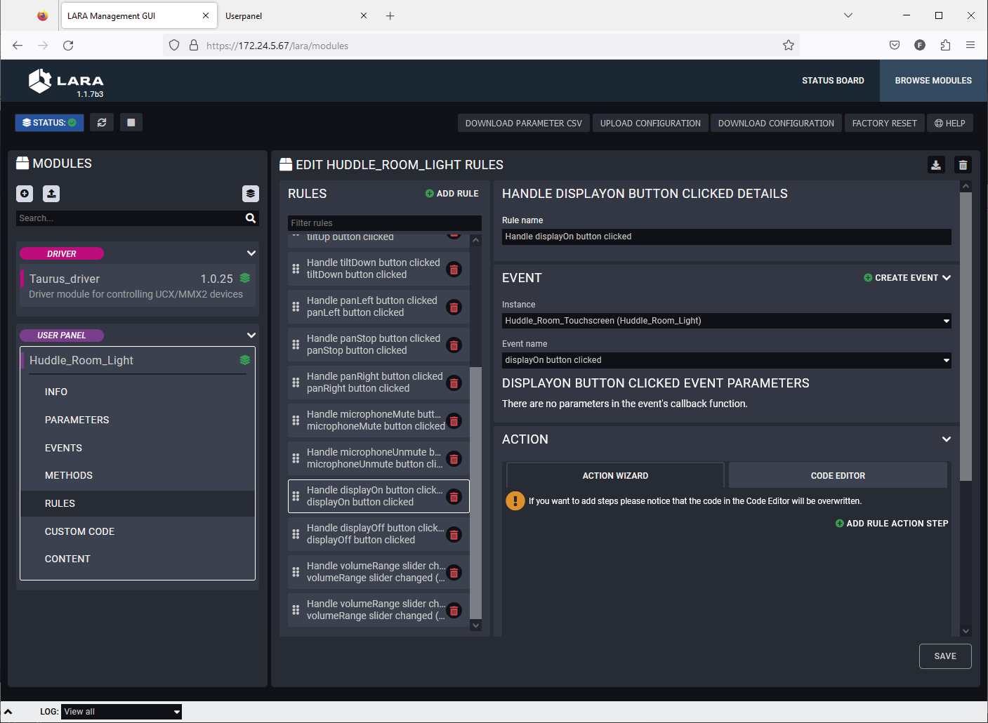
User panel - Rule editor
Step 2.Click on the Add Rule Action step button. Fill the fields with the following values. Click on the Save button when it is done.
|
Name |
DisplayOn color green |
|
Description |
Color of the Display On button changes to green when it is clicked. |
|
Select Action step |
Set HTML Element CSS Style |
|
HTML Element ID |
displayOn |
|
CSS Property name |
background-color |
|
CSS Property value |
green |
Step 3.Click on the Add Rule Action step button again. Fill the fields with the following values. Click on the Save button when it is done.
|
Name |
DisplayOff color grey |
|
Description |
Color of the Display Off button changes to grey when Display On is active. |
|
Select Action step |
Set HTML Element CSS Style |
|
HTML Element ID |
displayOff |
|
CSS Property name |
background-color |
|
CSS Property value |
grey |
Step 4.Navigate to the Rules section and select the Handle displayOff button clicked Rule.
Step 5.Click on the Add Rule Action step button. Fill the fields with the following values. Click on the Save button when it is done.
|
Name |
DisplayOff color green |
|
Description |
Color of the Display Off button changes to green when it is clicked. |
|
Select Action step |
Set HTML Element CSS Style |
|
HTML Element ID |
displayOff |
|
CSS Property name |
background-color |
|
CSS Property value |
green |
Step 6.Click on the Add Rule Action step button again. Fill the fields with the following values. Click on the Save button when it is done.
|
Name |
DisplayOn color grey |
|
Description |
Color of the Display On button changes to grey when Display Off is active. |
|
Select Action step |
Set HTML Element CSS Style |
|
HTML Element ID |
displayOn |
|
CSS Property name |
background-color |
|
CSS Property value |
grey |
Step 7.Click on the Save button to apply the recent changes. Accept to Restart LARA service.
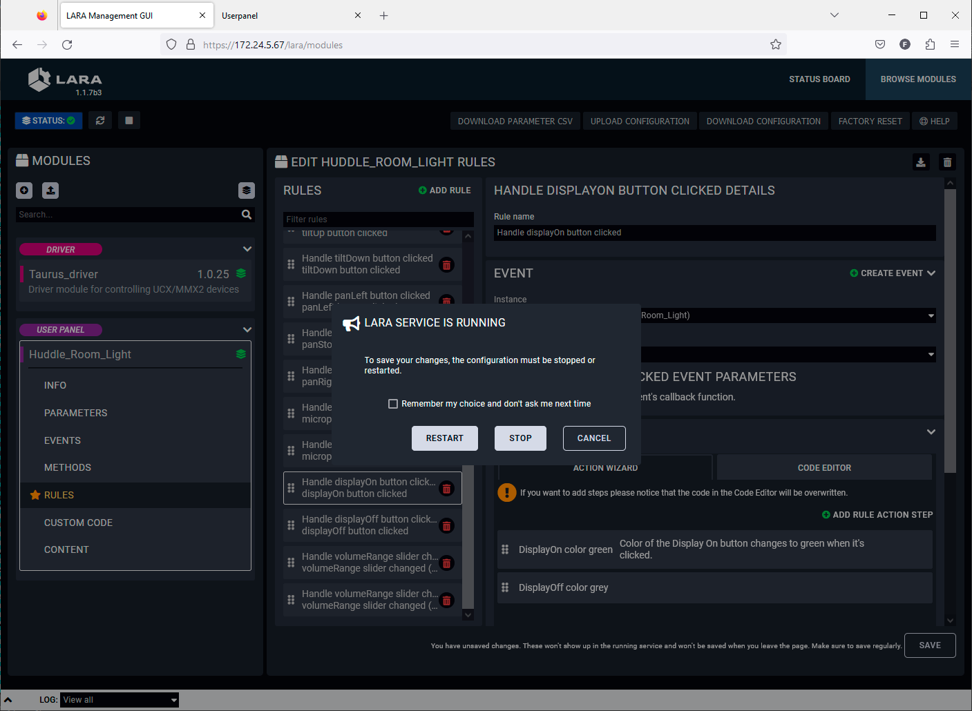
LARA service warning window
Step 8.Go the touchscreen panel UI. After restarting the LARA service the UI will be refreshed automatically and the new button style appears.
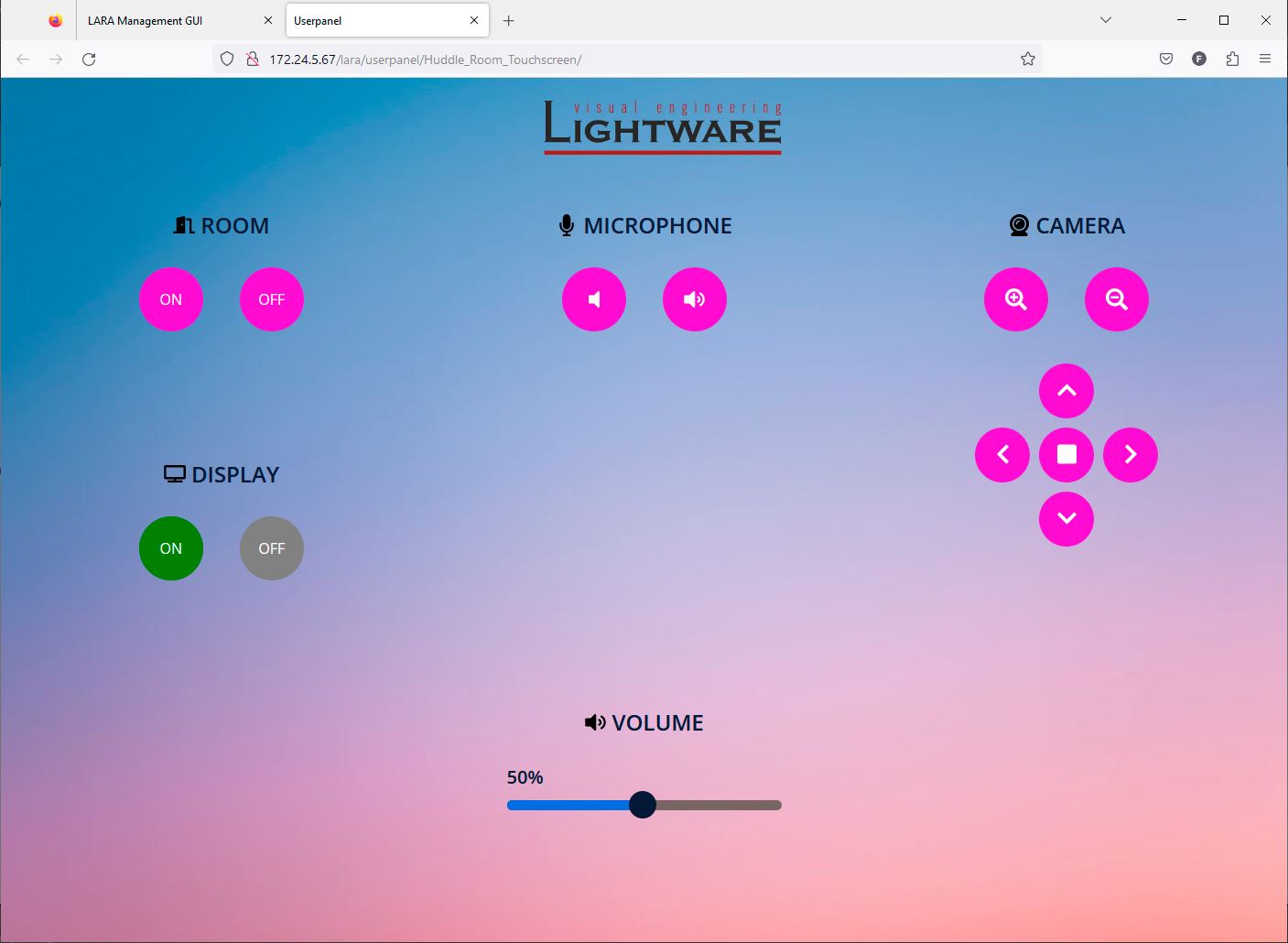
The user panel with the new button style
TIPS AND TRICKS:The example above is one possibility to customize the image of the touchscreen panel. Every element that has CSS property can be re-colored / resized / added new element (for example border around the buttons) etc. Only your imagination can set the limit.
This chapter is about building up a whole configuration. The example starts from scratch as LARA contains no configuration.
6.1. Basic LED Toggle
What Will Happen?
A simple button (dry contact) is connected to GPIO PIN1 and an LED to PIN4 of the UCX Taurus device. When the button is pressed, the LED is toggled to be switched on or off.
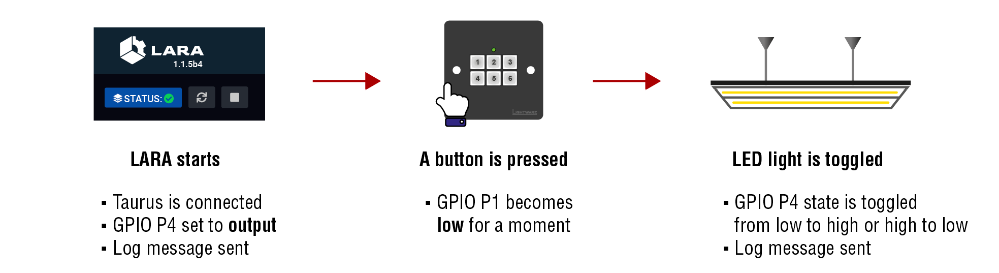
TIPS AND TRICKS:If you do not have devices to connect to the GPIO, you can Trigger and monitor the state changes in LDC:
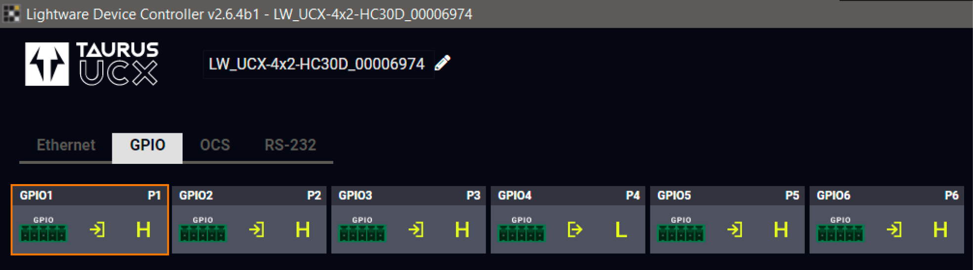
Configuration Steps
Step 1.Check the GPIO pin directions in LDC or web LDC and set the desired option.
Step 1.Creating the Driver Module(s).
Step 2.Creating the Logic Module.
Step 3.Creating Instances from the Modules.
Step 4.Creating Events in the Drived Module(s).
Step 5.Creating Rules in the Modules.
Step 6.Starting the configuration.
Step 1. Creating the Driver Module: taurus-ucx-mmx2-Driver
Add new Module
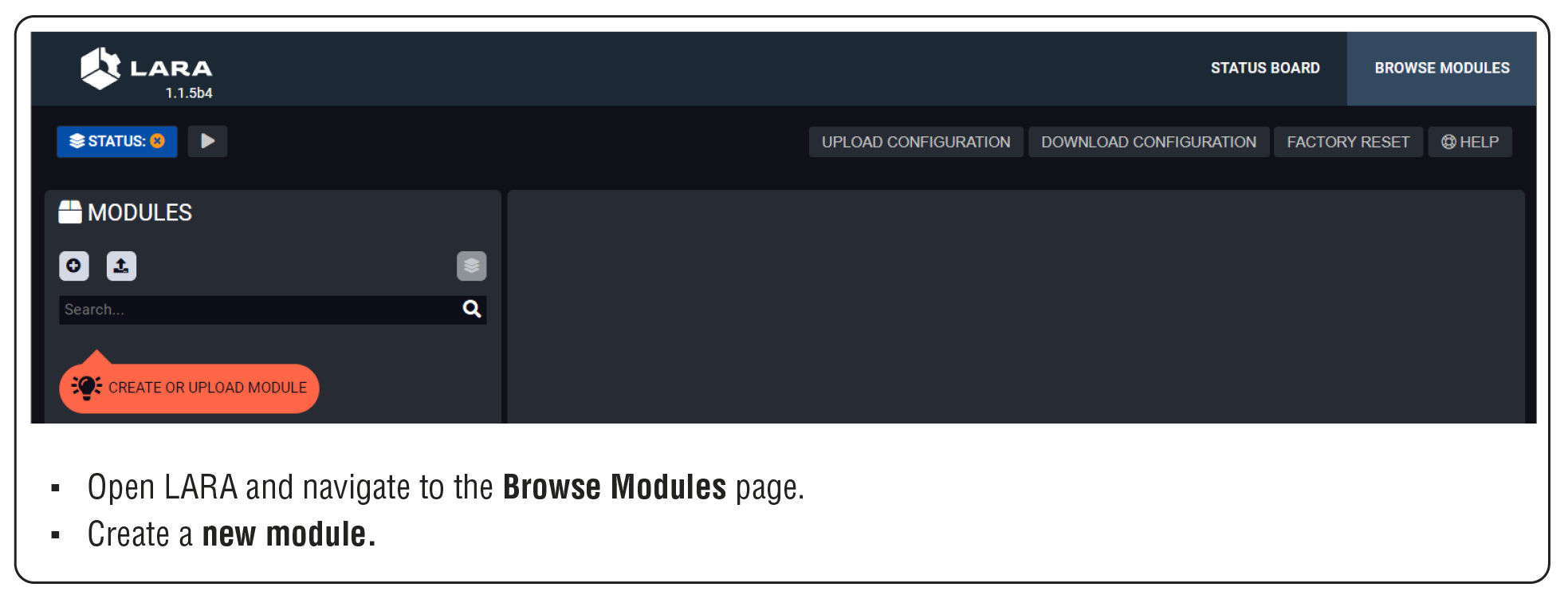
Create Taurus Driver
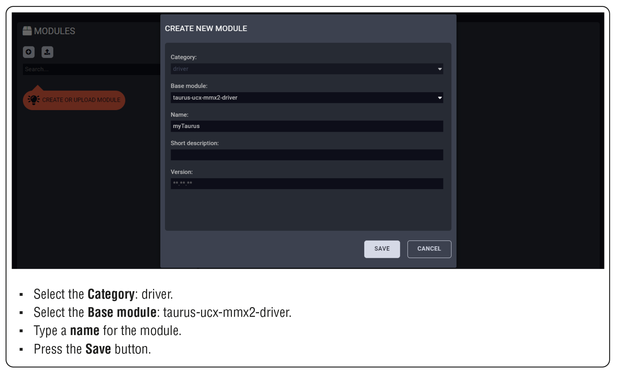
Step 2. Creating the Logic Module: Logic
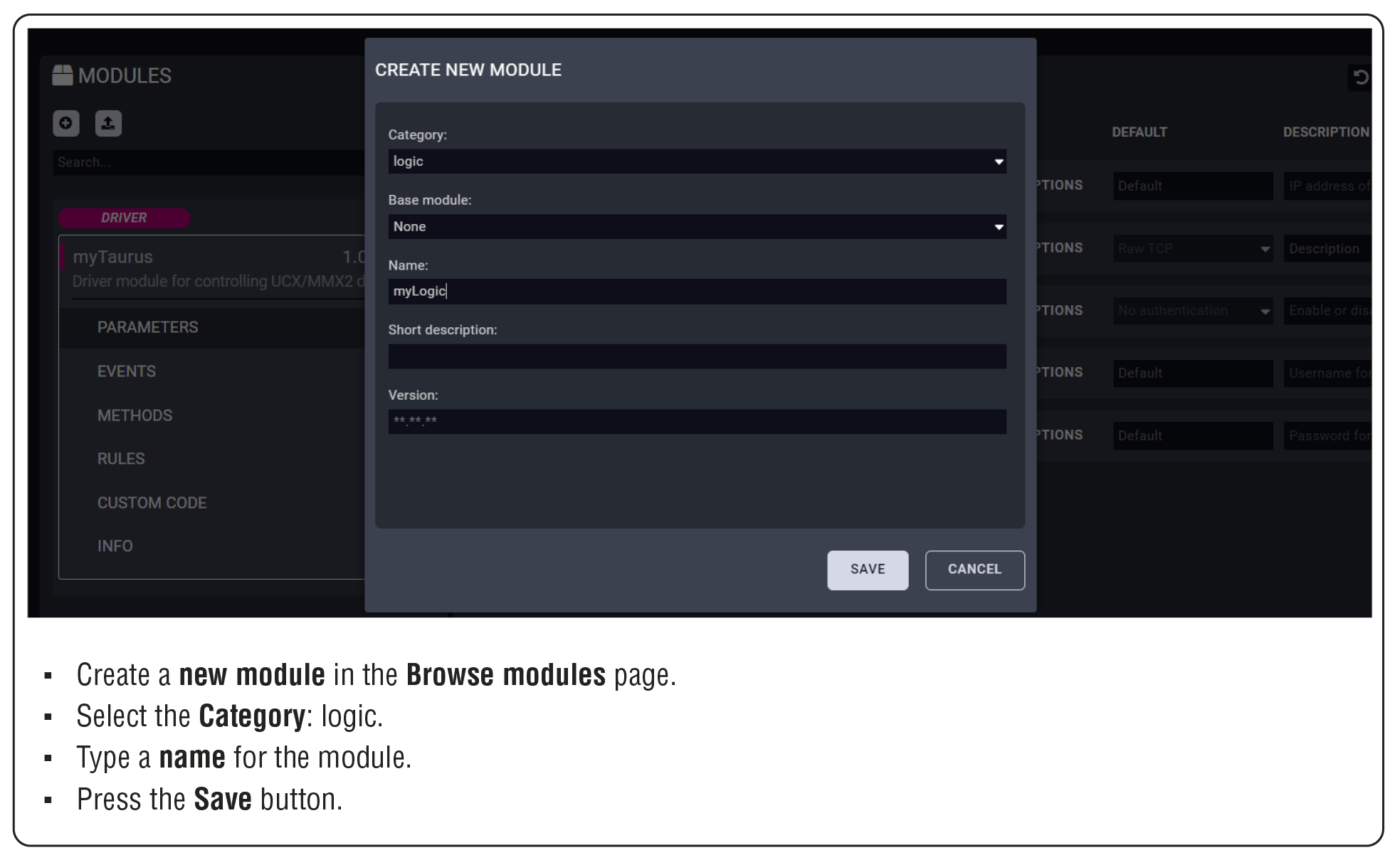
Step 3. Creating the Instances from the Modules
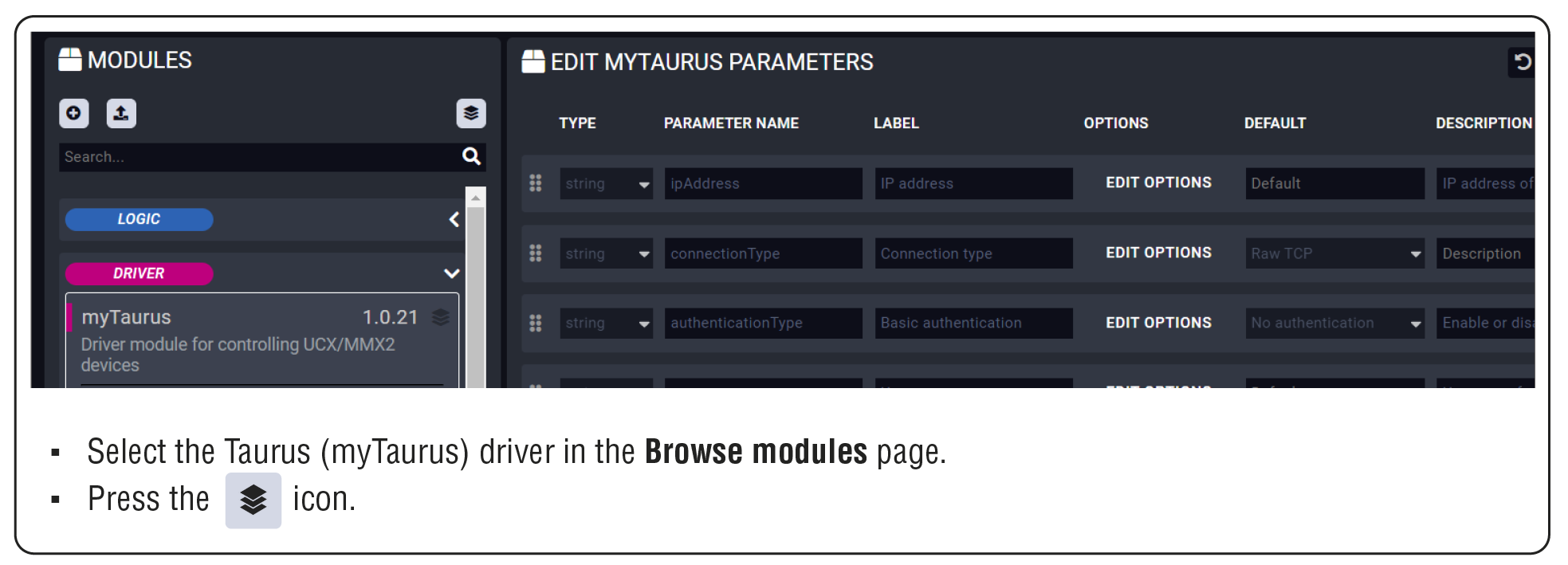
Saving the MyTaurus_inst Instance
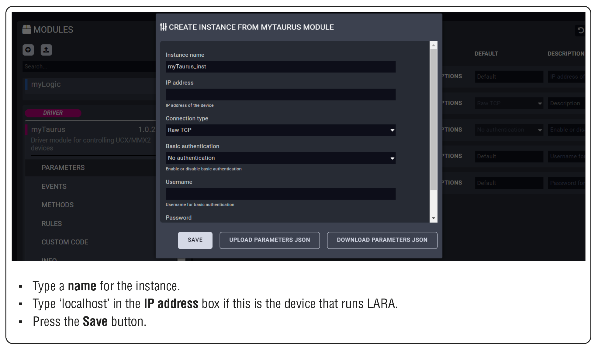
Saving the myLogic_inst Instance
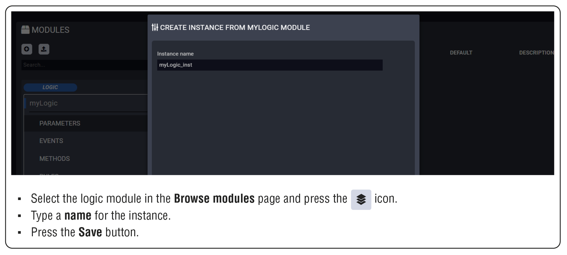
Step 4. Creating Event(s) in the Driver Module
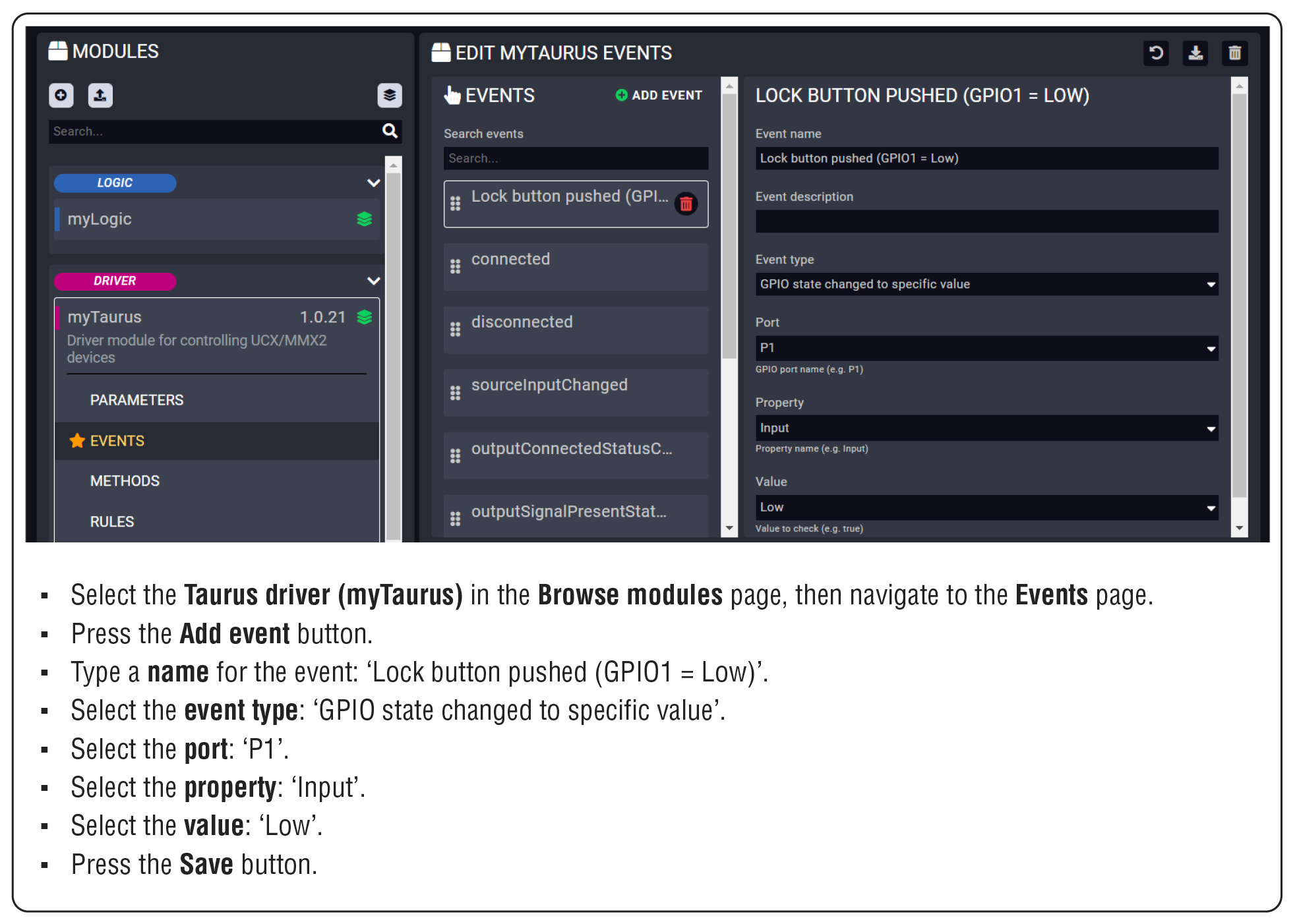
Step 5. Creating Rules in the Modules
Initializing the GPIO pin in the Taurus when LARA starts – Taurus Module
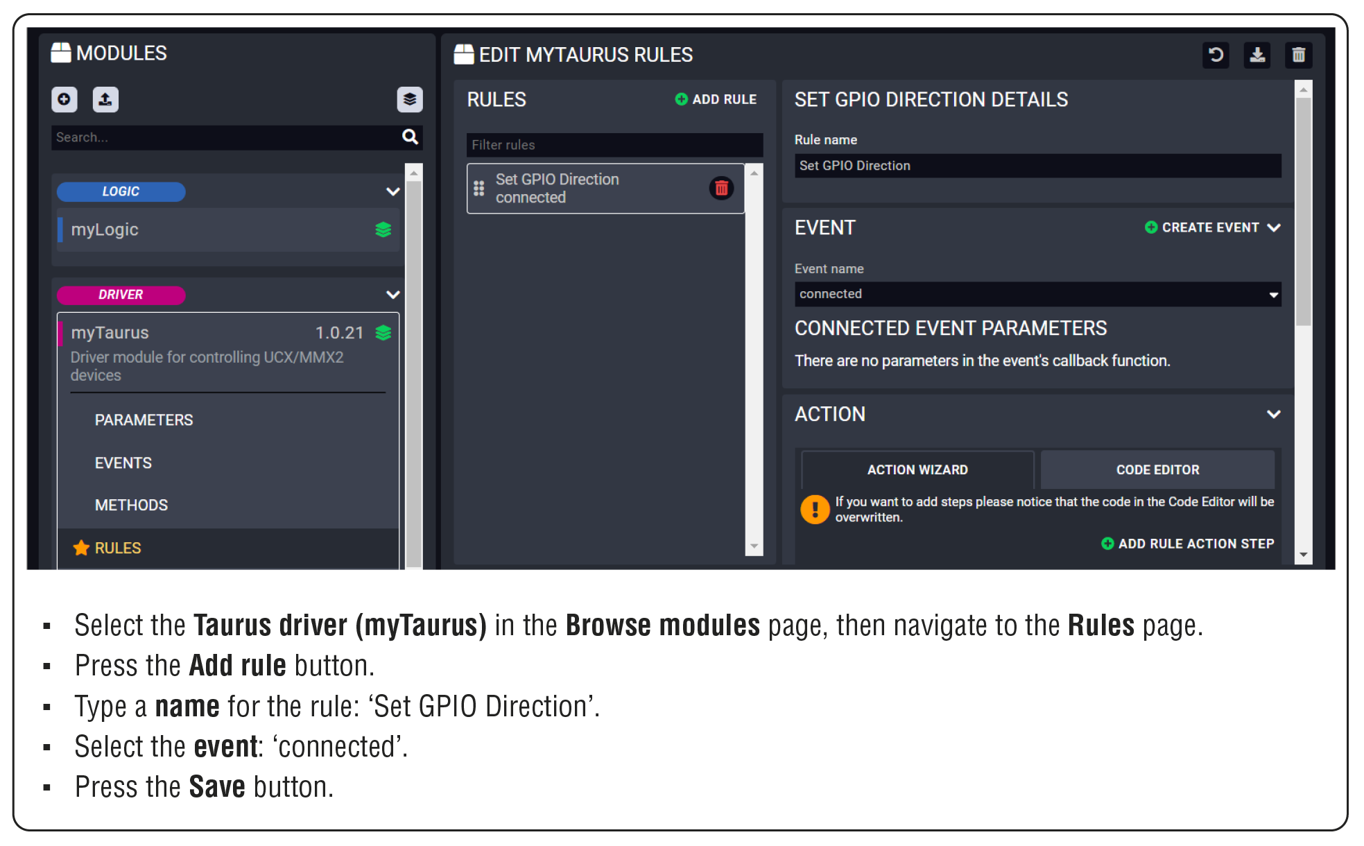
Adding the first Action step: logging a short message
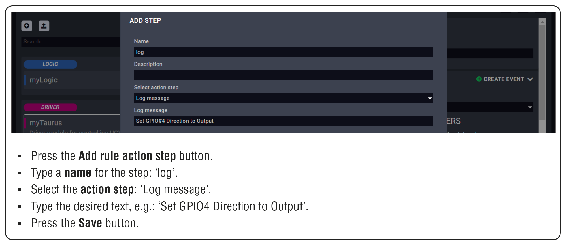
Adding the second Action step: setting the GPIO pin direction
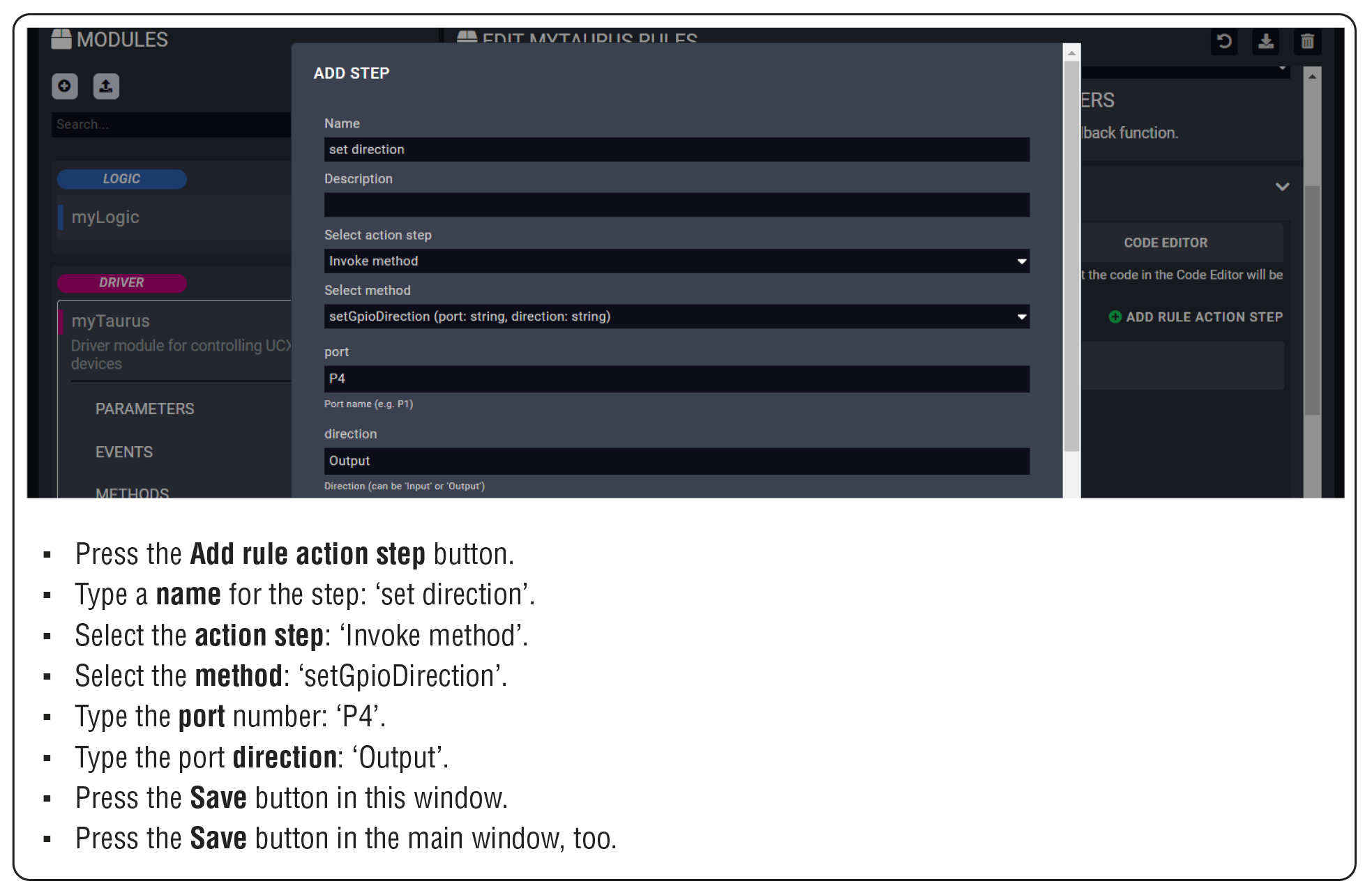
After that, the Action steps look like this:
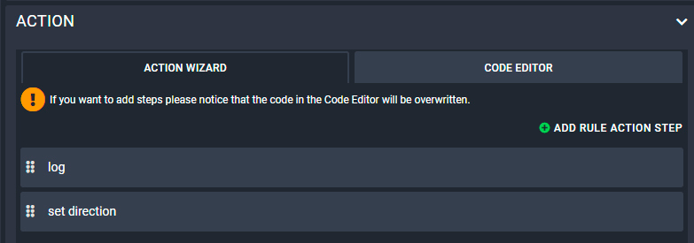
Toggle the output level of P4 – Logic Module
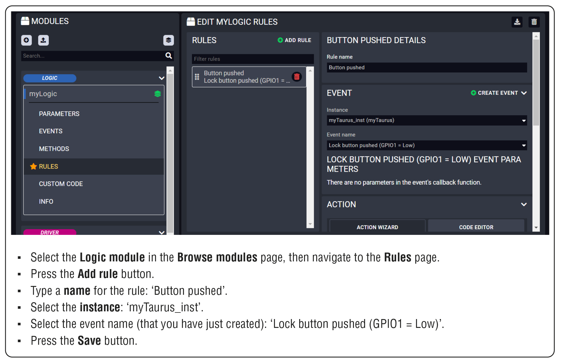
Adding the first Action step: logging a short message
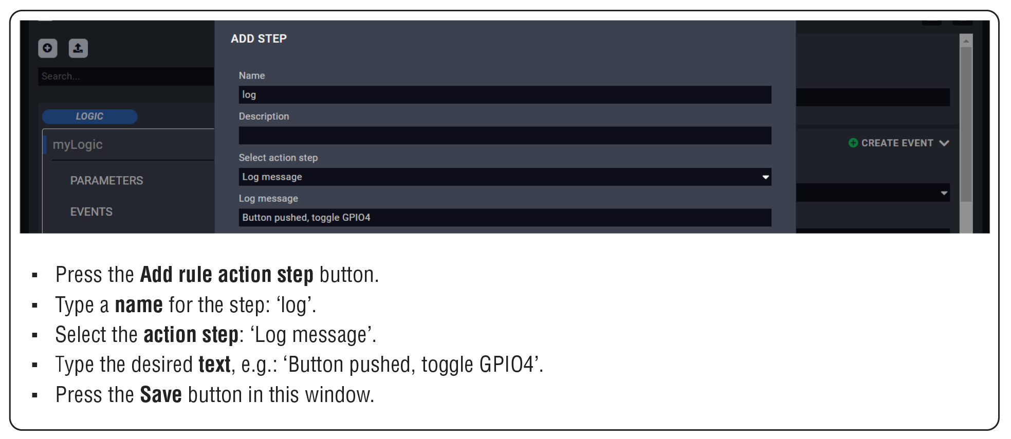
Adding the second Action step: toggle the GPIO pin output level
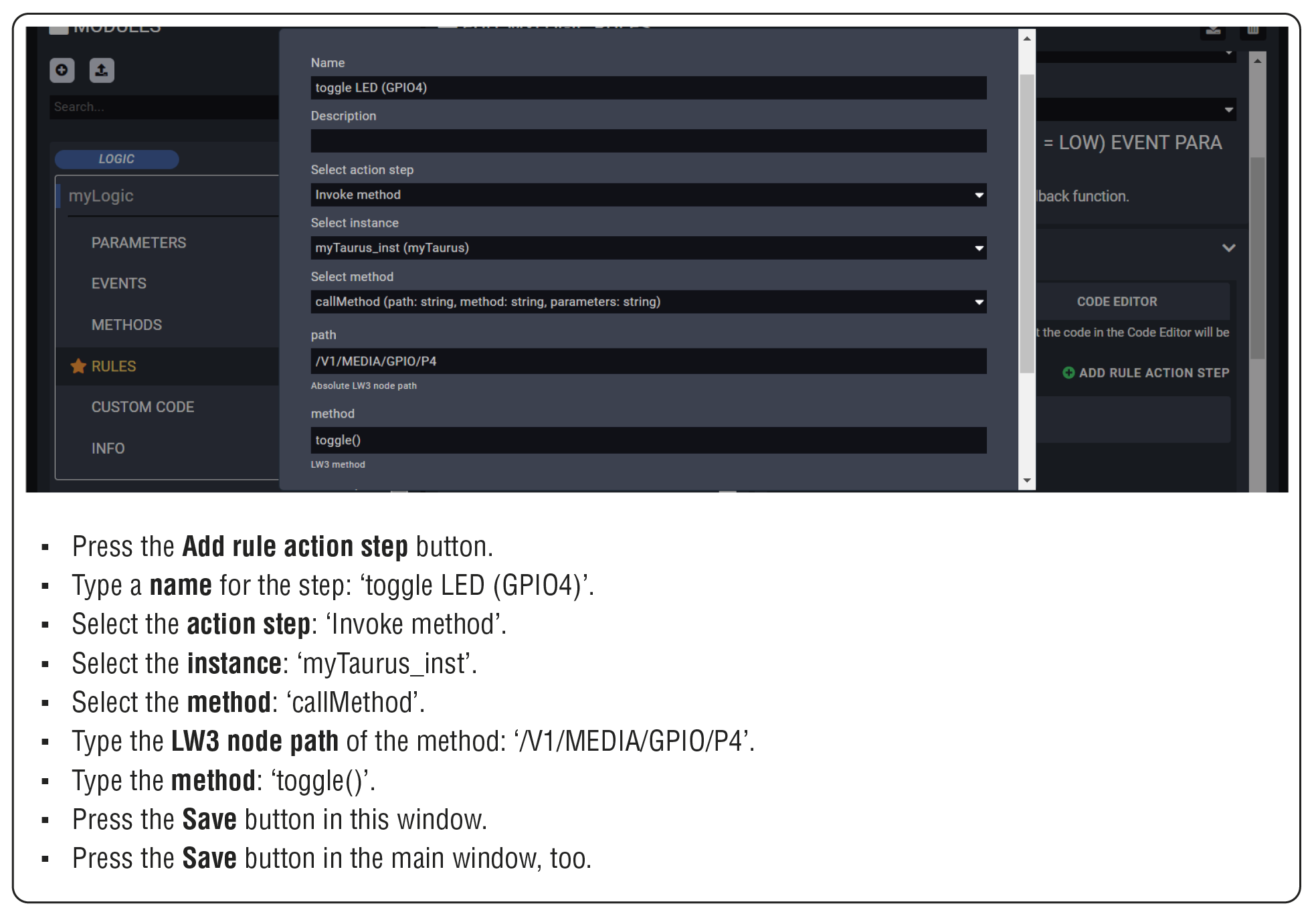
Step 6. Starting the configuration
The Configuration is ready to use, run LARA!

TIPS AND TRICKS:This configuration can be downloaded from Lightware's Cloud storage, so you can compare your work with the solution.
6.2. Configuration Steps for SDVoE Matrix
Configuration Steps in a Nutshell
Step 1.Creating the Driver module.
Step 2.Creating an Instance from the driver module.
Step 3.Creating the Userpanel module.
Step 4.Creating an Instance from the userpanel module.
Step 5.Starting of the LARA services.
Step 6.Configuration of the UI.
6.2.1. Creating the Driver Module
At first, LARA needs a driver module to handle the SDVoE extenders.
Step 1.Select the Create New Configuration button.
Step 2.Click on the button to create a new module.
Step 3.Fill out the parameters of the new module as follows:
=Category: driver
=Base module: @lwr-lara-modules/sdvoe-driver
=Name: a custom name.
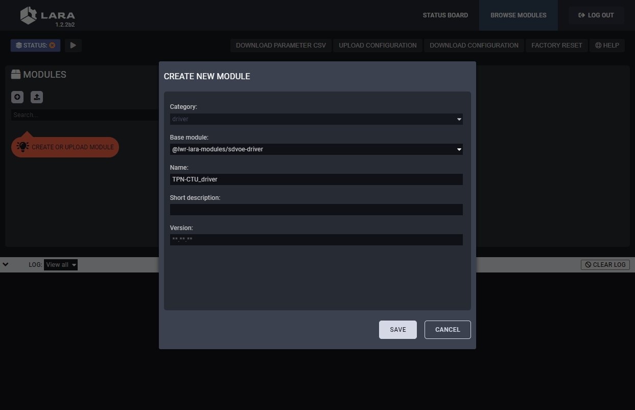
Step 4.Click on the Save button to complete the driver module.
6.2.2. Creating an Instance from the Driver Module
An instance is needed to be created from the driver module as follows:
Step 1.Click on the button to create an instance.
Step 2.Fill out the parameters of the new instance as follows:
=Instance name: a custom name (note down the given name, it must be used later)
=Connection type: WebSocket
=Host: the IP address of the TPN-CTU-X50
=Port: 8080
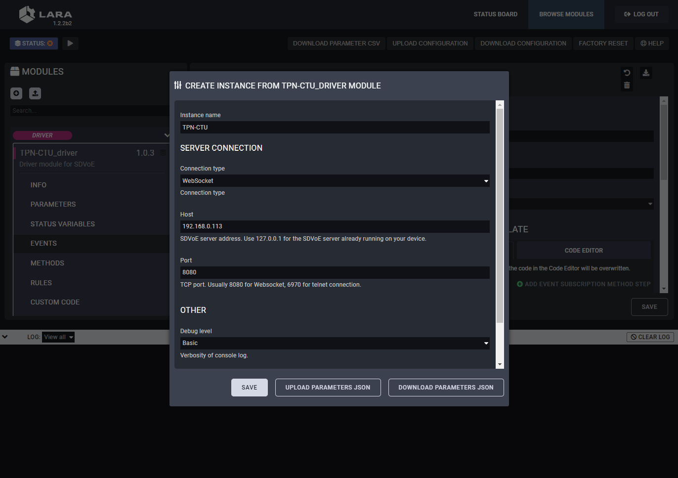
Step 3.Click on the Save button to complete the instance.
6.2.3. Creating the Userpanel Module
Users need a UI where the crosspoint settings can be managed.
Step 1.Navigate to the Browse Modules tab.
Step 2.Click on the button to create a new module.
Step 3.Fill out the parameters of the new module as follows:
=Category: userpanel
=Template: TPN small room
=Name: a custom name
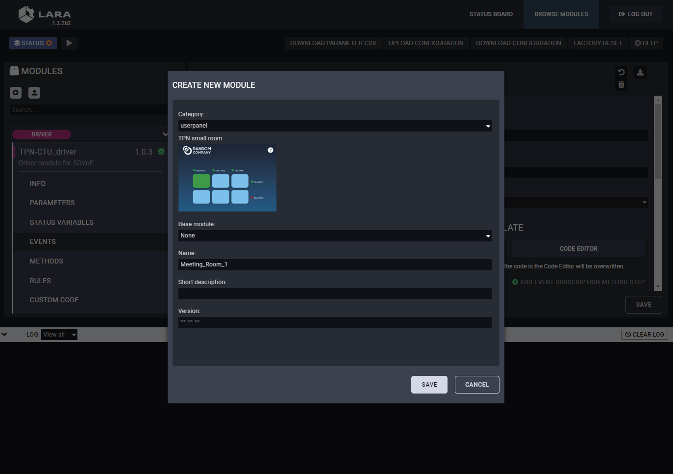
Step 4.Click on the Save button to complete the driver module.
TIPS AND TRICKS:The built-in templates can be customized freely and users can add new buttons and features to the touchpanel as well. See more personalization samples in the Personalizing of the UI section.
6.2.4. Creating an Instance from the Userpanel Module
An instance is needed to be created from the userpanel module as follows:
Step 1.Click on the button to create an instance.
Step 2.Fill out the parameters of the new instance as follows:
=Instance name: a custom name
=sdvoeInstanceId: the name of the instace created from the driver
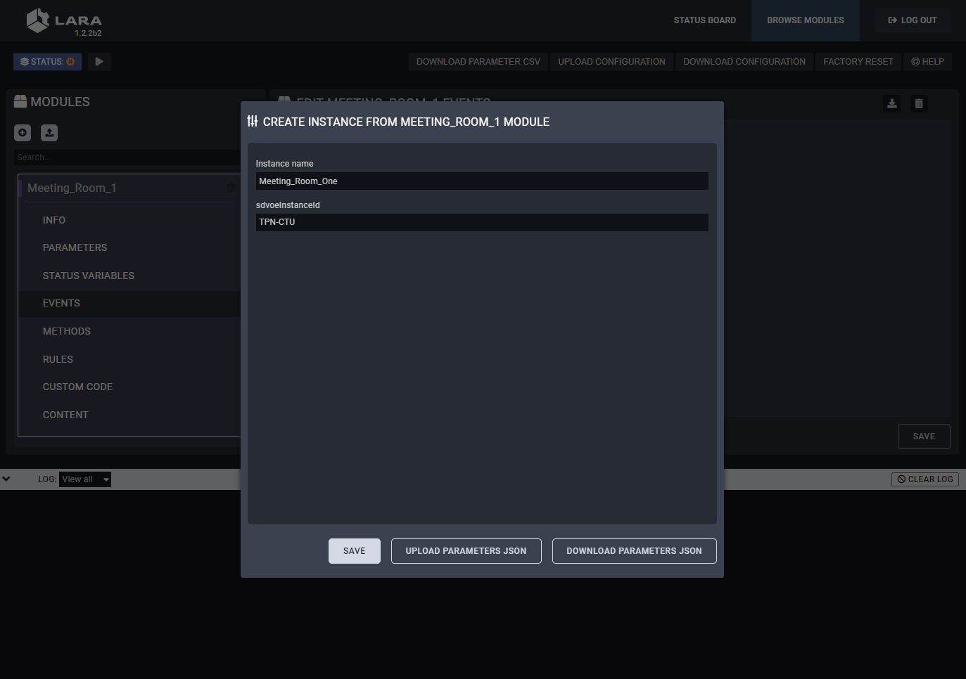
Step 3.Click on the Save button to complete the instance.
6.2.5. Starting of the LARA Services
LARA services need to be started by clicking on the button.
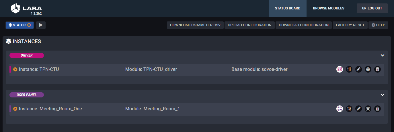
Services are not running in LARA
After the services start to run, the status board displays the details of the services.
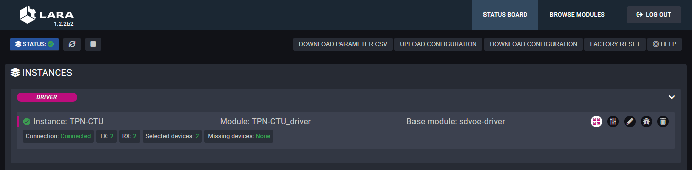
Services are running in LARA
The services can be stopped by clicking on the button and they can be restarted by clicking on the button.
Information on the Driver Status Board
|
Field |
Value |
Description |
|---|---|---|
|
Connection |
Connected |
TPN-CTU-X50 is online and managed by the LARA services. |
|
Disconnected |
TPN-CTU-X50 is not connected to the LARA services. |
|
|
TX |
<number> |
Number of the connected TPN/OPTN series transmitters. |
|
RX |
<number> |
Number of the connected TPN/OPTN series receivers. |
|
Selected devices |
<number> |
Number of selected TPN/OPTN series extenders in the Icron UI panel. |
|
Missing devices |
<number> |
Number of selected TPN/OPTN series extenders in the Icron UI panel that are disconnected from the network. |
6.2.6. Configuration of the UI
Accessing of the TPN GUI
Click on the icon in the status board of the TPN driver.
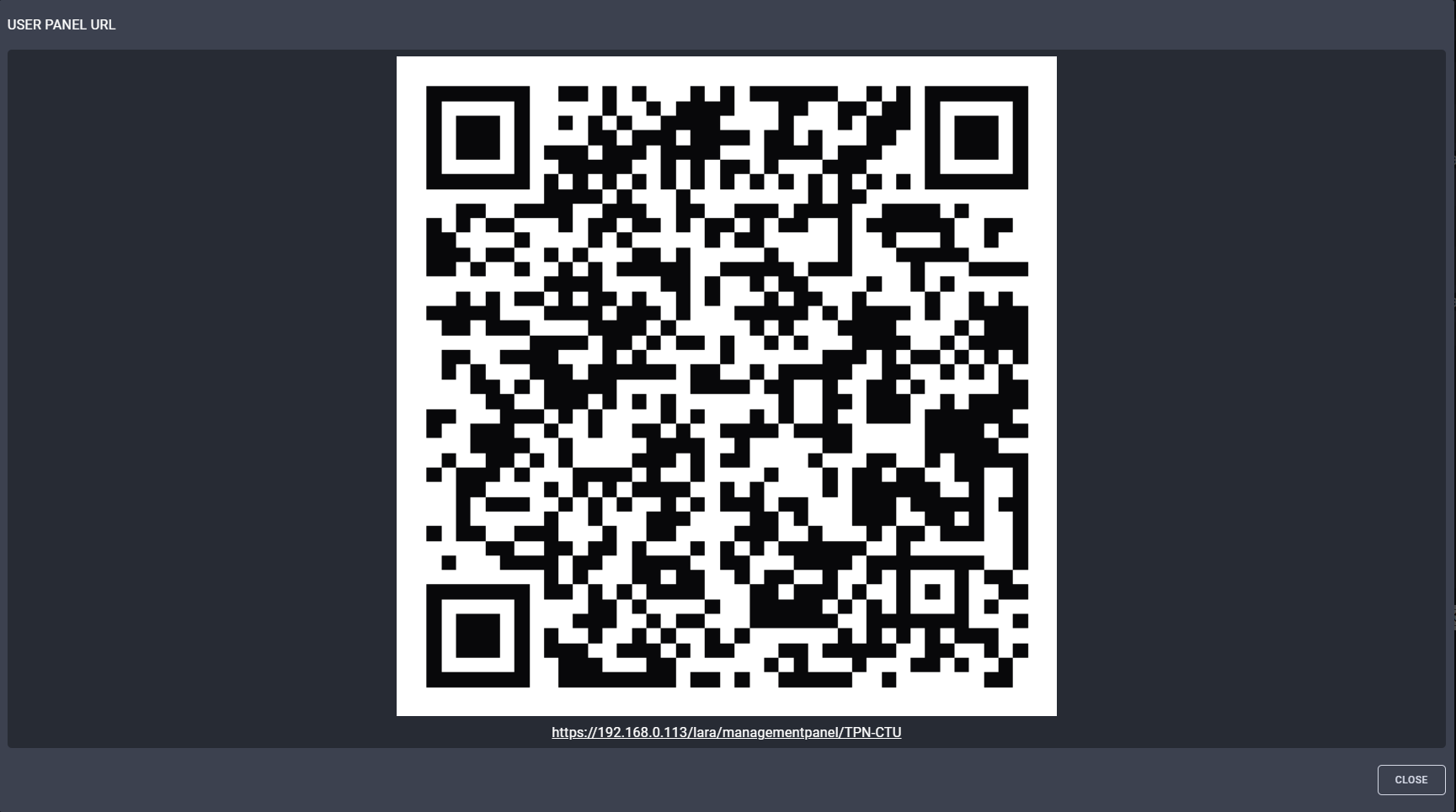
QR code and the direct link to the UI of the driver
Configuration of the Endpoint Devices with TPN GUI
Open the link that guides to the TPN GUI where the transmitters (Source) and the receivers (Sink) can be managed and the crosspoint table can be built.
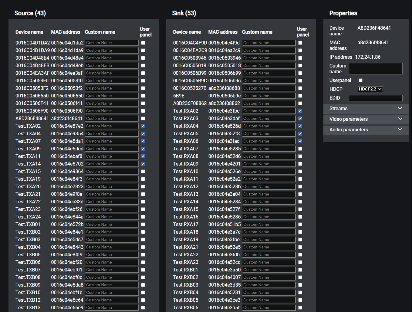
TPN GUI window
ATTENTION!The module can handle up to 20 endpoint devices, the screenshot above is an illustration only.
Description
The default device name of the endpoints is the ID of the device. It can be personalized in the Custom name field. Where the User panel checkbox is ticked in, the stream of the endpoint will appear on the Userpanel as a crosspoint possibility.
Select an endpoint device to check the parameters in the Properties section. The panel displays information about the transmitted audio/video stream and in case of scaling receivers (-SR models), the parameters of the scaler can be set.
Crosspoint View on the TPN Userpanel
Click on the icon in the status board of the SDVoE userpanel:
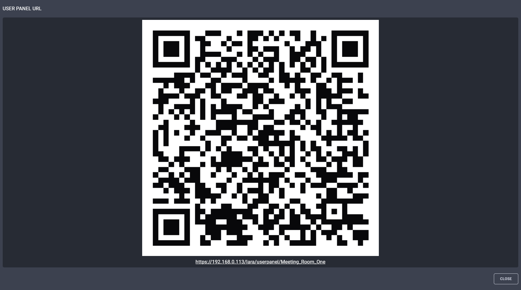
QR code and the direct link to the userpanel
Open the link that guides to the user panel where the crosspoint settings can be managed.
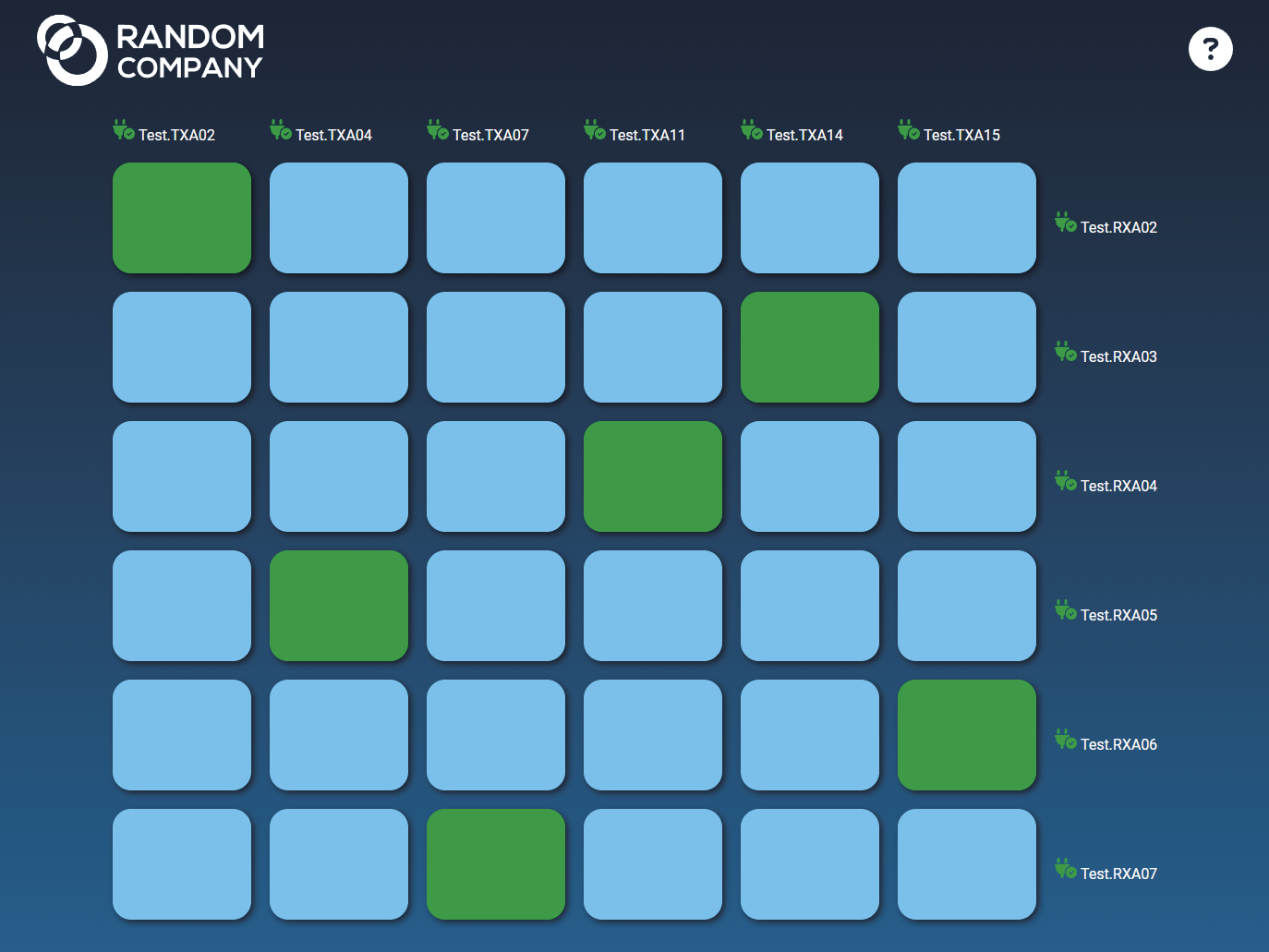
Crosspoint UI of a sample 6x6 TPN matrix system
6.3. Configuration Steps for Icron USB 2.0
Configuration Steps in a Nutshell
Step 1.Creating the Driver module.
Step 2.Creating an Instance from the driver module.
Step 3.Creating the Userpanel module.
Step 4.Creating an Instance from the userpanel module.
Step 5.Starting of the LARA services.
Step 6.Configuration of the UI.
6.3.1. Creating the Driver Module
At first, LARA needs a driver module to handle the SDVoE extenders.
Step 1.Select the Create New Configuration button.
Step 2.Click on the button to create a new module.
Step 3.Fill out the parameters of the new module as follows:
=Category: driver
=Base module: @lwr-lara-modules/icron-usb20-driver
=Name: a custom name.
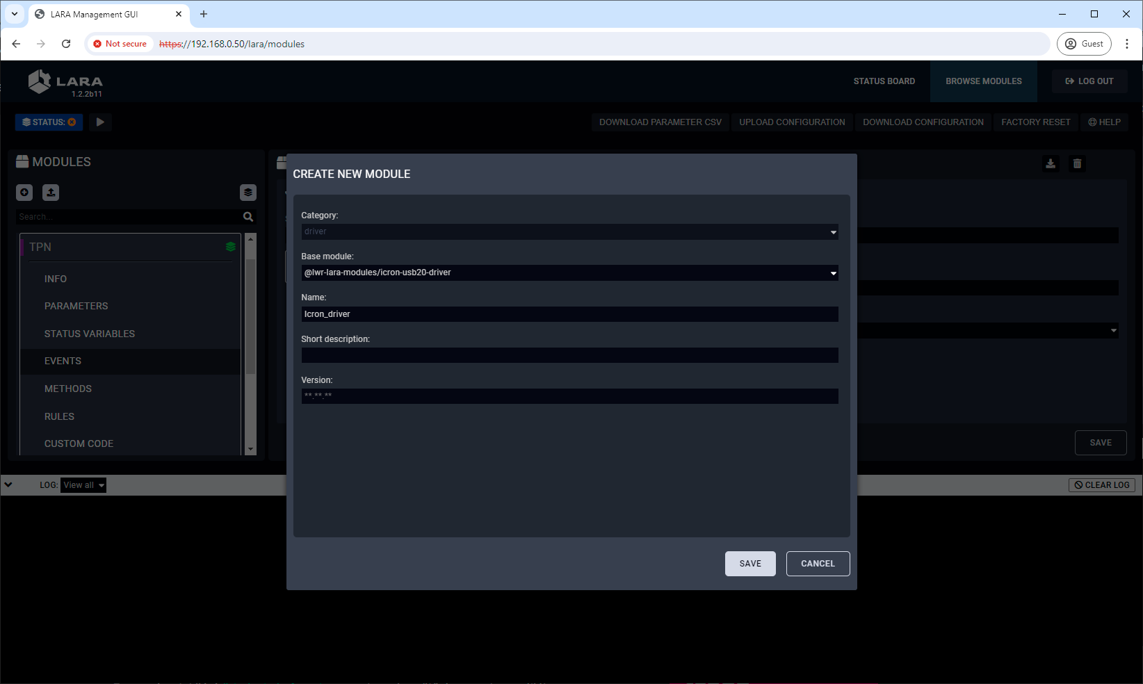
Step 4.Click on the Save button to complete the driver module.
6.3.2. Creating an Instance from the Driver Module
An instance is needed to be created from the driver module as follows:
Step 1.Click on the button to create an instance.
Step 2.Fill out the parameters of the new instance as follows:
=Instance name: a custom name (note down the given name, it must be used later)
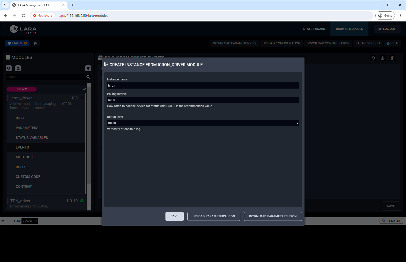
Step 3.Click on the Save button to complete the instance.
6.3.3. Creating the Userpanel Module
Users need a UI where the crosspoint settings can be managed.
Step 1.Navigate to the Browse Modules tab.
Step 2.Click on the button to create a new module.
Step 3.Fill out the parameters of the new module as follows:
=Category: userpanel
=Template: Icron small room
=Name: a custom name
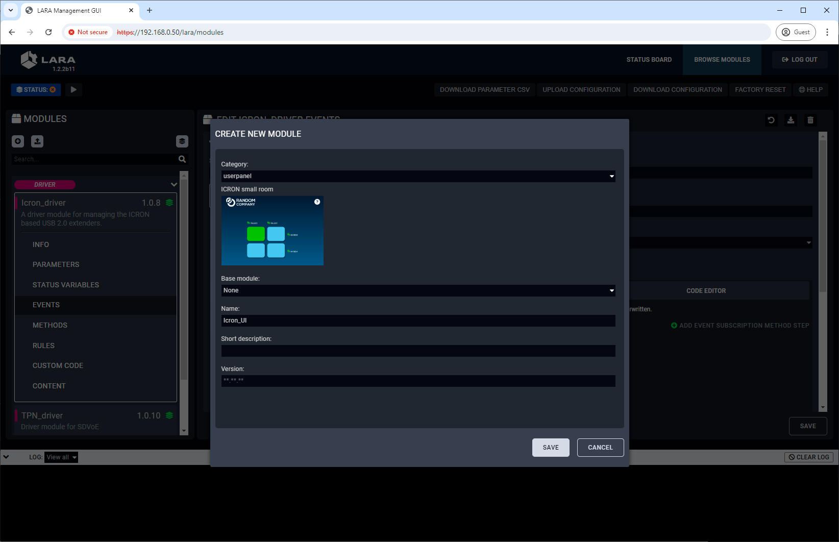
Step 4.Click on the Save button to complete the driver module.
TIPS AND TRICKS:The built-in templates can be customized freely and users can add new buttons and features to the touchpanel as well. See more personalization samples in the Personalizing of the UI section.
6.3.4. Creating an Instance from the Userpanel Module
An instance is needed to be created from the userpanel module as follows:
Step 1.Click on the button to create an instance.
Step 2.Fill out the parameters of the new instance as follows:
=Instance name: a custom name
=sdvoeInstanceId: the name of the instace created from the driver
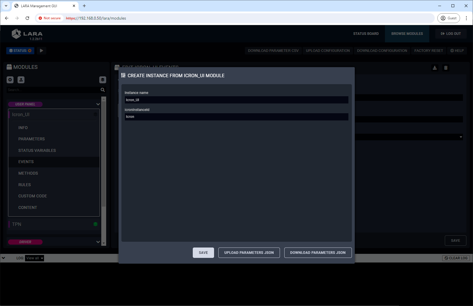
Step 3.Click on the Save button to complete the instance.
6.3.5. Starting of the LARA Services
LARA services need to be started by clicking on the button.
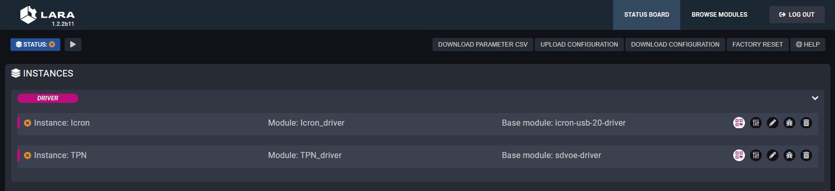
Services are not running in LARA
After the services start to run, the status board displays the details of the services.
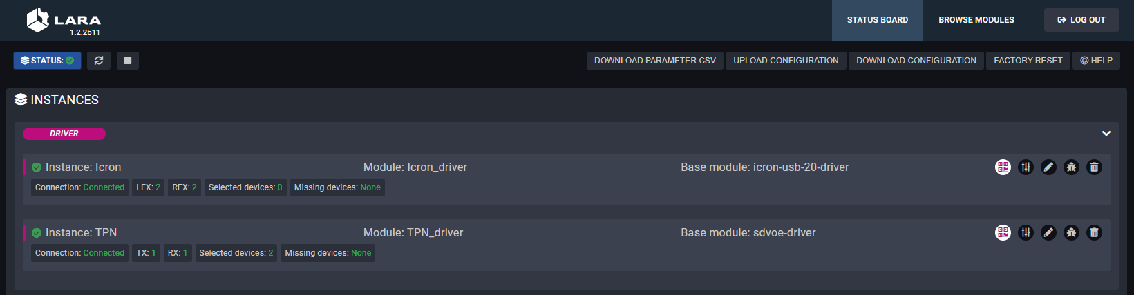
Services are running in LARA
The services can be stopped by clicking on the button and they can be restarted by clicking on the button.
Information on the Driver Status Board
|
Field |
Value |
Description |
|---|---|---|
|
Connection |
Connected |
TPN-CTU-X50 is online and managed by the LARA services. |
|
Disconnected |
TPN-CTU-X50 is not connected to the LARA services. |
|
|
LEX |
<number> |
Number of the connected AU2K series transmitters. |
|
REX |
<number> |
Number of the connected AU2K series receivers. |
|
Selected devices |
<number> |
Number of selected AU2K series extenders in the Icron UI panel. |
|
Missing devices |
<number> |
Number of selected AU2K series extenders in the Icron UI panel that are disconnected from the network. |
6.3.6. Configuration of the UI
Accessing of the Icron GUI
Click on the icon in the status board of the Icron USB 2.0 driver.
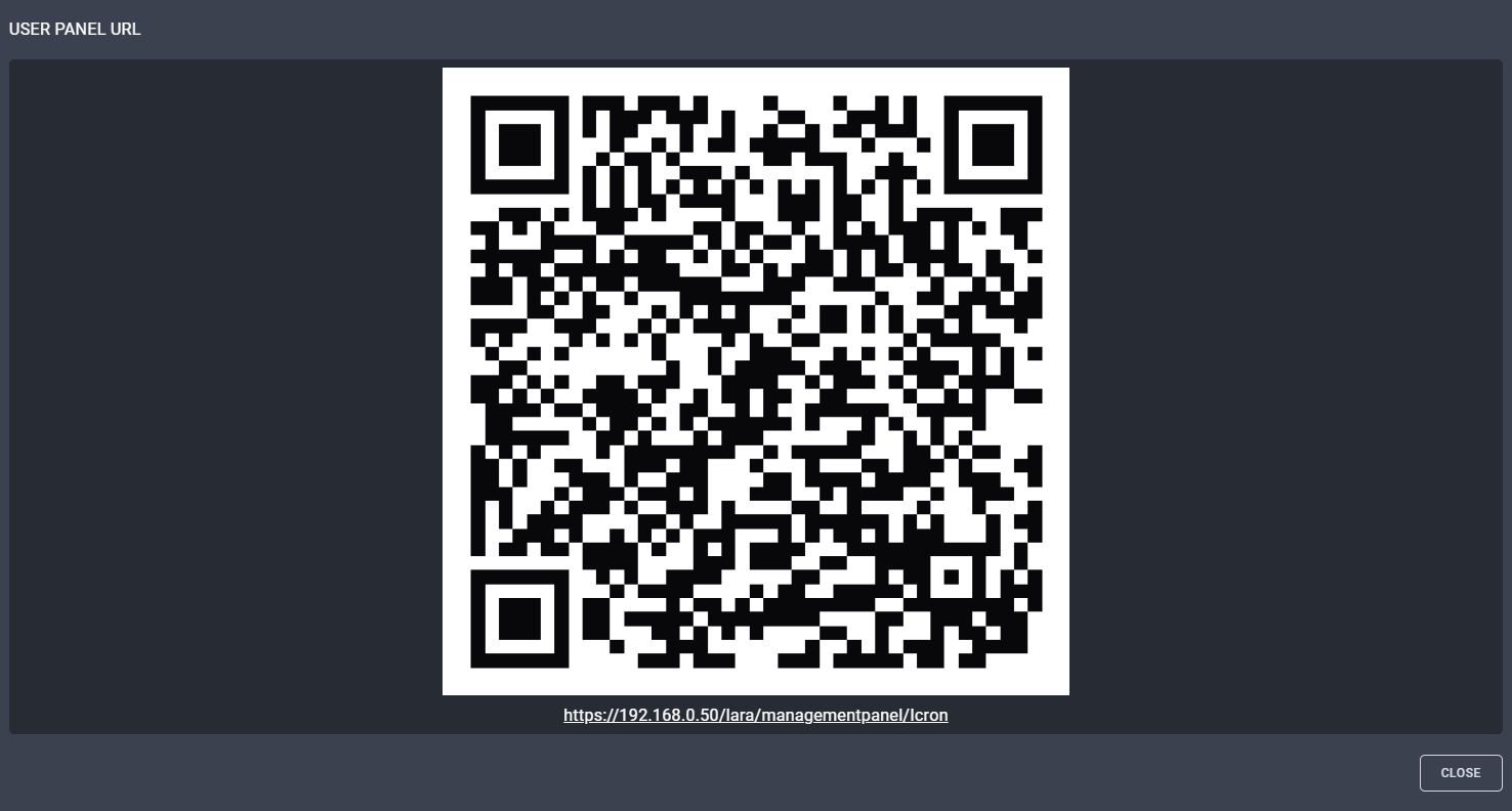
QR code and the direct link to the UI of the driver
Configuration of the Endpoint Devices with Icron GUI
Open the link that guides to the Icron GUI where the transmitters (Local - LEX) and the receivers (Remote - REX) can be managed and the crosspoint table can be built.
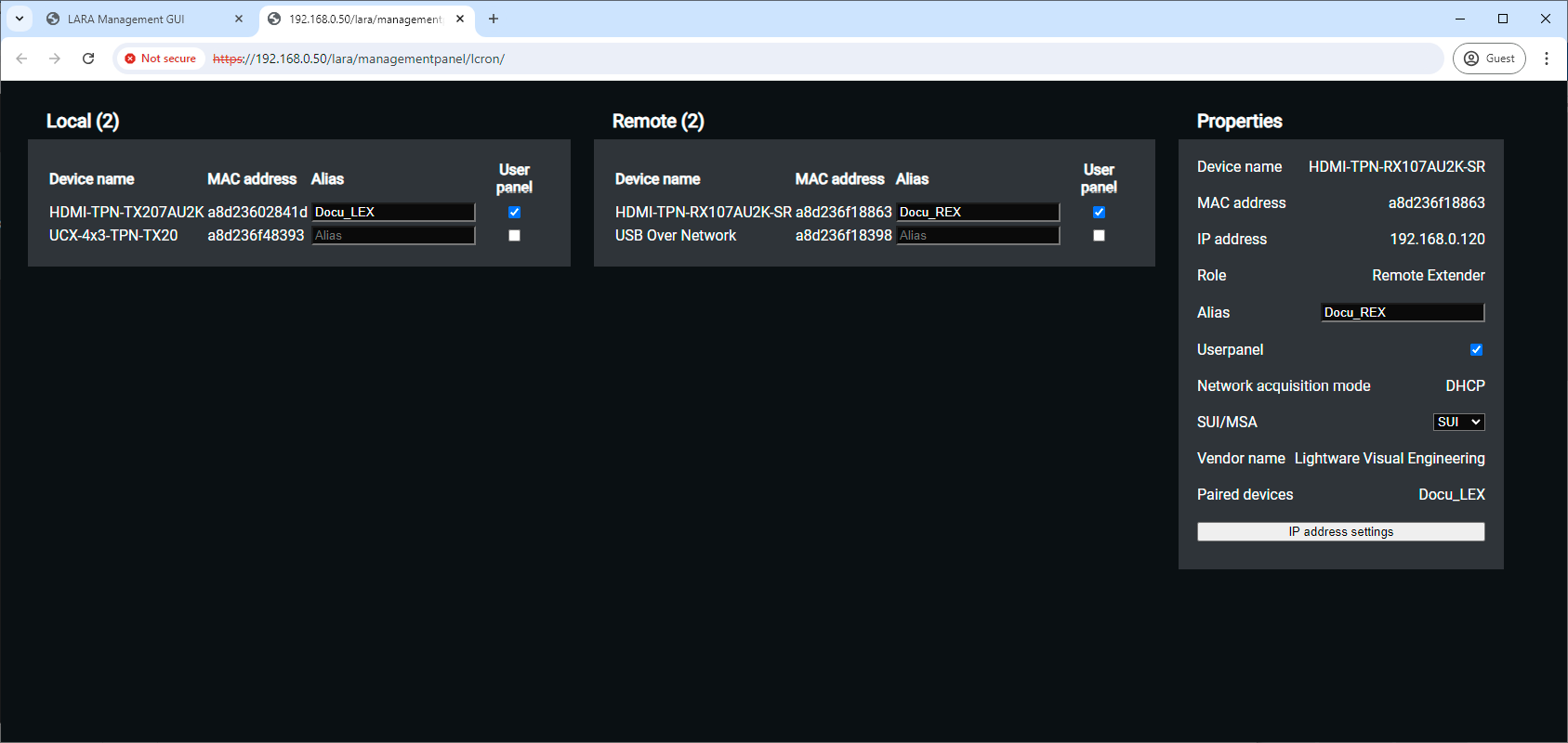
TPN GUI window
Description
The default device name of the endpoints is the ID of the device. It can be personalized in the Custom name field. Where the User panel checkbox is ticked in, the stream of the endpoint will appear on the Userpanel as a crosspoint possibility.
Select an endpoint device to check the parameters in the Properties section. The panel displays information about the IP address and MAC address of the Icron module in the AU2K series endpoint device. Alias can be defined for easier recognition in the crosspoint table.
SUI / MSA setting:
▪SUI - Simultaneous Users Interaction - this mode is recommended in case of point-multipoint connections (multiple REXes are connected to a single LEX).
▪MSA - Mass Storage Acceleration
Crosspoint View on the Icron Userpanel
Click on the icon in the status board of the Icron userpanel:
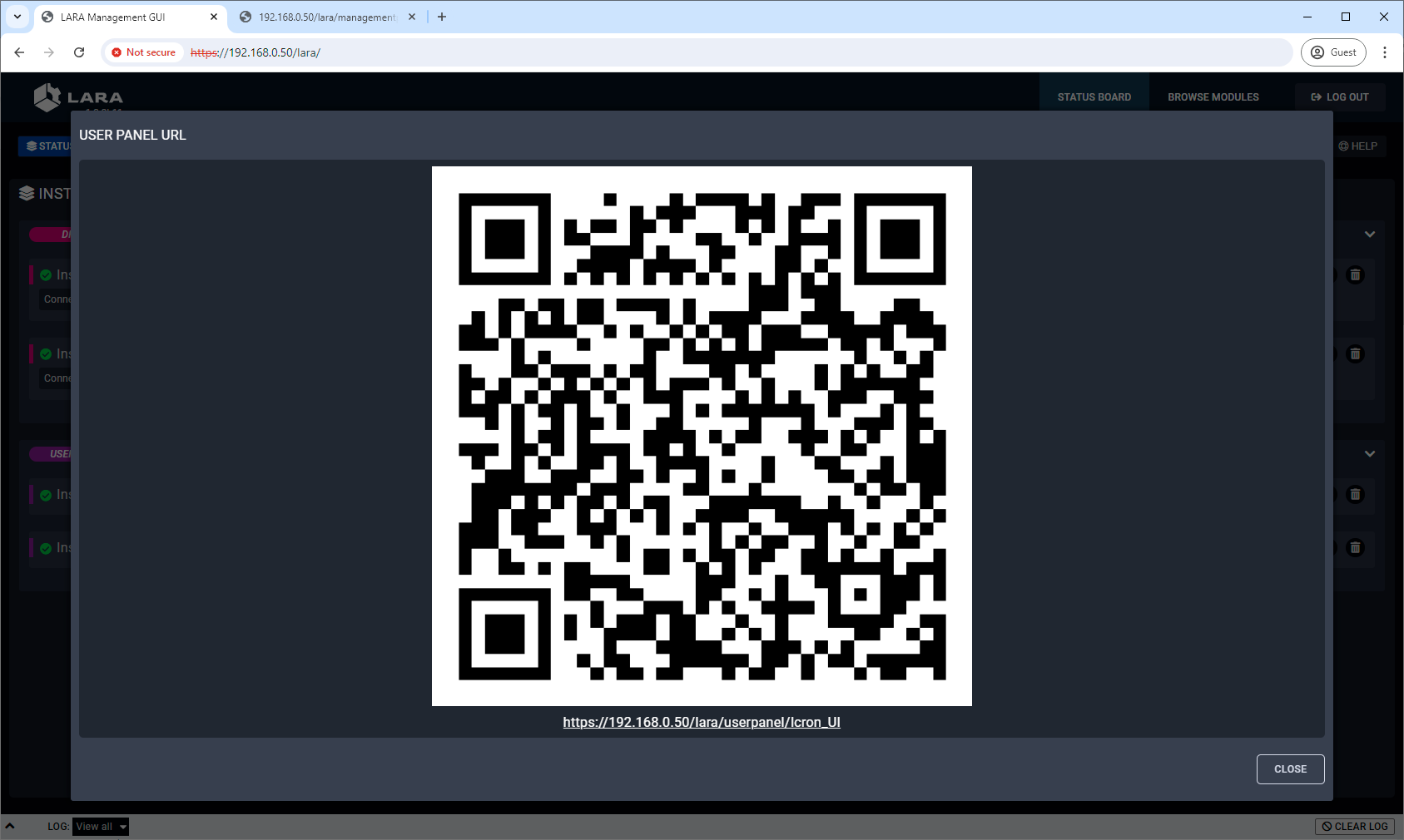
QR code and the direct link to the userpanel
Open the link that guides to the user panel where the crosspoint settings can be managed.
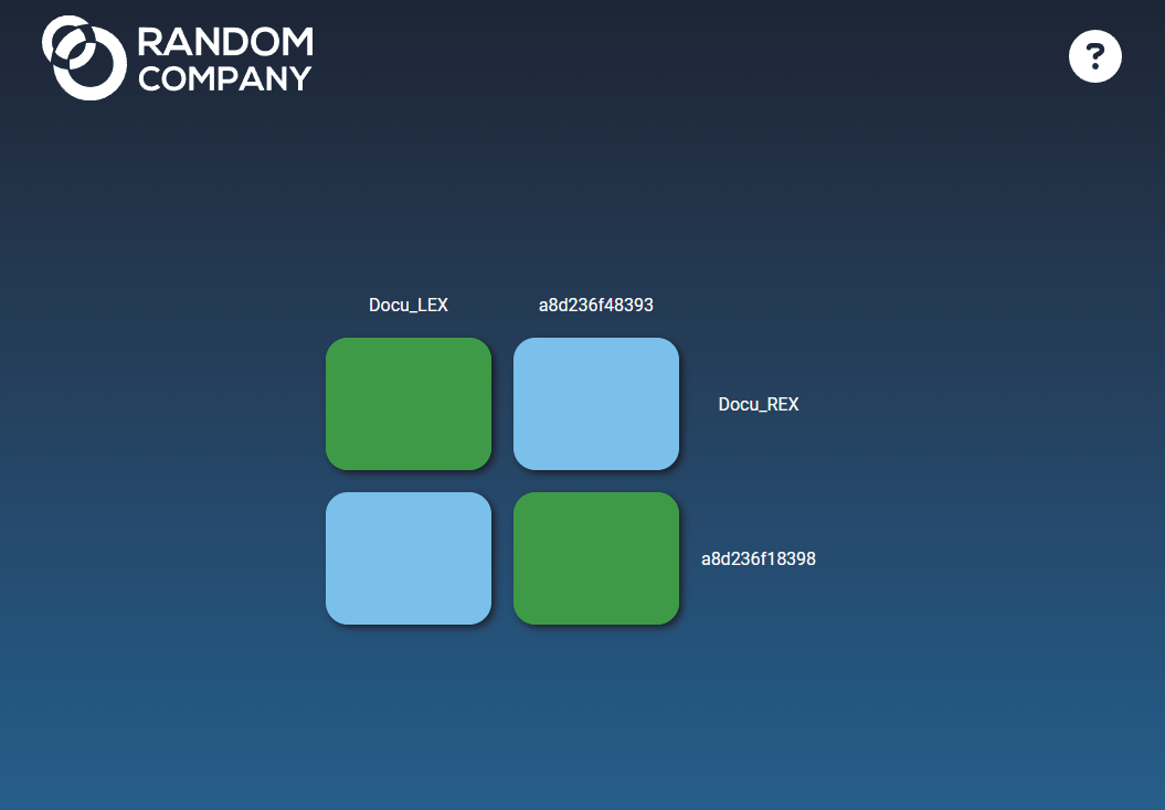
Crosspoint UI of a sample 2x2 Icron USB 2.0 matrix system
7. Android and iPad Kiosk Mode for LARA
The chapter is a guide showing how to turn an Android or iPadOS-based touchscreen to a kiosk that runs LARA control interface.
7.1. Introduction
DEFINITION:A digital kiosk is a standalone, screen-based computer terminal that provides information, services, or products to users independently, often with an interactive touchscreen, for self-service and engagement.
Devices controlled by LARA can be supervised by user interfaces (see more details about it in the Touchscreen UI Module section) that usually operates on touchscreen-based devices. This chapter guides the steps and provides useful tips on how you can make a kiosk from an Android- or iPadOS-based touchscreen device.
Advantage of the Kiosk Mode
Android devices and iPads are multifunctional computers, but the kiosk mode prevents unauthorized users from launching other applications on the touchscreen. This mode turns the touchscreen to a dedicated LARA control panel.
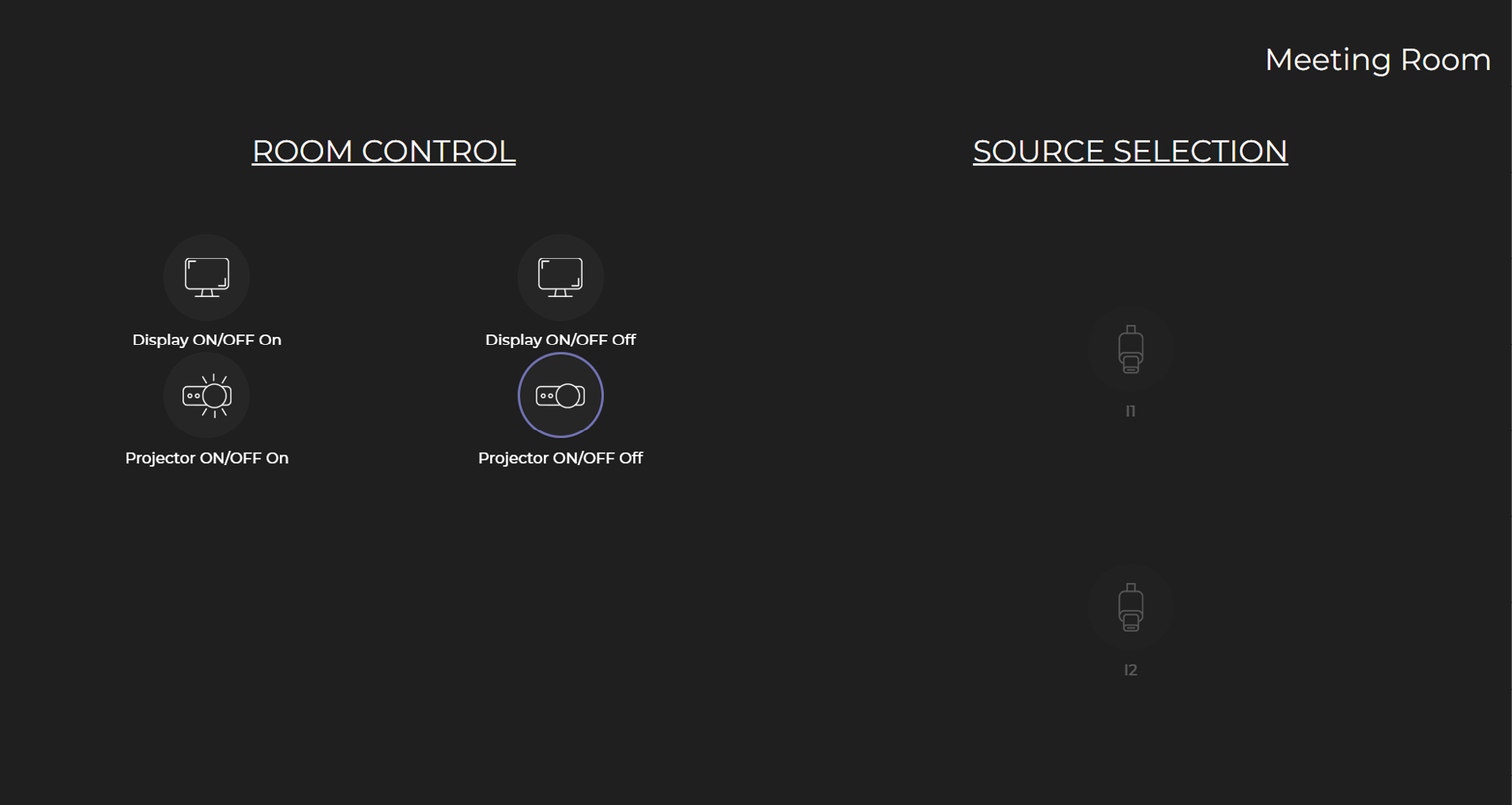
HP Poly touch control on an Android device in kiosk mode
7.2. Kiosk Mode for Android
DIFFERENCE:The following guide can be applied to touchscreen devices installed with Android OS only.
7.2.1. Kiosk Application
The kiosk mode requires a specific application installed on the Android touchscreen device. Lightware recommends the Fully Kiosk Browser that can be downloaded from Google Play application store or the .apk installation file from the provider's website. It is a freeware and easy-to-use application that is able to turn your Android device to a kiosk.
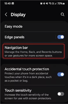
INFO:The following features are avaible in the free version as well. If extra features are required, they are available in the paid (PLUS) version only.
7.2.2. Preparation for the Kiosk Mode
Hide the Status Bar
The best mode running a kiosk application on the tourchscreen device is hiding the status bar and the bottom control buttons. It is for the purpose of preventing unauthorized users exit from the kiosk mode or launching other applications on the device.
After the installation of Fully Kiosk Browser, navigate to the Settings -> Display -> (Advanced) -> Navigation bar -> Hide status bar option and enable it: .
Disable the Screen Timeout
Navigate to the Settings -> Display -> (Advanced) -> Navigation bar -> Screen timeout option and set to Never.
7.2.3. Configuration of the Kiosk Application
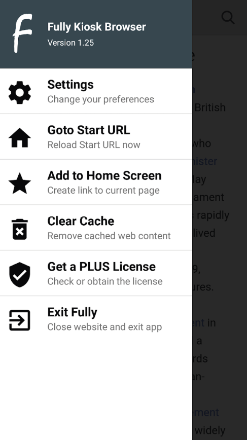
Set the URL of the LARA UserPanel Module
Launch the Fully Kiosk Browser. Navigate to the Settings (swipe on the left side of the touchscreen). Select the Web Content Settings -> Start URL submenu. Type the URL of the LARA UserPanel module:
http://<ip_address>/lara/userpanel/...
Learn more details about how to find the URL of your LARA user module in the Dashboard and Personalization section.
Extra Features for Kiosk Mode
DIFFERENCE:This setting is available in the PLUS (licensed) version only.
INFO:The kiosk functionality without security features (like lockdown) is working in the free version as well.
Navigate to the Settings (swipe on the left side of the touchscreen). Select the Kiosk Mode (PLUS) -> Enable Kiosk Mode option. Kiosk mode PIN can be set for the full lockdown of the device.
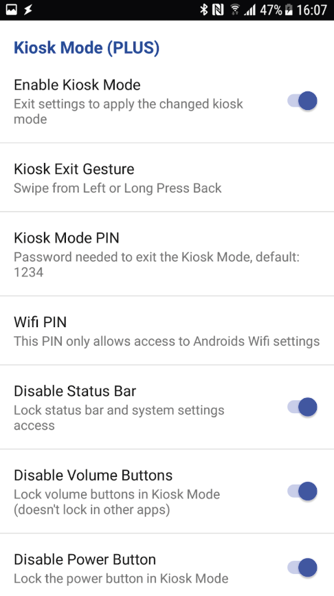
Kiosk Mode setting in the Fully Kiosk Browser application
7.3. Kiosk Mode for iPadOS
DIFFERENCE:The following guide can be applied to touchscreen devices installed with iPadOS only.
7.3.1. Kiosk Mode in iPad
iPad kiosk mode locks the device to a single app and restricts hardware functions, allowing you to set it up for specific, controlled use. You can enable kiosk mode using the built-in Guided Access feature, which requires triple-clicking the Home button to start and a passcode to exit, or by using Single App Mode (SAM) via Mobile Device Management (MDM) for supervised devices and larger deployments.
Methods for Kiosk Mode
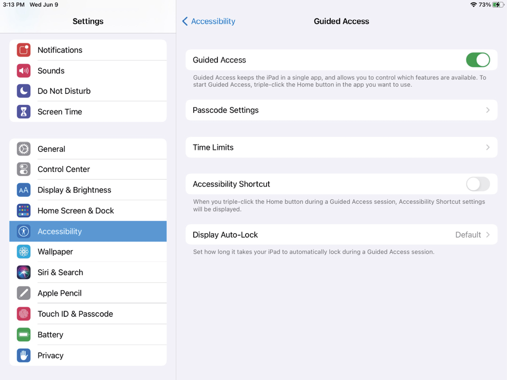
There are two main ways to enable kiosk-style functionality on iPads:
Guided Access (Built-in, Simple Kiosk Mode)
▪Found under Settings -> Accessibility -> Guided Access.
▪Allows you to lock the iPad into one app only.
▪You can also:
=Disable touch in certain screen areas.
=Turn off hardware buttons (home, volume, sleep).
=Control time limits.
▪Exit requires a passcode or Face/Touch ID.
▪Best for quick setups, temporary use, or personal devices.
Detailed description with the required configuration steps is available in the Guided Access Setup on iPad section.
Single App Mode (Enterprise-grade Kiosk Mode)
▪Requires Apple Business Manager (ABM) or Apple School Manager (ASM) and a Mobile Device Management (MDM) solution.
▪Locks the iPad permanently into a single app until the MDM profile is removed or updated.
▪Can control:
=Network settings.
=Screen auto-lock.
=App availability and updates.
▪More secure and hands-off than Guided Access.
▪Used for large deployments (e.g., self-check-in kiosks, POS systems).
Detailed description with the required configuration steps is available in the Single App Mode on iPad (Enterprise Kiosk) section.
7.3.2. Guided Access Setup on iPad
This section describes how to set up Guided Access on iPad.
Step 1.Enable Guided Access.
▪Open Settings.
▪Go to Accessibility -> Guided Access (under the General section).
▪Toggle Guided Access ON .
▪Tap Passcode Settings and set a passcode (or allow Face ID / Touch ID) — this is what will be used to exit kiosk mode.
Step 2.Start a Guided Access Session.
▪Open the web browser (e.g. Safari) with the URL of LARA user module you want to lock the iPad into. (See more details about how to find the URL of your LARA user module in the Dashboard and Personalization section.)
▪Triple-click the Home button (or the Top button on iPads without a Home button).
▪The Guided Access menu will appear.
▪Here you can:
=Disable areas of the screen (circle parts of the screen to block touch input).
=Turn off buttons like Sleep/Wake, Volume, Motion, Keyboards, etc.
=Set a time limit if needed.
▪Tap Start (top right) — now the iPad is locked to the web browser.
Step 3.End Guided Access.
▪Triple-click the Home / Top button.
▪Enter your passcode (or use Face ID / Touch ID).
▪Tap End.
7.3.3. Single App Mode on iPad (Enterprise Kiosk)
Requirements
Step 1.Supervised iPad — supervision means the iPad is enrolled through:
▪Apple Business Manager (ABM) or Apple School Manager (ASM), and
▪enrolled into an MDM (Mobile Device Management) system. (Examples: Jamf, Intune, Mosyle, Kandji, Hexnode, Miradore, etc.)
Step 2.The web browser application (e.g. Safari) you want to run in kiosk mode must already be installed on the device.
Steps to Enable Single App Mode
Step 1.Enroll the iPad into MDM.
▪Set up ABM/ASM, connect it to your MDM.
▪During device setup, assign the iPad to your MDM profile.
Step 2.Supervise the Device.
▪Devices enrolled through ABM/ASM are automatically supervised.
▪If it’s a manual setup, you can supervise using Apple Configurator.
Step 3.Push a Single App Mode Policy.
▪In your MDM console, find the Restrictions or Kiosk settings.
▪Choose Single App Mode (sometimes called "App Lock").
▪Select the web browser application you want locked (e.g., Safari).
▪Push the policy to the supervised iPad.
Step 4.Device Behavior.
▪The iPad reboots (sometimes required).
▪It boots directly into the selected app.
▪Home button, multitasking, and Control Center are disabled.
▪The user cannot exit the app — only MDM can change it.
Updating / Changing Apps
▪To switch the kiosk app, update the MDM profile and push it again.
▪You can also schedule downtime, manage Wi-Fi settings, disable auto-lock, or block gestures via MDM.
8. Updating LARA via LDU2 Software
The chapter describes the updating steps of LARA software only on the Taurus UCX product line via the Lightware Device Updater V2 (LDU2) software.
ATTENTION!LARA-only updating via LDU2 software is available from LARA v2.0.0 and LUD2 v2.36.0 only.
8.1. Introduction
![[Alt text was not generated.]](UM-web-resources/image/LDU_packages.png)
Lightware Device Updater V2 (LDU2) software is the second generation of the LFP-based (Lightware Firmware Package) firmware update process.
8.2. Important Notes
ATTENTION!When factory default settings are recalled or configuration clone (backup & restore) is applied on the device, the original LARA software version will be restored what is contained in the firmware package. See more details about the original LARA versions in the firmware packages in the LARA Versions in the Firmware Packages section.
8.3. Preparation
Most Lightware devices can be controlled over several interfaces (e.g. Ethernet, USB, RS-232). But the firmware can be updated usually over one dedicated interface, which is the Ethernet in most cases.
If you want to update the firmware of one or more devices, you need the following:
▪LFP2 file - it can be downloaded from the Downloads section of LARA website;
▪LDU2 software installed on your PC or Mac - it can be downloaded from the dedicated website of LDU2.
8.3.1. About the Firmware Package (LFP2 File)
All the necessary tools and binary files are packed into the LFP2 package file. You only need this file to do the update on your device.
▪This allows the use of the same LFP2 package for different devices.
▪The package contains all the necessary components, binary, and other files.
▪The release notes is included in the LFP2 file, which is displayed in the window where you select the firmware package file in LDU2.
INFO:The size of the LFP2 file is more than 200 MB due to the components of the package. That is not a fault: Taurus runs embedded Linux inside that is necessary for the complex functions and features of the device.
8.3.2. LDU2 Installation
ATTENTION!Minimum system requirement: 2 GB RAM. The minimum display resolution is 1600x900.
INFO:The Windows and the Mac applications have the same look and functionality.
Download the software from www.lightware.com.
Installation in case of Windows OS
Run the installer. If the User Account Control displays a pop-up message, click Yes.
Installation Modes
|
Normal install |
Snapshot install |
|
Available for Windows, MacOS and Linux |
Available for Windows |
|
The installer can update only this instance |
Cannot be updated |
|
One updateable instance may exist for all users |
Many different versions can be installed for all users |
ATTENTION!Using the default Normal install is highly recommended.
INFO:If you have a previously installed version, you will be prompted to remove the old version before installing the new one.
Installation in case of macOS
Mount the DMG file by double clicking on it, and drag the LDU2 icon over the Applications icon to copy the program into the Applications folder. If you want to copy LDU2 into another location, just drag the icon over the desired folder.
ATTENTION!Please check the firewall settings on the macOS device. LDC needs to be added to the exceptions of the blocked software for the proper operation.
INFO:This type of installer is equal to the Normal install of Windows.
Installation in case of Linux
![[Alt text was not generated.]](UM-web-resources/image/507px-Tux.svg.png)
Step 1.Download the archive file (tar.gz) from www.lightware.com and unpack it to a temp folder.
Step 2.Run the install_ldu2.sh file in the temp folder. The script will install LDU2 into the following folder: HOME/.local/share/lightware/ldu2.
Step 3.The folder above will contain this file: LightwareDeviceUpdaterV2.sh, which can be used to start LDU2.
8.4. Affected Lightware Devices
8.4.1. Supported Models
The following devices can be updated with LARA over LDU2. The LARA-only updating is supported from the following firmware package only.
|
Model family |
Model |
From firmware package |
|---|---|---|
|
UCX-HC30 series switchers |
UCX-2x1-HC30 |
v2.16.1b2 |
|
UCX-2x2-H30 |
||
|
UCX-4x2-HC30 |
||
|
UCX-4x2-HC30D |
||
|
UCX-HC40 series switchers |
UCX-1x1-C40 |
v2.22.0b1 |
|
UCX-2x1-HC40 |
||
|
UCX-2x2-H40 |
||
|
UCX-4x2-HC40 |
||
|
UCX-4x3-HC40 |
||
|
UCX-4x2-HC40D |
||
|
UCX-4x3-HC40-BD |
||
|
DCX-HC20 series switchers |
DCX-2x1-HC10 |
|
|
DCX-3x1-HC20 |
||
|
UCX-HC60 series switchers |
UCX-1x1-C60 |
v2.21.0b2 |
|
UCX-2x1-HC60 |
||
|
UCX-2x2-H60 |
||
|
UCX-4x2-HC60 |
||
|
UCX-4x3-HC60 |
||
|
UCX-4x2-HC60D |
||
|
UCX-4x3-HC60-BD |
||
|
DCX-HC21 series switchers |
DCX-3x1-HC21 |
|
|
Dualscreen Taurus |
UCX-4x3-HCM40 |
v1.3.0b5 |
|
Taurus TPX series transmitters |
UCX-4x3-TPX-TX20 |
v1.19.0b1 |
|
UCX-2x1-TPX-TX20 |
||
|
DCX-3x1-TPX-TX10 |
||
|
Taurus TPN series transmitters |
UCX-4x3-TPN-TX20 |
|
|
UCX-2x1-TPN-TX20 |
||
|
DCX-3x1-TPN-TX10 |
||
|
Taurus TPX receiver |
UCX-3x3-TPX-RX20 |
v1.8.0b1 |
|
TPN-CTU |
TPN-CTU-X50 |
v1.5.0b5 |
|
MMX2 series switchers |
MMX2-4x1-H20 |
v2.13.0b3 |
|
MMX2-4x3-H20 |
8.4.2. LARA Versions in the Firmware Packages
ATTENTION!When factory default settings are recalled or configuration clone (backup & restore) is applied on the device, the original LARA software version will be restored what is contained in the firmware package.
UCX-HC40 and DCX Series Switchers
|
Affected models |
Firmware package version |
LARA version in the firmware package |
|---|---|---|
|
UCX-1x1-C40 UCX-2x1-HC40 UCX-2x2-H40 UCX-4x2-HC40 UCX-4x3-HC40 UCX-4x2-HC40D UCX-4x3-HC40-BD DCX-2x1-HC10 DCX-3x1-HC20 |
v2.18.0b5 |
v1.3.0 |
|
v2.19.0b1 |
v1.3.1 |
|
|
v2.20.0b4 |
||
|
v2.20.1b3 |
||
|
v2.21.0b2 |
Dualscreen Taurus
|
Affected models |
Firmware package version |
LARA version in the firmware package |
|---|---|---|
|
UCX-4x3-HCM40 |
v1.3.0b5 |
v1.3.0 |
|
v1.4.0b1 |
v1.3.1 |
Taurus TPX and TPN series Transmitters
|
Affected models |
Firmware package version |
LARA version in the firmware package |
|---|---|---|
|
UCX-4x3-TPX-TX20 UCX-2x1-TPX-TX20 DCX-3x1-TPX-TX10 UCX-4x3-TPN-TX20 UCX-2x1-TPN-TX20 DCX-3x1-TPN-TX10 |
v1.18.0b6 |
v1.3.1 |
|
v1.18.1b1 |
Taurus TPX Receiver
|
Affected models |
Firmware package version |
LARA version in the firmware package |
|---|---|---|
|
UCX-3x3-TPX-RX20 |
v1.5.0b5 |
v1.3.0 |
|
v1.6.0b1 |
v1.3.1 |
|
|
v1.7.0b4 |
TPN-CTU Controller Unit
|
Affected models |
Firmware package version |
LARA version in the firmware package |
|---|---|---|
|
TPN-CTU-X50 |
v1.5.0b5 |
v1.3.0 |
|
v1.6.0b2 |
v1.3.1 |
|
|
v1.7.0b4 |
MMX2 series Switchers
|
Affected models |
Firmware package version |
LARA version in the firmware package |
|---|---|---|
|
MMX2-4x1-H20 MMX2-4x3-H20 |
v2.13.0b5 |
v1.3.0 |
|
v2.14.0b1 |
v1.3.1 |
8.5. Running LDU2
ATTENTION!The computer that runs LDU2 and the target device (that will be updated) must be in the same subnet. The update cannot be performed behind a firewall or gateway.
You have two options:
▪Starting the LDU2 by double-clicking on the shortcut/program file, or
▪Double-clicking on an LFP2 file.
8.5.1. LDU2 Interfaces
The software can be used over:
▪The Graphical User Interface (GUI), or by
▪The Command Line Interface (CLI).
8.5.2. Main Screen

When the software is started by the shortcut, the device discovery screen appears. Press the Discover devices button to start finding the Lightware devices:
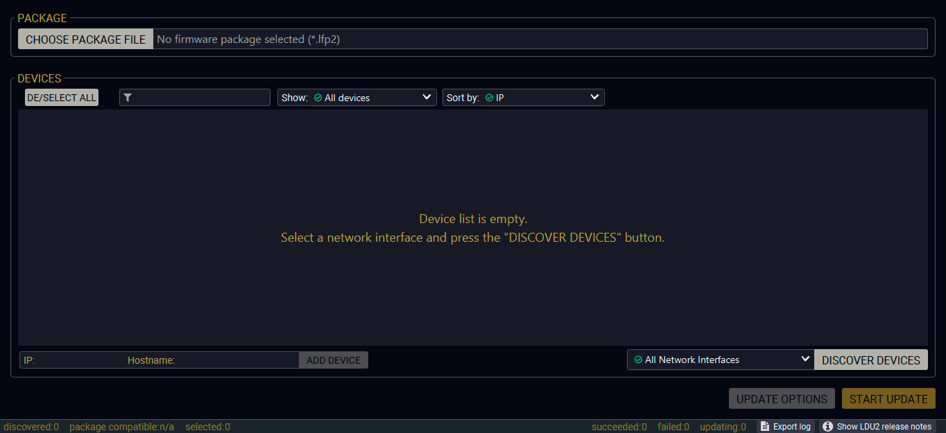
Startup screen of LDU2
Devices may also be added manually by typing the IP address in the box near the bottom of the screen. Manual addition of devices can also be done using the host name.
ATTENTION!If the device cannot be added by the host name, please use the IP address.
If you start the software by double-clicking on the LFP2 file, the firmware will be loaded. Press the Search for devices button; all the devices will be listed that are compatible with the selected firmware pack.
INFO:If you press the Choose package file button, the release notes of the LFP2 file will be displayed in the right panel; see the Step 1. Select the Firmware Package section.
Device List
When the discovery has completed, the devices available on the network are listed in the application.
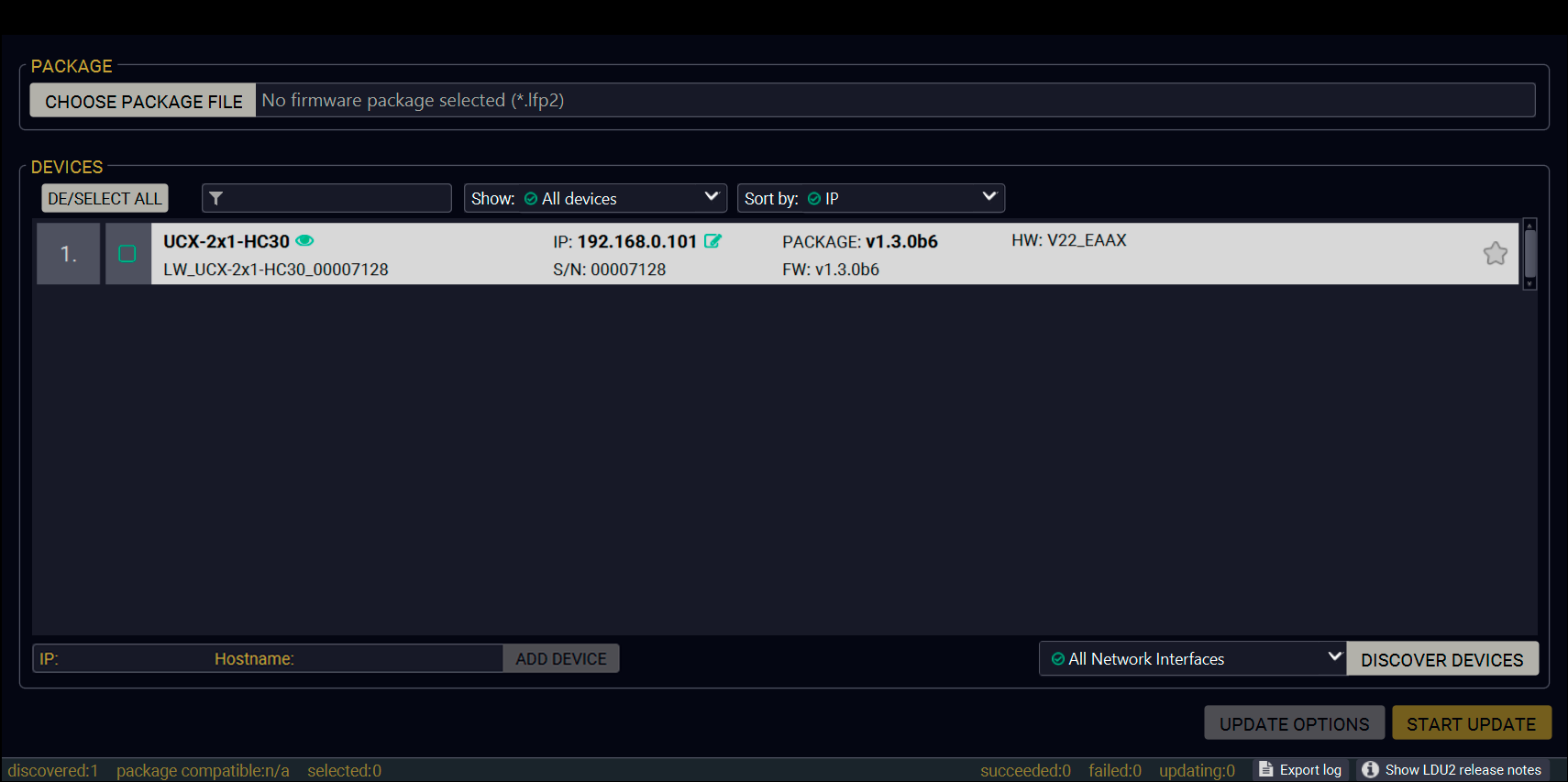
Device discovery window
Legend of the Icons
|
|
IP address editor |
The IP address of the device can be changed in the pop-up window. |
|
|
Identify me |
Clicking on the icon makes the front panel LEDs blink for 10 seconds, which helps identify the device physically. |
|
|
Authentication required |
The password-protection is enabled. You have to enter the password to perform the firmware update in the pop-up window at the beginning of the update. |

|
Favorite device |
The device has been marked, thus the IP address is stored. When a device is connected with that IP address, the star will be highlighted in that line. |

|
Further information available |
Device is unreachable. Change the IP address using built-in web / LDC or the IP address editor of the LDU2. |
8.6. Updating Via GUI
To update the desired device(s) via the Graphical User Interface, follow these steps.
ATTENTION!The computer that runs LDU2 and the target device (that will be updated) must be in the same subnet. The update cannot be performed from behind a firewall or gateway.
Step 1. Select the Firmware Package

Click on the Choose package file button and navigate to the location where the LFP2 file was saved. When you click on the name of the package, the preview of the release notes is displayed in the right panel.
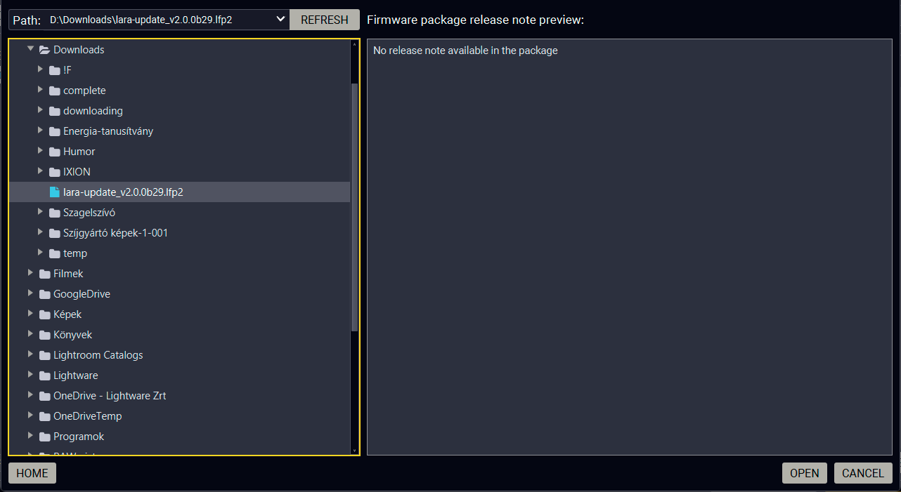
Package selector and release notes preview panel
After the package file is loaded, the list is filtered to show the compatible devices only. The current LARA version of the device is highlighted in orange if it is different from the version of the package loaded.
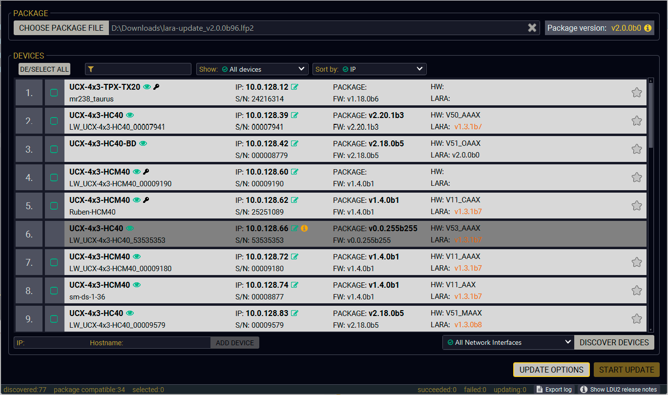
Discovery window filtered with the compatible devices
Step 2. Select the Desired Device(s) for Updating
Select the devices for updating; the selected line will be highlighted in green.
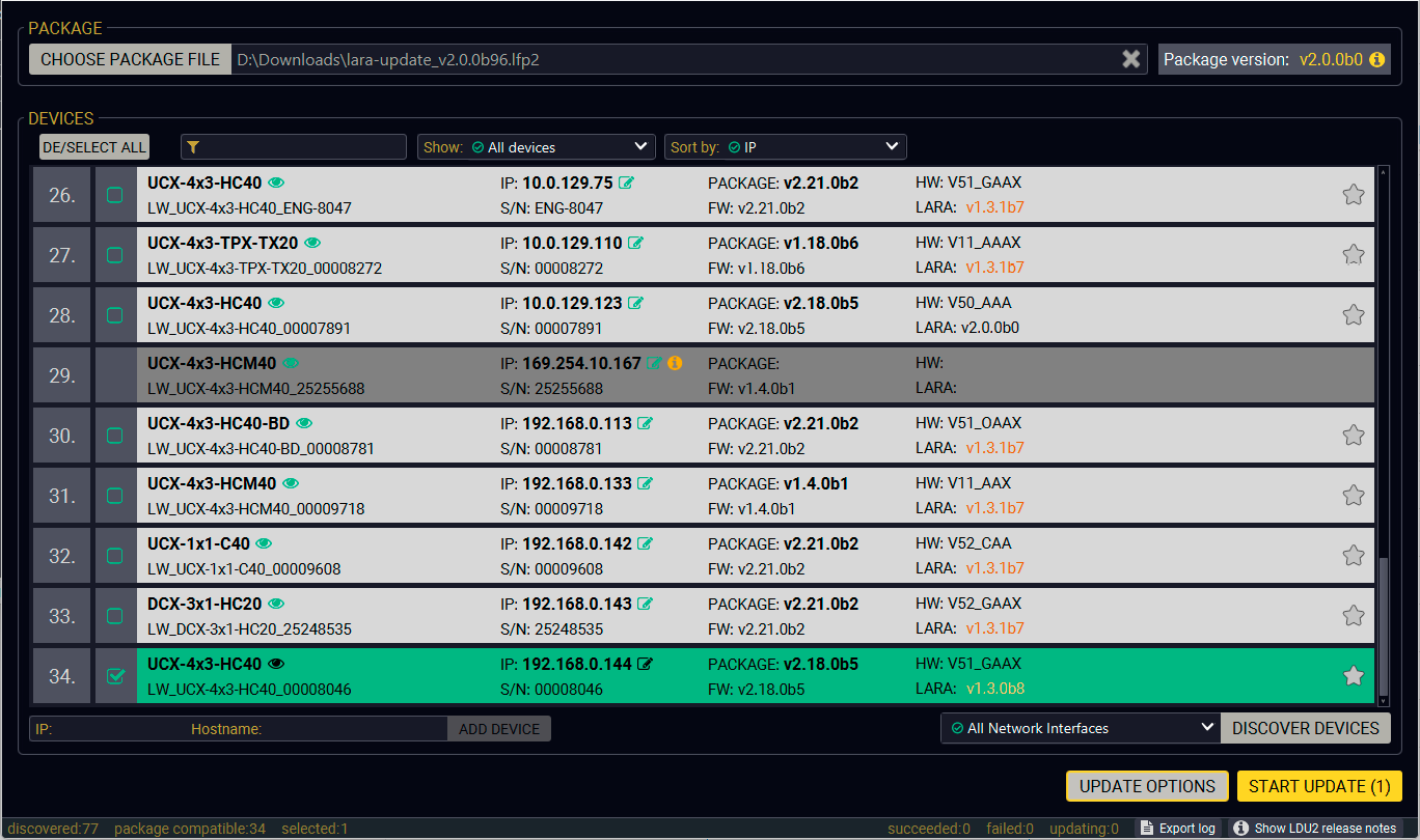
Discovery window with the selected device
Step 3. Check the Update Options
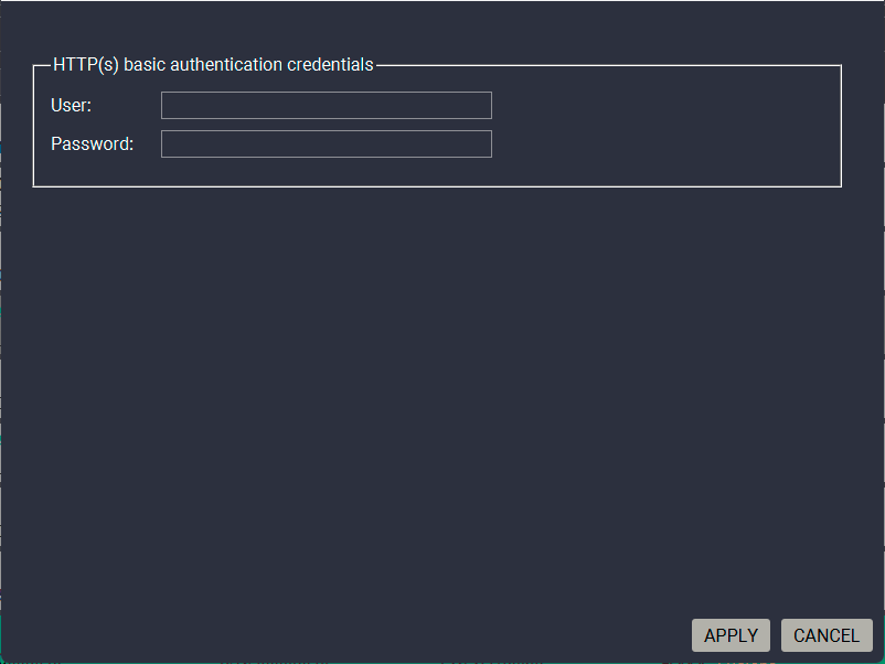
Pressing the Update options button on the bottom right corner pops up the HTTP(s) basic authentication credentials (user and password) fields.
ATTENTION!If basic authentication is set in the selected device, this option is required to be filled because of accessing the device by the software.
Step 4. Start the Update and Wait Until It Is Finished.
Click on the Start Update button to start the procedure. The status is shown in percent in the right side of the device line and the overall process in the bottom progress bar. The device might reboot during the firmware update procedure.
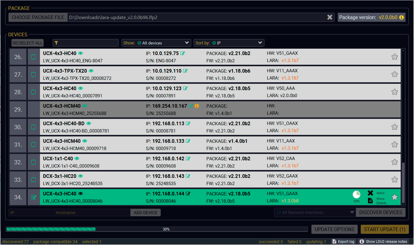
Update is in progress
When the progress bar reaches 100% (Done is displayed at all devices), the update of all devices are finished successfully and a message appears; you can close the software.
Step 5. Wait Until the Unit Reboots with the New Version of LARA
Once the LARA update procedure is completed, the device is rebooted.
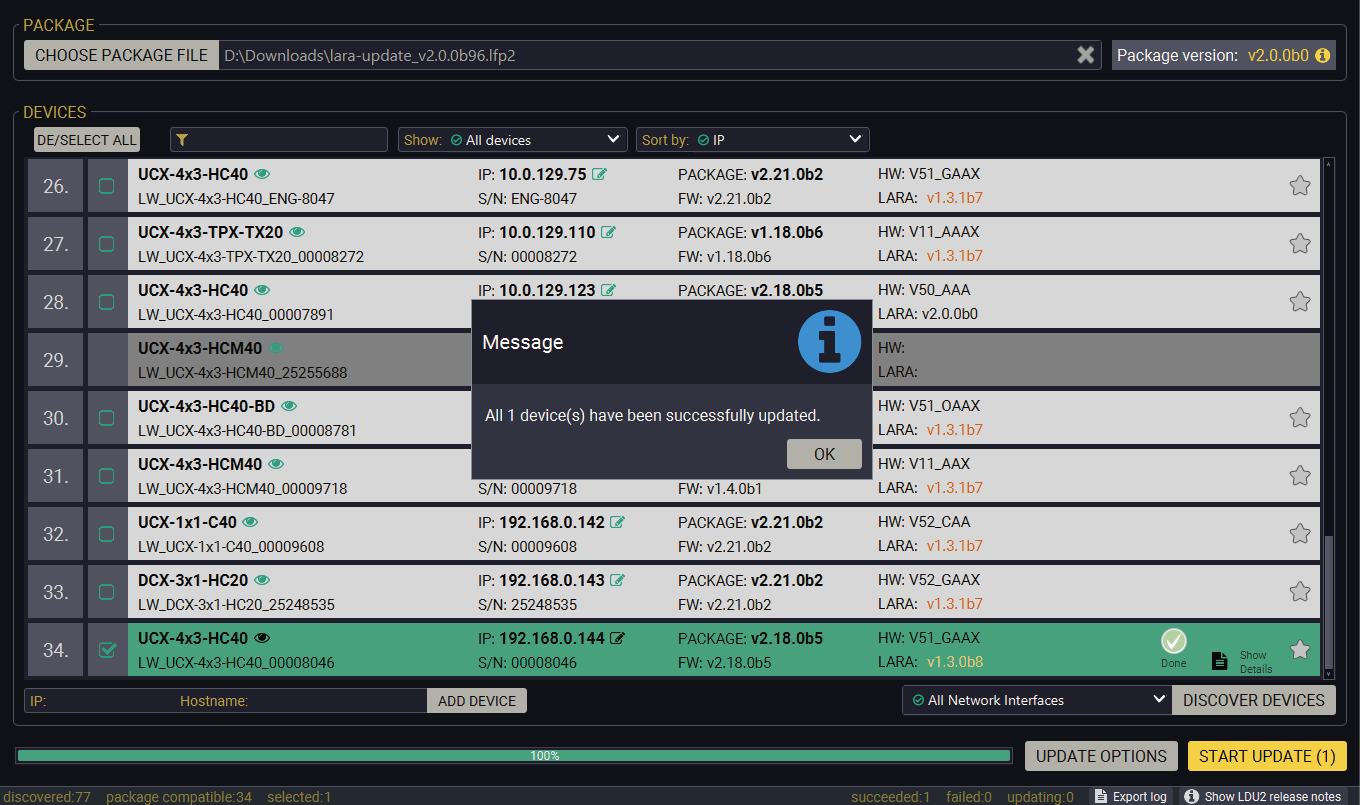
Update is completed successfully
8.7. Command Line Interface (CLI)
The CLI of the LDU2 software is a simple tool for creating scriptable device updates without the need of human interactions. It allows batch updating just like in case of GUI usage.
8.7.1. How to Run
Running under Windows® OS
The installer of LDU2 puts the following file into the installation folder:
LightwareDeviceUpdaterV2_CLI.cmd
CLI is available via this file, the exe is not suitable for that purpose. Open a command line window to execute or test the features directly.
Step 1.Open an Explorer window where the cmd file is located, the default is:
c:\Program Files (x86)\Lightware\Lightware Device Updater V2\LightwareDeviceUpdaterV2_CLI.cmd.
Step 2.Click on the address line (highlighted in blue in the picture), type cmd.exe and press enter. The command interpreter window of Windows is opened at the path of the LDU2 install folder.
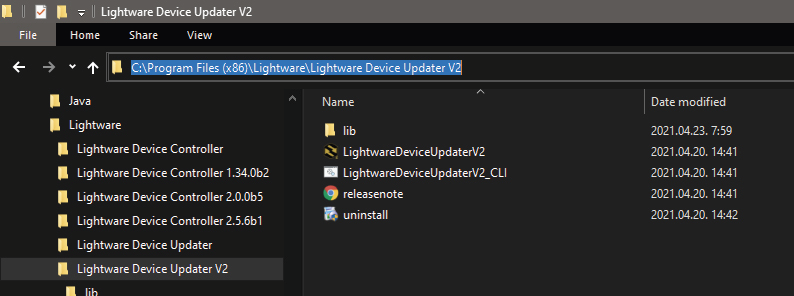
Step 3.Now you can use the LightwareDeviceUpdaterV2_CLI.cmd file with the commands and options, which are described in the coming sections:
Running under Linux
The Command Line Interface under Linux Operating Systems can be run by the following:
LightwareDeviceUpdaterV2.sh.
Running an update:
bash LightwareDeviceUpdaterV2.sh update --ip 172.24.5.27 --package ~/Downloads/taurus_v1.2.0b9.lfp2
The commands and options are the same under Windows® and Linux, too. Following sections contain examples with LightwareDeviceUpdaterV2_CLI.cmd.
8.7.2. How to Use
Command Structure
The commands can be run over CLI in the following way:
LightwareDeviceUpdaterV2_CLI.cmd [command] [options]
[Command]: a certain command described in the coming sections; only one command can be run at a time
[Options]: mandatory and/or optional parameters of the command, if any. Optional parameters have a default value, which can be found at each affected command. You only have to define the parameter if you want to apply a different value. The order of the options is arbitrary.
Important Notes
▪CLI is case-sensitive (including commands, options and other parameters).
▪There is no limit regarding the number of the devices to update. At most 20 devices are updated simoultaneously, when one of them is finished, the following (21st) will be started automatically.
▪If an update is failed, the IP address of the affected device(s) are listed at the end.
▪The computer that runs LDU2 and the target device (that will be updated) must be in the same subnet. The update cannot be performed from behind a firewall or gateway.
8.8. CLI Commands
INFO:The commands and options described in the following sections are the same under Windows® and Linux, too. The examples contain LightwareDeviceUpdaterV2_CLI.cmd.
About the Examples
▪Sent command is in blue, response is in grey.
▪If the response in practice is longer than listed in the example, this symbol can be seen: [...].
8.8.1. Help
The defined commands and options can be listed by the help command.
Command
LightwareDeviceUpdaterV2_CLI.cmd help
Example
C:\Program Files (x86)\Lightware\Lightware Device Updater V2>LightwareDeviceUpdaterV2_CLI.cmd help
C:\Program Files (x86)\Lightware\Lightware Device Updater V2>lib\jre\bin\java.exe -jar lib\ldu2.jar help
Command line usage:
Win: LightwareDeviceUpdaterV2_CLI.cmd [command] [options]
Linux: LightwareDeviceUpdaterV2.sh [command] [options]
Commands:
* help
* version
* update
* deviceInfo
* restore
* packageOptions
[...]
8.8.2. LDU2 Version
The response shows the version of the LDU2 and the version of the Script API (the Application Programming Interface that is used by the LDU2 and the script).
Command
LightwareDeviceUpdaterV2_CLI.cmd version
Example
C:\Program Files (x86)\Lightware\Lightware Device Updater V2>LightwareDeviceUpdaterV2_CLI.cmd version
C:\Program Files (x86)\Lightware\Lightware Device Updater V2>lib\jre\bin\java.exe -jar lib\ldu2.jar version
LDU2 version: 2.10.0b6
Script API version: 1.3.10
8.8.3. Check For New LDU2 Version
The following command can be used to check if an update of LDU2 is available. This is just a request, since the CLI is not suitable for handling the complete installer of the software.
Command
LightwareDeviceUpdaterV2_CLI.cmd checkForUpdates
Example 1
c:\Program Files (x86)\Lightware\Lightware Device Updater V2>LightwareDeviceUpdaterV2_CLI.cmd checkForUpdates
c:\Program Files (x86)\Lightware\Lightware Device Updater V2>lib\jre\bin\java.exe -jar lib\ldu2.jar checkForUpdates
Current LDU2 version: 2.36.0b8
LDU2 is up-to-date
Example 2
c:\Program Files (x86)\Lightware\Lightware Device Updater V2>LightwareDeviceUpdaterV2_CLI.cmd checkForUpdates
c:\Program Files (x86)\Lightware\Lightware Device Updater V2>lib\jre\bin\java.exe -jar lib\ldu2.jar checkForUpdates
Current LDU2 version: 2.10.0b6
New version is available online: 2.36.0b8
Download URL: http://update.lightware.hu/ldu2/lwr/v2.10.0b6/install_LDU2_v2.36.0b8.exe
8.8.4. Device Info
The most important information about the selected device is displayed; see the example for more details.
Command
LightwareDeviceUpdaterV2_CLI.cmd deviceInfo [options]
Options
|
Option |
Description |
Required? |
|
-i or --ip |
List of IP addresses of devices to be updated |
one of them is mandatory |
|
-n or --hostName |
List of host names of devices to be updated |
|
|
-v or --packageVersion |
Shows installed package version only |
optional |
Example 1
C:\Program Files (x86)\Lightware\Lightware Device Updater V2>LightwareDeviceUpdaterV2_CLI.cmd deviceInfo --ip 192.168.0.100
C:\Program Files (x86)\Lightware\Lightware Device Updater V2>lib\jre\bin\java.exe -jar lib\ldu2.jar deviceInfo --ip 192.168.0.100
Product name: UCX-4x2-HC40
IP address: 192.168.0.100
Serial number: 00006864
MAC address: a8:d2:36:F0:68:69
Part number: 91310088
Device label: LW_UCX-4x2-HC40_00006864
Package version: v2.18.0b3
CPU FW version: v2.18.0b3
HW version: V50_AXAX
Operation mode: Application mode
Example 2
C:\Program Files (x86)\Lightware\Lightware Device Updater V2>LightwareDeviceUpdaterV2_CLI.cmd deviceInfo --ip 192.168.1.7 --packageVersion
C:\Program Files (x86)\Lightware\Lightware Device Updater V2>lib\jre\bin\java.exe -jar lib\ldu2.jar deviceInfo --ip 192.168.0.100 --packageVersion
v2.18.0b3
8.8.5. Update
This command can be used to update the firmware of the devices.
Command
LightwareDeviceUpdaterV2_CLI.cmd update [options]
Options
|
Option |
Description |
Required? |
|
-p or --package |
The path of the LARA package file |
yes |
|
-i or --ip |
List of IP addresses of devices to be updated |
one of them is mandatory |
|
-n or --hostName |
List of host names of devices to be updated |
|
|
-r or --reportProgress |
Report update progress in percentage form. Default: false |
optional |
|
Package-specific options |
Certain LFP2 packages have features that can be applied at this command; see the Package Options section. |
optional |
ATTENTION!The configuration is restored automatically if the factory default option is not applied in the update command. In that case, there is no need to run the restore command after the update.
Example
C:\Program Files (x86)\Lightware\Lightware Device Updater V2>LightwareDeviceUpdaterV2_CLI.cmd update --ip 192.168.0.52 --package f:\LIGHTWARE\firmware\LARA_v2.0.0b37.lfp2 --reportProgress
C:\Program Files (x86)\Lightware\Lightware Device Updater V2>LightwareDeviceUpdaterV2_CLI.cmd update --ip 192.168.0.52 --package f:\LIGHTWARE\firmware\LARA_v2.0.0b37.lfp2 --reportProgress
C:\Program Files (x86)\Lightware\Lightware Device Updater V2>lib\jre\bin\java.exe -jar lib\ldu2.jar update --ip 192.168.0.52 --package f:\LIGHTWARE\firmware\LARA_v2.0.0b37.lfp2 --reportProgress
[2026-06-17 08:53:01.250] [ INFO] [ main] - Device IPs: [192.168.0.52]
[2026-06-17 08:53:09.075] [ INFO] [ main] - All the selected devices are accessible over the network.
[2026-06-17 08:53:11.097] [ INFO] [ main] - All the selected devices are compatible with the specified package.
[2026-06-17 08:53:15.067] [ INFO] [ 192.168.0.52] - Taurus UCX update process started
[2026-06-17 08:53:15.074] [ INFO] [ 192.168.0.52] - Update parameters: deviceIp: 192.168.0.52, factoryDefault: true
[2026-06-17 08:53:15.185] [ INFO] [ 192.168.0.52] - Update API version: 1.0
[2026-06-17 08:53:15.222] [ INFO] [ 192.168.0.52] - Update protocol: http://
[2026-06-17 08:53:15.223] [ INFO] [ 192.168.0.52] - Authentication type: BASIC
[2026-06-17 08:53:15.415] [ INFO] [ 192.168.0.52] - Device info: Product name: UCX-4x2-HC40, Device label: LW_UCX-4x2-HC40_00006869, Serial number: 00006869, Mac address: a8:d2:36:F0:68:69, Ip address: 192.168.0.52, Host name: , Package version: v2.18.0b3, Part number: 91310088, Hw version: V50_AXAX
[2026-06-17 08:53:15.450] [ INFO] [ 192.168.0.52] - Uploading firmware package.
[2026-06-17 08:53:16.108] [ INFO] [ProgressReporter] - Progress: 2%...
[...]
The lines containing "ProgressReporter" can be enabled optionally. If it is enabled, the current state is displayed every 5 seconds.
Shows package-specific update options.
Command
LightwareDeviceUpdaterV2_CLI.cmd packageOptions [options]
Options
|
Option |
Description |
Required? |
|
-p or --package |
The path of the firmware package file |
yes |
Example
c:\Program Files (x86)\Lightware\Lightware Device Updater V2>LightwareDeviceUpdaterV2_CLI.cmd packageOptions --package f:\LIGHTWARE\firmware\LARA_v2.0.0b37.lfp2
Login options:
--user : HTTP(s) basic authentication user (Default: empty string)
--pw : HTTP(s) basic authentication password (Default: empty string)
Package option example can be seen in the following section.
8.8.7. Complex Example
The following options applied:
▪Firmware is updated
▪Authentication enabled
C:\Program Files (x86)\Lightware\Lightware Device Updater V2>LightwareDeviceUpdaterV2_CLI.cmd update --ip 192.168.0.52 --package f:\LIGHTWARE\firmware\LARA_v2.0.0b37.lfp2 --user admin --pw 4x2 --reportProgress
C:\Program Files (x86)\Lightware\Lightware Device Updater V2>lib\jre\bin\java.exe -jar lib\ldu2.jar update --ip 192.168.0.52 --package f:\LIGHTWARE\firmware\LARA_v2.0.0b37.lfp2 --user admin --pw 4x2 --reportProgress
[2026-07-01 08:35:23.421] [ INFO] [ main] - Device IPs: [192.168.0.52]
[2026-07-01 08:35:31.547] [ INFO] [ main] - All the selected devices are accessible over the network.
[2026-07-01 08:35:33.715] [ INFO] [ main] - All the selected devices are compatible with the specified package.
[2026-07-01 08:35:37.675] [ INFO] [ 192.168.0.52] - Taurus UCX update process started
[2026-07-01 08:35:37.682] [ WARN] [ 192.168.0.52] - This update will call factory reset on the device. All user settings will be lost.
[2026-07-01 08:35:37.688] [ INFO] [ 192.168.0.52] - Update parameters: deviceIp: 192.168.0.52, factoryDefault: true
[2026-07-01 08:35:38.505] [ INFO] [ 192.168.0.52] - Update API version: 1.0
[2026-07-01 08:35:38.774] [ INFO] [ 192.168.0.52] - Update protocol: http://
[2026-07-01 08:35:38.776] [ INFO] [ 192.168.0.52] - Authentication type: BASIC
[2026-07-01 08:35:40.660] [ INFO] [ 192.168.0.52] - Device info: Product name: UCX-4x2-HC40, Device label: LW_UCX-4x2-HC40_00006869, Serial number: 00006869, Mac address: a8:d2:36:F0:68:69, Ip address: 192.168.0.52, Host name: , Package version: v2.18.0b3, Part number: 91310088, Hw version: V50_AXAX
[2026-07-01 08:35:40.728] [ INFO] [ 192.168.0.52] - Uploading firmware package.
[2026-07-01 08:35:43.736] [ INFO] [ProgressReporter] - Progress: 4%
[2026-07-01 08:35:48.744] [ INFO] [ProgressReporter] - Progress: 12%
[2026-07-01 08:35:53.759] [ INFO] [ProgressReporter] - Progress: 20%
[2026-07-01 08:35:58.770] [ INFO] [ProgressReporter] - Progress: 28%
[2026-07-01 08:36:03.772] [ INFO] [ProgressReporter] - Progress: 36%
[2026-07-01 08:36:08.788] [ INFO] [ProgressReporter] - Progress: 40%
[2026-07-01 08:36:13.794] [ INFO] [ProgressReporter] - Progress: 44%
[2026-07-01 08:36:18.802] [ INFO] [ProgressReporter] - Progress: 47%
[2026-07-01 08:36:23.809] [ INFO] [ProgressReporter] - Progress: 51%
[2026-07-01 08:36:28.815] [ INFO] [ProgressReporter] - Progress: 55%
[2026-07-01 08:36:33.825] [ INFO] [ProgressReporter] - Progress: 58%
[2026-07-01 08:36:38.828] [ INFO] [ProgressReporter] - Progress: 62%
[2026-07-01 08:36:43.835] [ INFO] [ProgressReporter] - Progress: 66%
[2026-07-01 08:36:48.842] [ INFO] [ProgressReporter] - Progress: 70%
[2026-07-01 08:36:53.855] [ INFO] [ProgressReporter] - Progress: 74%
[2026-07-01 08:36:58.868] [ INFO] [ProgressReporter] - Progress: 78%
[2026-07-01 08:37:03.871] [ INFO] [ProgressReporter] - Progress: 82%
[2026-07-01 08:37:08.875] [ INFO] [ProgressReporter] - Progress: 86%
[2026-07-01 08:37:13.889] [ INFO] [ProgressReporter] - Progress: 90%
[2026-07-01 08:37:19.737] [ INFO] [ 192.168.0.52] - Upload finished.
[2026-07-01 08:37:19.754] [ INFO] [ 192.168.0.52] - Starting internal update process. Device is about to reboot.
[2026-07-01 08:37:20.192] [ INFO] [ 192.168.0.52] - Package file has been uploaded successfully.
The device is now updating itself, which can take up to tens of minutes.When the upgrade process is complete, the device resets to factory defaults, enabling DHCP.
LDU2 is disconnected from the device. Please wait while the device completes the update.
[2026-07-01 08:37:20.194] [ INFO] [ 192.168.0.52] - Done
All 1 update(s) finished successfully.
8.8.8. Exit Codes
There is a return value in all cases when a command run is finished. Currently, three codes are defined:
|
Code |
Displayed text |
Description |
|
0 |
N/A |
The update performed successfully |
|
1 |
Update error (ErrorCode:1) |
The error happened during the update |
|
2 |
CLI error (ErrorCode:2) |
The error happened before starting the update |
The error line contains further information about the error.
Querying the Exit Code under Windows®
c:\Program Files (x86)\Lightware\Lightware Device Updater V2\echo %errorlevel%
0
Querying the Exit Code under Linux
echo $?
0
If this value is queried after the update and it is 0, the update performed successfully.
8.9. If the Update is Not Successful
▪Restart the process and try the update again.
▪If the backup cannot be created for some reason, you will get a message whether to continue the process without backup or stop the update. A root cause can be that the desired device is already in bootload (firmware update) mode, thus the normal operation mode is suspended and backup cannot be made.
If an update is not successful, the Export log button becomes red. If you press the button, you can download the log file as a ZIP package, which can be sent to Lightware Support if needed. The log files contain useful information about the circumstances to find the root cause.
Further Document Information
Symbol Legend
The following symbols and markings are used in the document:
WARNING!Safety-related information that is highly recommended to read and keep in every case!
ATTENTION!Useful information for performing a successful procedure; it is recommended to read.
DIFFERENCE:Feature or function that is available with a specific firmware/hardware version or product variant.
INFO:A notice, which contains additional information. Procedure can be successful without reading it.
DEFINITION:The short description of a feature or a function.
TIPS AND TRICKS:Ideas that you may have not known yet, but can be useful.
Navigation Buttons
|
Buttons in the PDF version |
Buttons in the HTML version |
|||
|
|
Navigate to the Table of Contents. |
|
Open the main Table of Contents. |
|
|
|
Go back to the previous page. If you clicked on a link previously, you can go back to the source page by pressing the button. |
|
Navigate to the Online User Manuals webpage. |
|
|
|
Visit www.lightware.com. |
|
Download the PDF version of the User Manual. |
|


About Printing
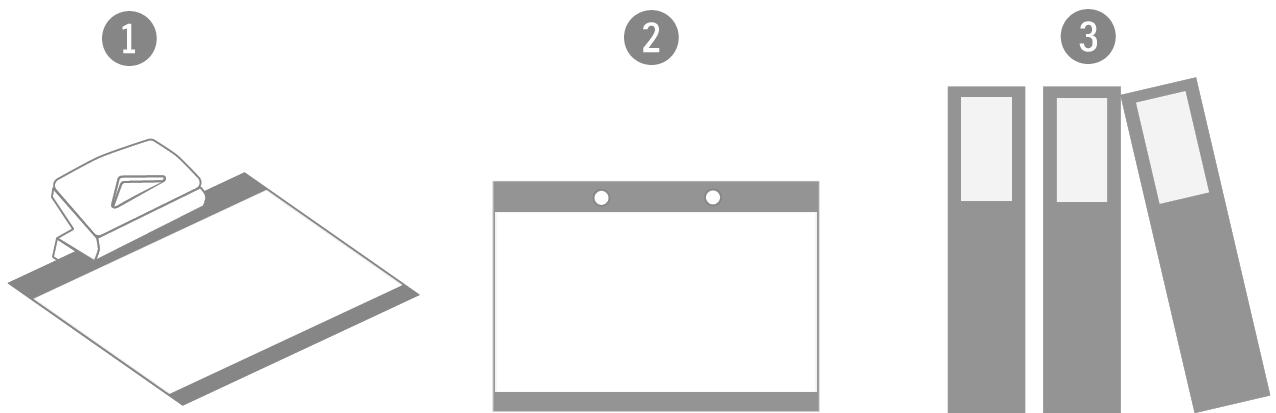
Lightware Visual Engineering supports green technologies and eco-friendly mentality. Thus, this document is made primarily for digital usage. If you need to print out a few pages for any reason, follow the recommended printing settings:
▪Page size: A4
▪Output size: Fit to page or Match page size
▪Orientation: Landscape
TIPS AND TRICKS: Thanks to the size of the original page, a border around the content (gray on the second picture below) makes it possible to organize the pages better. After punching holes in the printed pages, they can easily be placed into a ring folder.
LARA Disclaimer
Reliable sources
The software does not certify, authenticate, or track 3rd-party modifications of the modules that can be uploaded to LARA by users.
Confidential data storage and cloning
Modules have access to other modules’ data which might contain confidential information (eg. passwords and usernames) as well as its local files. The downloaded configurations and the user interface might also contain confidential information as plain text.
Cloning, backup authenticity
LARA allows users to save a backup of their configurations to external files. These downloaded backups can be modified without restrictions. LARA does not verify the authenticity of the backup when it is uploaded again.
Access management
LARA supports only one level of access: currently a single administrator user account is available. It has full access to all available data in the system. The administrative password should be kept confidential.
Self-signed certificates
Only self-signed certificates are supported for HTTPS connections. Certificates signed by CA’s cannot be used at the moment.
Permissions in the module
The modules are not limited in their access to networks. They have access to the internet, the local network, they can also forward data between the two.
Firewall
The modules in the software are within the firewall of the Taurus device, meaning that they can reach the LW3 protocol server without authentication.
TO THE MAXIMUM EXTENT PERMITTED BY APPLICABLE LAW, IN NO EVENT SHALL LIGHTWARE BE LIABLE TO THE USER OR LICENSEE FOR ANY DIRECT, SPECIAL, EXEMPLARY, CONSEQUENTIAL, INDIRECT, PUNITIVE, OR SIMILAR DAMAGES OR LOST PROFITS OR LOST DATA ARISING OUT OF THE USE OR INABILITY TO USE THE PRODUCT EVEN IF LIGHTWARE HAS BEEN ADVISED OF THE POSSIBILITY OF SUCH DAMAGES.
IN NO EVENT SHALL LIGHTWARE BE LIABLE FOR ANY DAMAGES CAUSED BY THE USAGE OF THE PRODUCT WHICH IS NOT IN ACCORDANCE WITH THE LARA DISCLAIMER.
IN NO EVENT SHALL LIGHTWARE BE LIABLE FOR ANY DAMAGES ARISING OUT OF ISSUES REVEALED IN THE LARA DISCLAIMER.
THE COMPANY, WHICH INSTALLS THIS SOFTWARE ON THE HARDWARE(S) OF THE USER UNDERTAKES THE OBLIGATION TO COLLECT A STATEMENT OF ACCEPTANCE OF THE ABOVE LIMITATIONS BY THE USER IN THE FORM REQUIRED BY THE LAW APPLICABLE TO THE USER AND THIS COMPANY UNDERTAKES TO INDEMNIFY LIGHTWARE FOR ALL DAMAGES – WHETHER SPECIAL, EXEMPLARY, CONSEQUENTIAL, INDIRECT, PUNITIVE, OR SIMILAR – ARISING OUT OF BREACHING ITS FOREGOING OBLIGATION.