![]()
User Manual
USB20-1GBE-DS4
USB20-1GBE-DS4P
USB20-1GBE-HS10
USB20-1GBE-HS13P
USB 2.0 Signal Extender
|
|
|
|
||
|
|
|
|
||
|
|
||||


|
|
|
|||
|
|
|
|


Class II apparatus construction.
The equipment should be operated only from the power source indicated on the product.
To disconnect the equipment safely from power, remove the power cord from the rear of the equipment or from the power source. The MAINS plug is used as the disconnect device, the disconnect device shall remain readily operable.
There are no user-serviceable parts inside of the unit. Removal of the cover will expose dangerous voltages. To avoid personal injury, do not remove the cover. Do not operate the unit without the cover installed.
The appliance must be safely connected to multimedia systems. Follow instructions described in this manual.
Ventilation
For the correct ventilation and to avoid overheating, ensure enough free space around the appliance. Do not cover the appliance, leave the ventilation holes free and never block or bypass the ventilators (if there are any).
WARNING
To prevent injury, the apparatus is recommended to be securely attached to the floor/wall, or mounted in accordance with the installation instructions. The apparatus shall not be exposed to dripping or splashing, and no objects filled with liquids, such as vases, shall be placed on the apparatus. No naked flame sources, such as lit candles, should be placed on the apparatus
Waste Electrical & Electronic Equipment (WEEE)

This marking shown on the product or its literature indicates that it should not be disposed with other household wastes at the end of its working life. To prevent possible harm to the environment or human health from uncontrolled waste disposal, please separate this from other types of wastes and recycle it responsibly to promote the sustainable reuse of material resources. Household users should contact either the retailer where they purchased this product or their local government office for details of where and how they can take this item for environmentally safe recycling. Business users should contact their supplier and check the terms and conditions of the purchase contract. This product should not be mixed with other commercial wastes for disposal.
Common Safety Symbols
|
Symbol |
Description |

|
Direct current |

|
Alternating current |
|
Protective conductor terminal |
|
Equipotential Connector |
.png)
|
On (Power) |
.png)
|
Off (Power) |

|
Double insulation |

|
Caution, possibility of eletric shock |

|
Caution |

|
Laser radiation |

|
Warning, Rotating fan |

|
Caution: for indoor use only |
Applied SW/FW/HW Environment
All presented functions refer to the indicated products. The descriptions have been made while testing these functions in accordance with the indicated Hardware/Firmware/Software environment:
|
Item |
Version |
|
Hardware version |
v1.0 |
Document Revision History
|
Rev. |
Release date |
Changes |
Editor |
|
1.0 |
2024-04-24 |
Initial document |
Nikolett Keindl |
|
... |
|||
|
v3 |
2025-12-01 |
Minor corrections |
Laszlo Zsedenyi |
|
v4 |
2026-03-04 |
Default mode info added |
Laszlo Zsedenyi |
Contact Us
+36 1 255 3800
+36 1 255 3810
Lightware Visual Engineering PLC.
Gizella 51-57, Budapest H-1143, Hungary
©2026 Lightware Visual Engineering. All rights reserved.
All trademarks mentioned are the property of their respective owners.
Specifications are subject to change without notice.
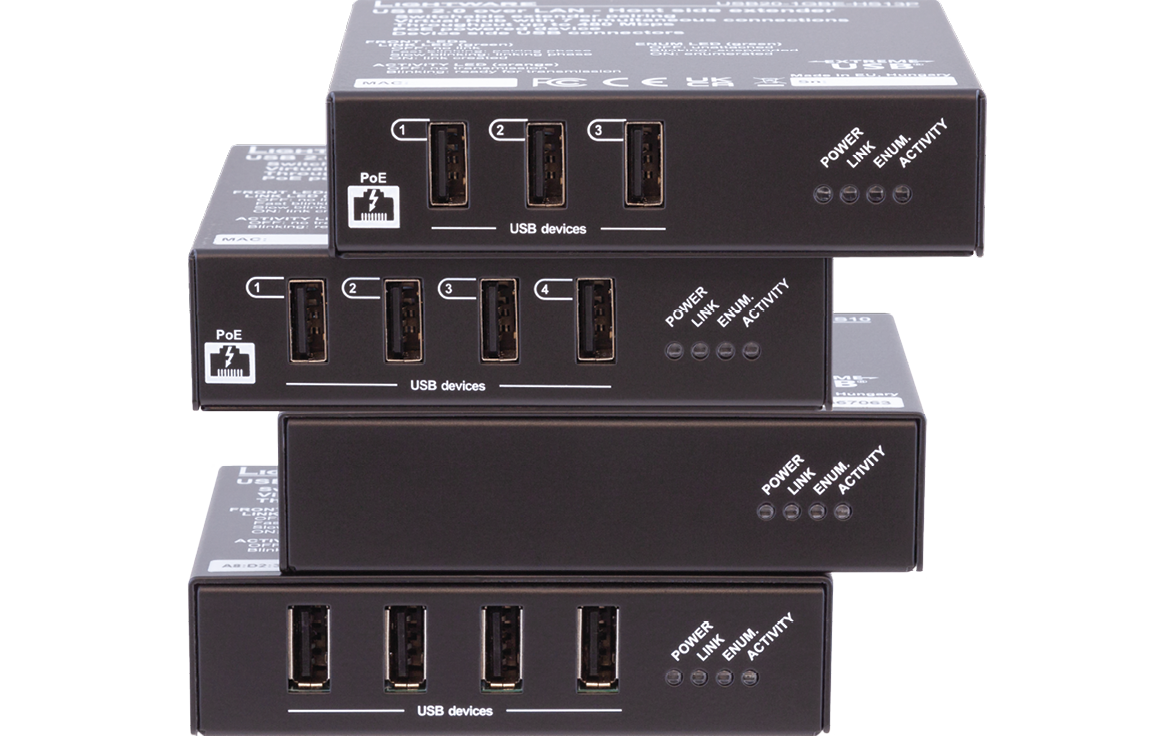
Thank You for choosing Lightware’s USB20 Extender series device. In the first chapter we would like to introduce the device, highlighting the most important features in the sections listed below:
1.1. Description
The USB20 Extender series can be used to build a system to transmit USB signals across greater distances than what is generally allowed by a USB cable, taking advantage of the data transmission capabilities of CATx cables and network switches. By using switches, transmission distances of up to 100 meters can be reached. This makes it possible to place USB devices (such as microphone, webcamera, keyboard and mouse, mass storage etc.) far away from the Host device while still having full usage of them.
Model Denomination
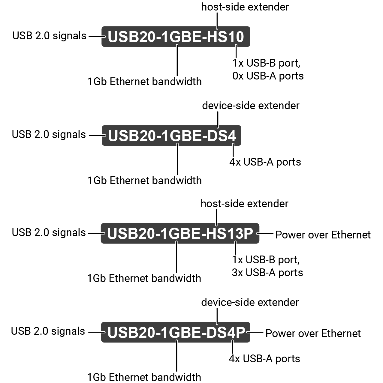
About the Serial Number
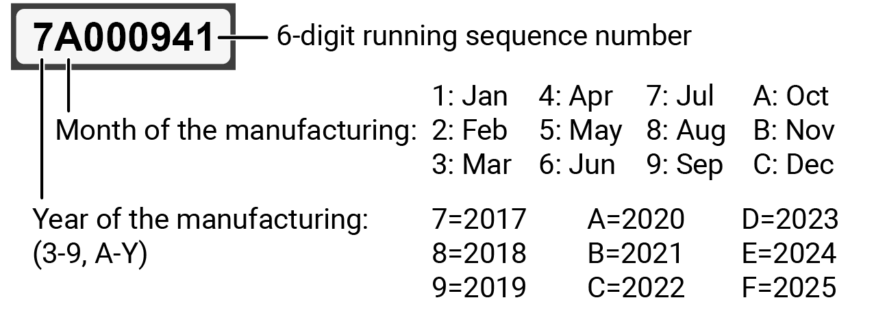
Lightware devices contain a label indicating the unique serial number of the product. The structure is the following:
From 1st of October 2024, serial number format of Lightware devices is the following: the first two digits are of the year of manufacture, while the remaining digits make up the running sequence number.

|
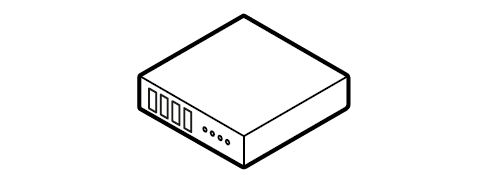
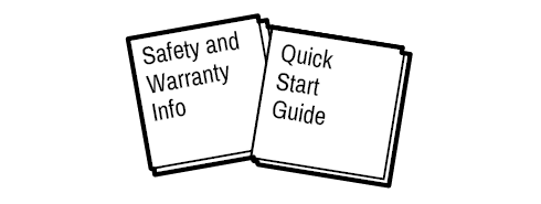
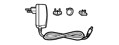
Supplied accessories |
|||
|
|
|
|
|
Extender device |
Safety & warranty info, Quick Start Guide |
24V DC adaptor with interchangeable plugs |
|
|
USB20-1GBE-DS4 |
|
|
|
|
USB20-1GBE-DS4P |
|
|
- |
|
USB20-1GBE-HS10 |
|
|
|
|
USB20-1GBE-HS13P |
|
|
- |


|
Remote Power (PoE+) |
|
The devices can be Powered over Ethernet (according to IEEE 802.3at) by a compatible power source equipment. |
|

|
USB Extension |
|
KVM extension for USB HID (Human Interface Devices, e.g. keyboard, mouse, webcamera, presenter) and Mass Storage devices (Flash drive, Hard drive). |
|

|
USB20 Configurator Software |
|
The extenders can be controlled with the 'USB20 1Gbe Configurator' software tool that can be used to connect other Icron-based USB devices, too. #new |
1.4. Typical Application
Connecting the extenders directly
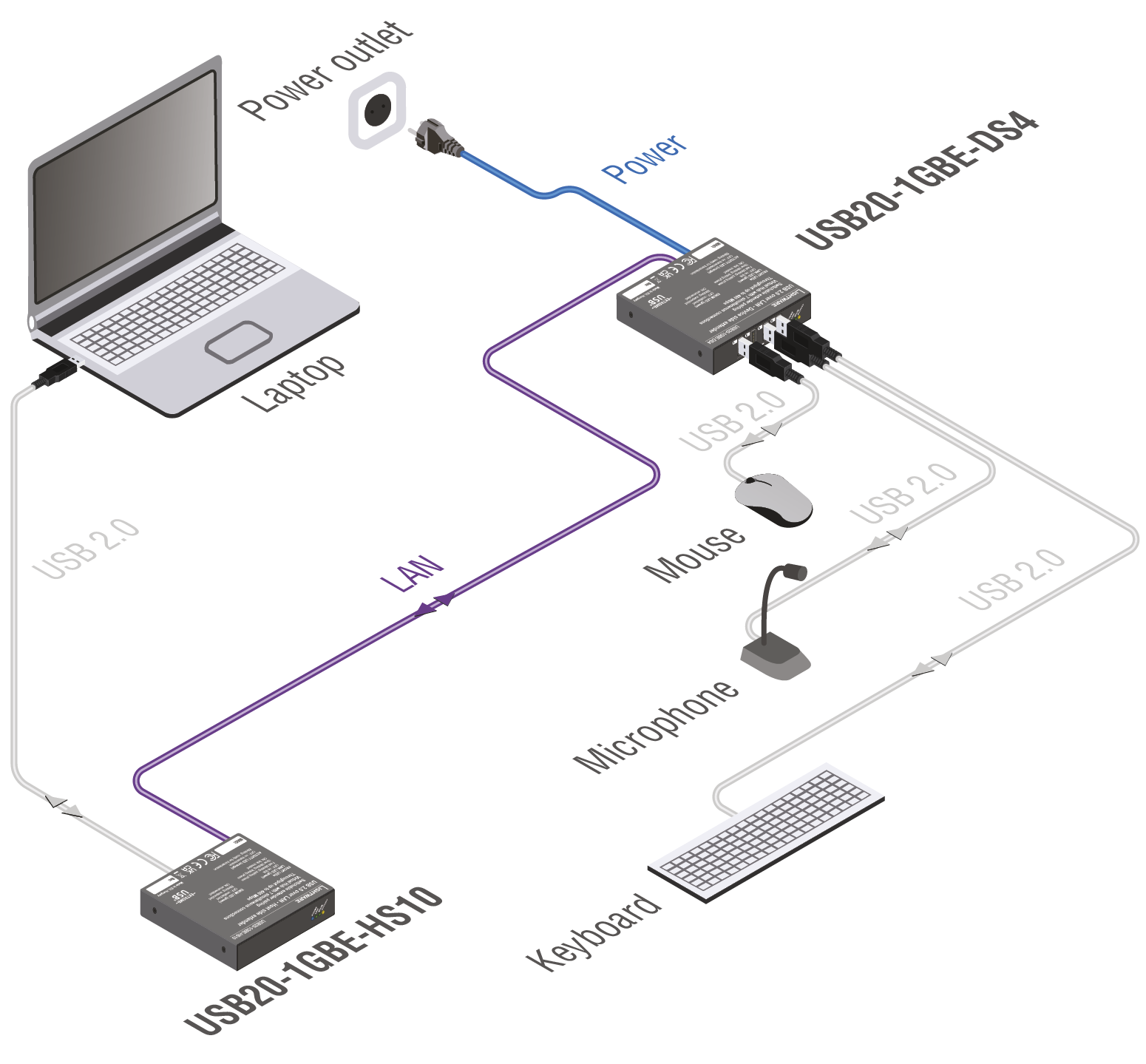
Creating a system by connecting the extenders directly
Connecting the extenders using a switch
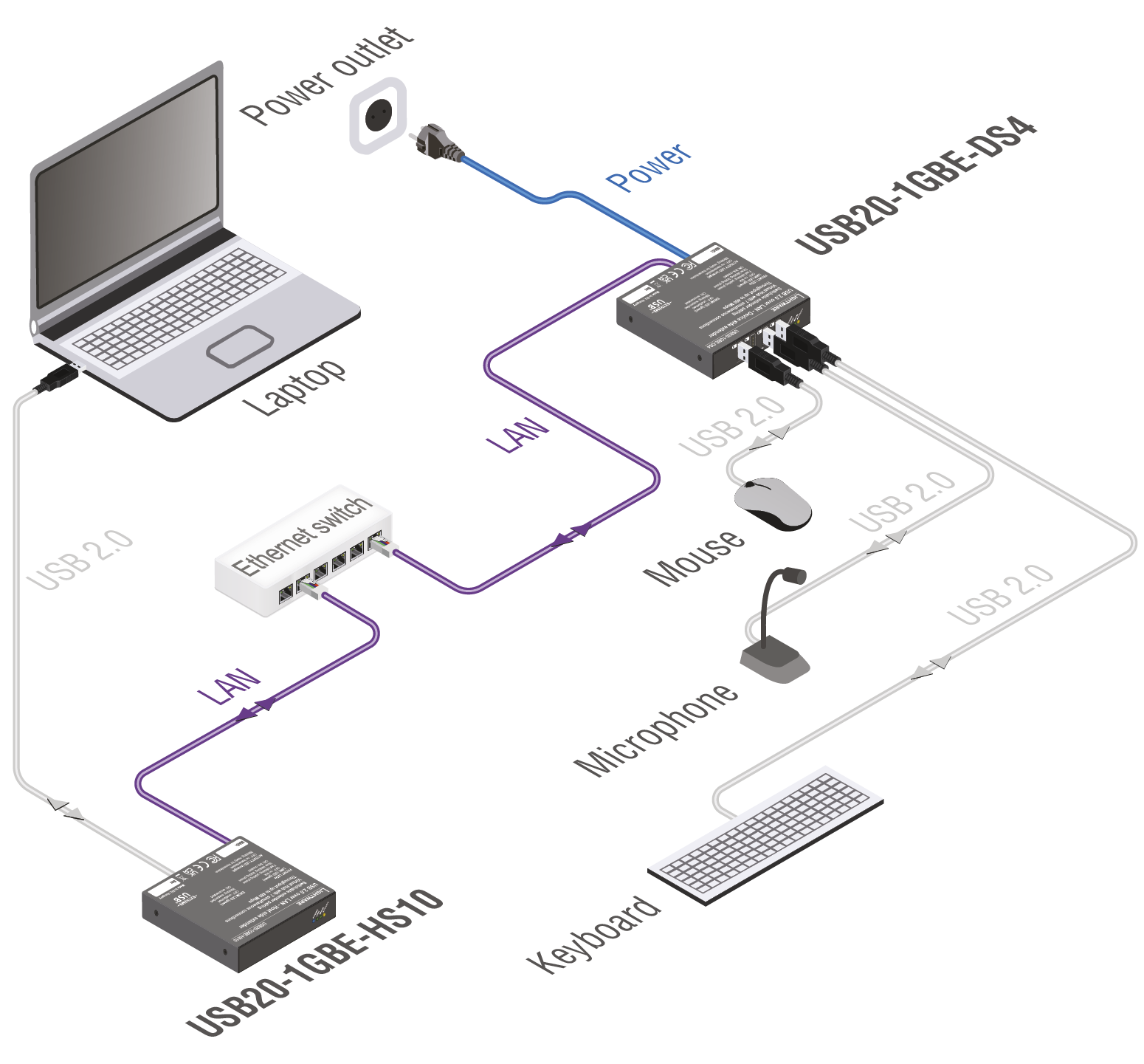
Creating a system using an Ethernet switch
Connecting the extenders using a PoE+ switch

Creating a system using a PoE+ capable Ethernet switch
The following sections are about the physical structure of the device, input / output ports, LEDs and connectors:
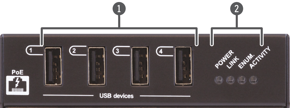
USB20-1GBE-DS4
USB20-1GBE-DS4P
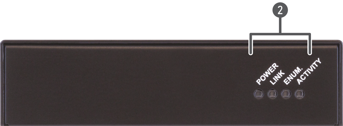
USB20-1GBE-HS10
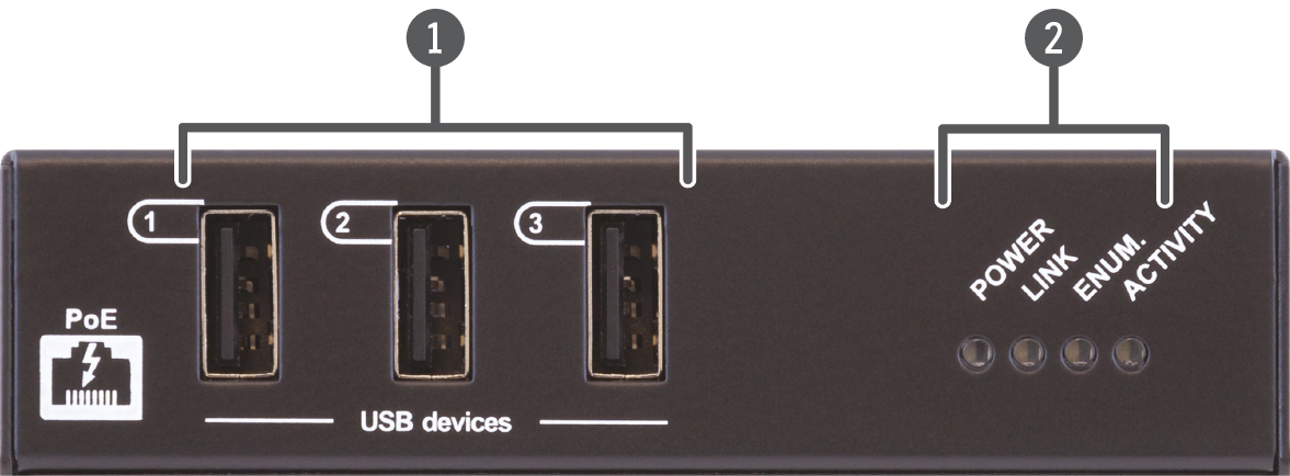
USB20-1GBE-HS13P
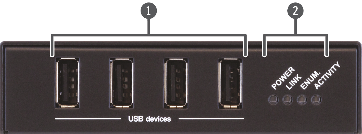
|
|
USB-A Ports |
USB A-type connectors for USB devices. |
|
|
Status LEDs |
See the details in the Front Panel LEDs section. |


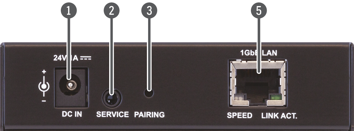
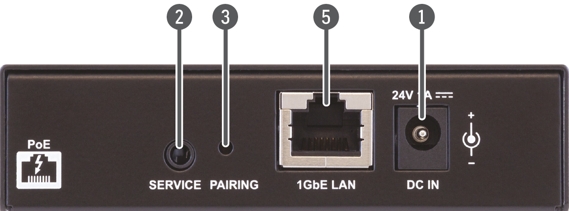
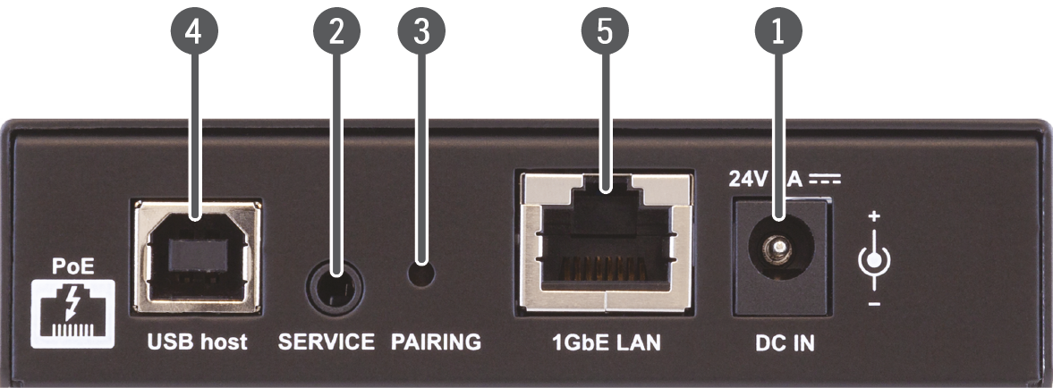
2.2. Rear view
USB20-1GBE-DS4
USB20-1GBE-DS4P
USB20-1GBE-HS10
USB20-1GBE-HS13P
|
|
DC Power Connector |
24V DC connector for powering the device. |
|
|
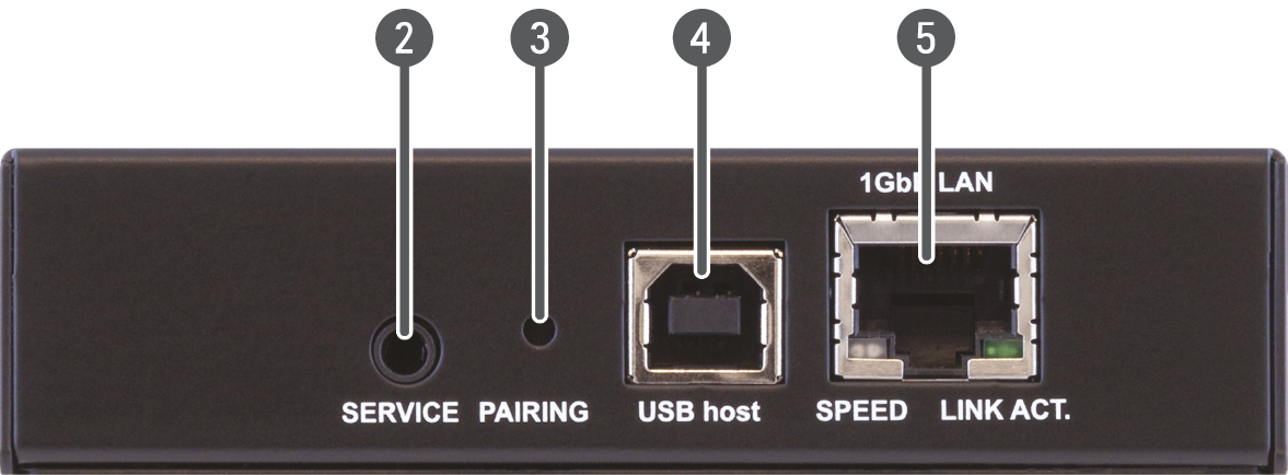
Service Port |
Port for service purposes. |
|
|
Pairing Button |
Button for pairing the extenders. For details, see the Button Functionality section. |
|
|
USB-B Port |
USB B-type port for connection to the host device. |
|
|
RJ45 Connector |
RJ45 connector for Ethernet connection. |


|
Power LED |
||||

|
off |
The device is not powered, or PoE source is not detected.. |
||

|
red |
on |
The device is powered by PoE, but power is insufficient. |
|

|
blue |
on |
The device is powered on. |
|
DIFFERENCE:PoE-dependent functions are only present in models USB20-1GBE-HS13P and USB20-1GBE-DS4P.
|
Link LED |
||||
|
|
off |
The device is not paired yet. |
||

|
green |
blinking slow |
The linking process has started. |
|

|
green |
blinking fast |
The pairing process has started. |
|

|
green |
on |
The pairing process has finished, link is created. |
|
|
Enumeration LED |
||||
|
|
off |
Extender is not enumerated by the host. |
||
|
|
green |
blinking |
Extender enumeration is suspended. |
|

|
green |
on |
Extender enumeration is completed. |
|
|
Activity LED |
||||
|
|
off |
There is no transmission. |
||

|
yellow |
blinking |
The extender is ready for transmission. |
|
RJ45 LEDs (USB20-1GBE-HS10 and USB20-1GBE-DS4 models)
|
Speed LED |
||||

|
off |
There is no Ethernet connection. |
||

|
green |
on |
The connection bandwidth is 1000 Mbps. |
|

|
yellow |
on |
The connection bandwidth is 10/100 Mbps. |
|
|
Link Activity LED |
||||
|
|
off |
There is no Ethernet connection. |
||

|
green |
blinking occasionally |
Extender is not paired. |
|

|
green |
blinking repeatedly |
Host side extender is attempting to pair. |
|

|
green |
blinking quickly |
Extender is paired.. |
|
The extender devices have a Pairing button on the rear side. This button has several functionalities as seen below. #pairing
Pairing happens using the MAC address of the devices. It does not happen automatically, it must be done manually. The process is the following:
Step 1.Use a long, thin object (e.g. a paper clip) to press the Pairing button of one of the devices once shortly. This will cause the Link LED to flash quickly.
Step 2.Press the Pairing button on the other device in the same way. The Link LED of both devices will light continuously, and the MAC address of the device-side extender is added to the list of paired devices in the host-side extender and vice versa.
Step 3.Repeat the procedure for each device-side extender in the system. Up to seven device-side extenders can be paired with a single host-side extender at once.
The pairing procedure has a time limit of 10 minutes. If the pairing does not occur in this timeframe, the procedure must be restarted.
Paired devices will remain that way even if the devices are turned off or restarted.
INFO:If the devices are paired, but there is no network connection, the Link LED will blink slowly.
2.4.2. Deleting a Paired Device
You can delete paired devices from the memory by pressing the Pairing button for more than 10 seconds. Please keep in mind that this will only delete the pairing list in the current device. To completely remove the pairing in both devices, this procedure must be done on both of them.
2.4.3. Setting a Dynamic IP Address
You can set DHCP by pressing the Pairing button for the first 5 seconds of the device turning on. DHCP gets enabled and the device restarts. #dhcp
ATTENTION!Make sure you have a DHCP server in the network. If the extender is installed in a network without a DHCP server, the device will be unreachable even with the USB20 configurator software.
This chapter is about the installation of the device and connecting to other appliances, while also presenting the mounting options, the electrical connections and further assembly steps:
To mount the extenders, Lightware supplies optional accessories for different usage. There are two kinds of mounting kits with similar fixing methods. The extenders have two mounting holes with inner thread on the bottom side; see the bottom view in the Mechanical drawings section. To order mounting accessories, please contact sales@lightware.com. Fasten the devices with the screws enclosed to the accessory.
For further mounting information, please see the Mounting Assembly Guide.
WARNING!Always use the supplied screws. Using different (e.g. longer) ones may cause damage to the device.
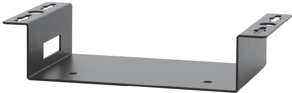
3.1.1. 1U High Rack Shelf
Allows rack mounting for half-rack, quarter-rack and pocket sized units.
INFO:The USB20 Extender series devices are quarter-rack sized.
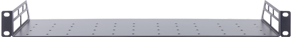
1U hish rack shelf provides mounting holes for fastening two half-rack or four quarter-rack sized units. Pocket sized devices can also be fastened to the shelf.
Mounting steps
Step 1.Unplug all the cables connected to the device(s).
Step 2.Turn the device(s) upside down.
Step 3.Put the shelf upside down on the device(s). Position it to get the mounting holes aligned.
Step 4.Fasten the device to the shelf with the provided screws.
Step 5.Fix the shelves to the desired place (screws are not supplied).
3.1.2. Under Desk Mounting Kit (UD-kit)
The UD-kit makes it easy to mount one extender under any flat surface (e.g. furniture).
The mounting steps are the same as they are with the rack shelf.
3.1.3. UD Mounting Kit Double (UD-kit double)
The UD-kit double makes it easy to mount two extenders under any flat surface (e.g. furniture).
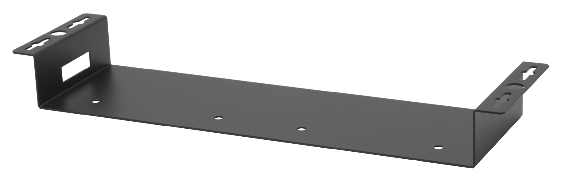
The mounting steps are the same as they are with the rack shelf.
USB Type-A

USB Type-A connectors for USB devices.
These ports are capable of supplying 1A to the connected USB devices, up to a maximum of 3A across all four ports.*
* USB20-1GBE-HS13P only has 3 USB Type-A ports.
USB Type-B
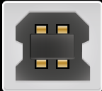
USB Type-B port for connection to a USB host device.
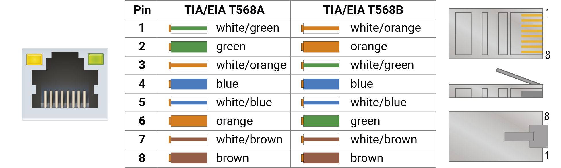
1 GbE LAN
The devices provide standard RJ45 connectors for Ethernet connection
The powering of the devices can happen in the following ways:
Local Powering
USB20-1GBE-DS4, USB20-1GBE-DS4P and USB20-1GBE-HS13P can all be powered by a DC power adaptor.
INFO:Power adaptor is only supplied with USB20-1GBE-DS4. For the other models please contact sales@lightware.com.
Powering over USB
The USB20-1GBE-HS10 model is powered by the host computer over the USB cable.
Power over Ethernet
USB20-1GBE-DS4 P and USB20-1GBE-HS13P models are able to be powered by a PoE+ capable switch or a PoE+ power injector.
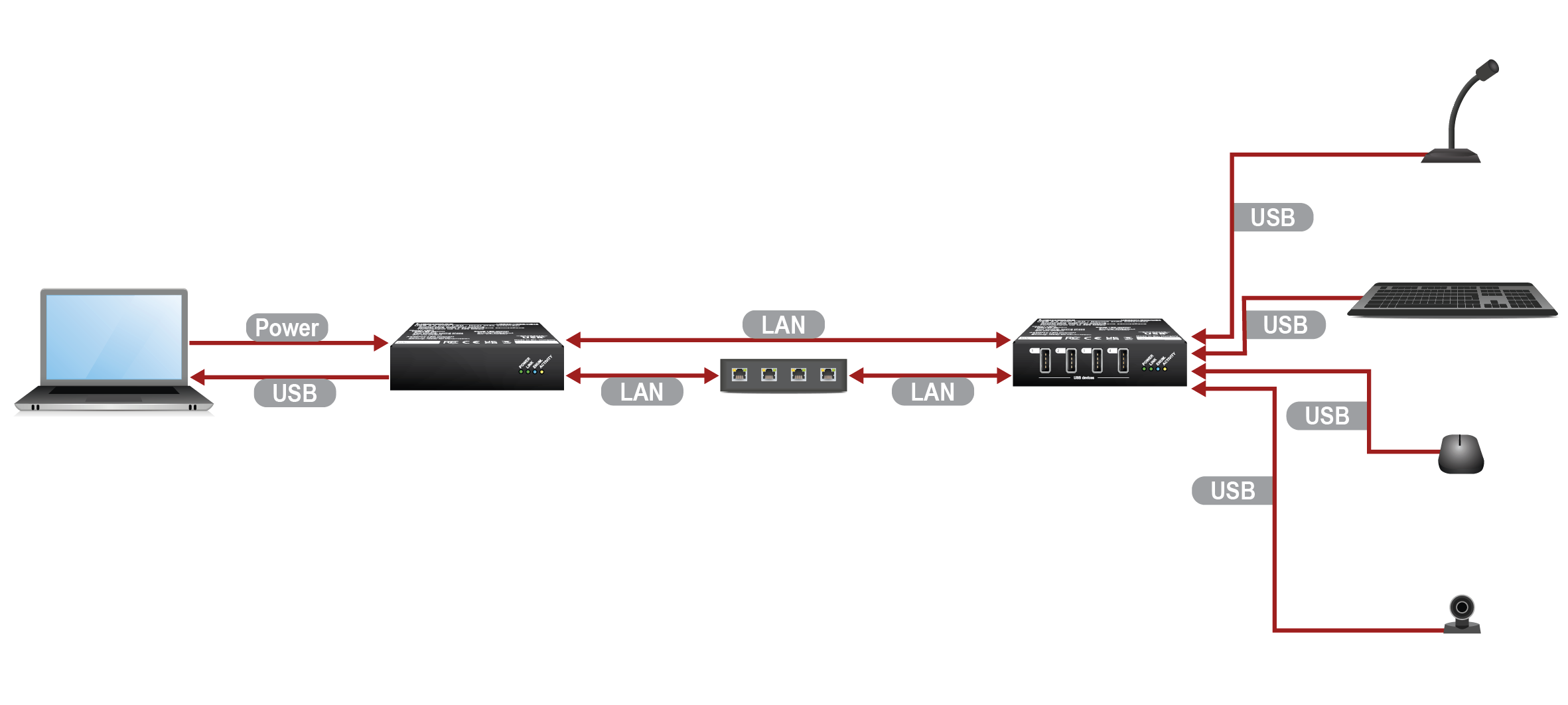
|
|
Connect the host device to the USB20-1GBE-HS10 device with a USB cable through the USB B-type connector. |
|
|
The host provides power to the USB20-1GBE-HS10 device via the USB cable. |
|
|
Connect the USB20-1GBE-HS10 and USB20-1GBE-DS4 devices with CATx cables. Optionally you can insert an Ethernet switch between the extenders for additional extension distances. |
|
|
Connect the USB devices to the USB20-1GBE-DS4 device with USB cables through tha USB A-type connectors. |
ATTENTION!Make sure you have a DHCP server in the network. If the extender is installed in a network without a DHCP server, the device will be unreachable even with the USB20 configurator software.
The devices can be controlled by a computer or an external controller via Ethernet with the USB20 Configurator software. It can be installed on a computer with Windows OS. The application can be downloaded from www.lightware.com.
Minimum System Requirement
▪RAM: 2 GB
▪Minimum display resolution: 1600x900
ATTENTION!Please make sure that SDVoE Server is not running on the network that controls the desired Lightware devices.
How to Stop Other Blueriver Server Applications?
If a BlueRiver server is running on a PC, and it's connected to the AV network beside the Configurator, it causes two servers presence on the network which would result malfunction in the devices.
Solution
The BlueRiver server shall be stopped in the PC by terminating it down in the Windows Task Manager.
Step 1.Launch the Task Manager in the Windows operating system.
Step 2.Navigate to the Services menu.
Step 3.Search these two services:
=bavm - BlueRiver AV Manager Service
=bavm_sdvoe_api - BlueRiver AV Manager SDVoE API Service
Step 4.Select both lines and click on the  Stop button to terminate them.
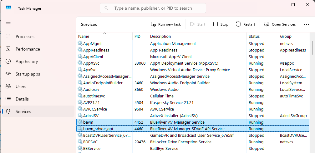
BlueRiver AV Manager services are running under Windows
LW Device Compatibility
The software is compatible with the following Lightware devices with Icron USB module:
▪USB20-1GBE series
▪HDMI-TPN devices with Icron USB extension
▪UCX-TPN devices with Icron USB extension
▪UBEX-PRO20-HDMI-F130
4.2. The Discovery Page
This page shows the devices discovered on the network. You can select and configure the devices that will be handled via the Crosspoint page.
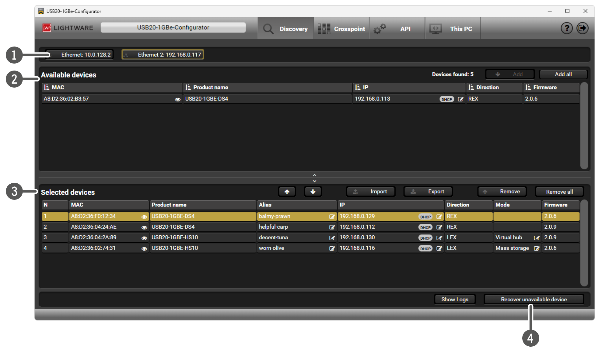
The Discovery Page
|
|
Network Interfaces |
The Network Interface Cards (NIC) of the PC are shown. You can select the interface where the devices to be discovered. |
|
|
The discovered devices are in this list. It is updated automatically, refresh is not necessary. More details can be found in the Available Devices section. |
|
|
|
Selected Devices |
The desired devices can be selected from the upper list; the selected devices will disappear from there. |
|
|
Recover unavailable device |
The IP settings can be changed for a device based on the MAC address. This will help recover devices with wrong settings. |
ATTENTION!When a red triangle  is displayed, the network interface cannot be used, most likely that the UDP 6137 port is not available. This might be caused by running another software using the same port (e.g. an SDVoE server). Please close the other software as desribed in First Steps section.
ATTENTION!You have to run the software with Administrator privileges to store the settings.
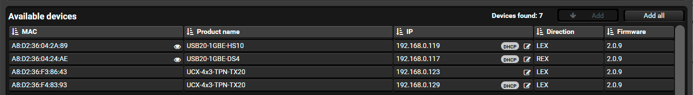
The following columns can be seen:
|
Field |
Function |
|
MAC |
The MAC address of the devices that is printed on the device top phisically. When clicking on the |
|
Product name |
Coming from the device. |
|
IP |
The IP address of the device. It can be changed by clicking on the |
|
Direction |
Local Extender (LEX) or Remote Extender (REX). |
|
Firmware |
The actual version. |

Select the desired devices (hold the SHIFT button pressed to select more) and press the Add button.
ATTENTION!Make sure you have a DHCP server in the network. If the extender is installed in a network without a DHCP server, the device will be unreachable even with the USB20 configurator software.
4.2.2. Selected Devices
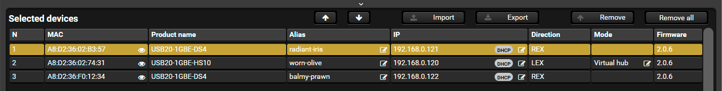
The following columns are displayed:
|
Field |
Function |
|
N (ID number) |
Automatically assigned number. The devices are always ordered by number, counting from one. It can be modified by selecting one (or more) item(s) and using the |
|
MAC |
The MAC address of the device that is printed on the device top phisically. When clicking on the |
|
Product name |
Coming from the device. |
|
Alias |
When adding a device to the list, an easy-to-remember name is created, automatically, based on the MAC address. Thus, the same device will get the same auto alias every time, but it can be changed by clicking the |
|
IP |
The IP address of the device. It can be changed by clicking on the |
|
Direction |
Local Extender (LEX) or Remote Extender (REX). See more details in the Direction Setting section. |
|
Mode |
Available only for LEX devices. See more details in the Mode Setting of LEX Devices section. |
|
Firmware |
The actual version. |


ATTENTION!This list is saved automatically, but you have to run the software with Administrator privileges to store the settings.
When a device is not available on the network (eg. turned off or removed, or never found after starting the software), it will be displayed in grey and a red triangle is displayed.
Control Buttons
|
|
Changing the order of the selected devices. The order will determine how the devices are taken to the crosspoint. |
|
|
A previously saved JSON file can be opened; all current settings will be overwritten. |
|
|
All settings can be saved into an editable JSON file. |
|
|
Yellow-highlighted devices will be moved from the Selected devices list to the Available devices list. (Use the Shift button to highlight more devices.) |
|
|
The Selected devices list will be emptied. |


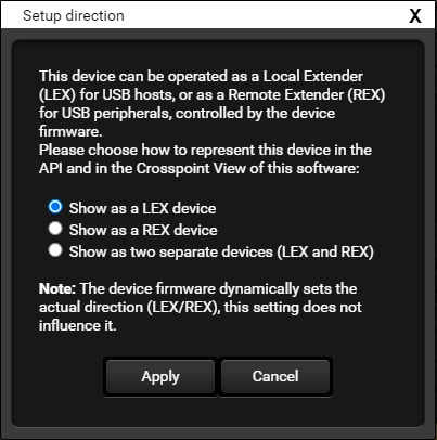
The signal direction of the Icron can be changed in certain devices. In this case, a  symbol is displayed in the Direction column. The Icron device can be operated as a Local Extender (LEX) for USB hosts, or as a Remote Extender (REX) for USB peripherals.
Important notes:
▪This does not change anything in the device. A change can be triggered only in the device itself.
▪When BiDirectional (BiDi) setting is valid in the device, the crosspoint will show two devices, a LEX and a REX (only one is active at a time).
▪When REX is selected for a device in this window, but operation mode is LEX, or vice versa, an notice will be displayed.
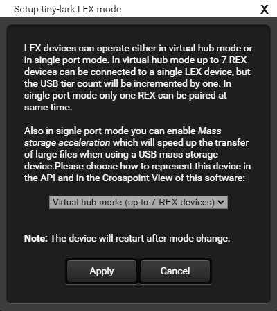
The LEX device can be used as follows:
|
Mode |
Function |
|
Single port mode with MSA disabled |
One REX can be connected to the LEX. |
|
Single port mode with MSA enabled |
One REX can be connected to the LEX. This option will speed up the transfer of large files using a USB mass storage device. |
|
Virtual hub mode (default) |
Up to 7 REX devices can be connected to the desired LEX device, but in this case the USB tier count will be incremented by one. |
When configured mode and actual mode doesn't match, a yellow triangle will be displayed.
Single port mode means that the USB devices will be arranged to separate USB tiers; see the example below.
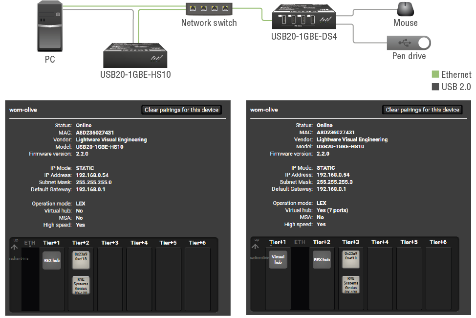
Comparing Single port and Virtual hub modes – at the same layout
Connected REX Device Data Storing
LEX device stores the previously connected REX device data and restores when changing the mode back again. E.g. if the mode is changed from Virtual hub to Single port mode, one REX connection remains active: the oldest connected one. If the mode is changed back to Virtual hub again, the previous REX connections will be restored.
ATTENTION!You have to run the software with Administrator privileges to store the settings.
The device is restarted automatically after changing the mode.
4.3. The Crosspoint Page
This tab can be opened only if at least one device is added to the Selected devices list.
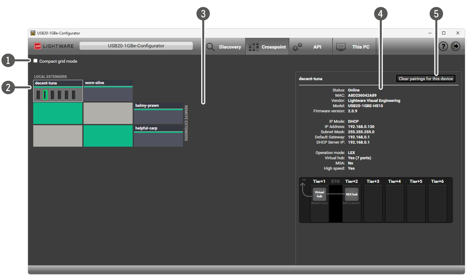
The Crosspoint Page in Full Grid View
|
|
Layout selector |
Compact grid view and Full grid view can be switched by the selector. |
|
|
LEX devices |
|
|
|
REX devices |
|
|
|
Extender panel |
Basic information is displayed about the extender. The USB topology is shown for LEX devices if USB host is present, however, only the added tiers can be seen. Showing the "upwards" over the LEX device first hub is not possible. Further info is displayed as a tooltip. |
|
|
Clear pairings for this device |
Terminates all connections between the highlighted LEX and the paired REX devices. It is also useful when a connection to an extender got stuck for some reason. |

When there are connection issues between two linked devices, the grid icon will be red.
Extender Tiles
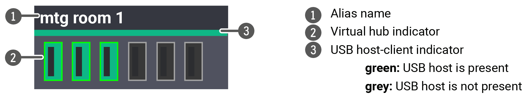
Device Status Indicators
|
|
The device is available and connected to another extender. |
|
|
The device is available but not connected to another extender. |
|
|
The device is not available. |


Virtual Hub Indicator (only for LEX devices)
|
|
The port is used and operational. |
|
|
The port is not used. |
|
|
The port is paired to a REX but the connection is not established. |


Compact Grid Mode
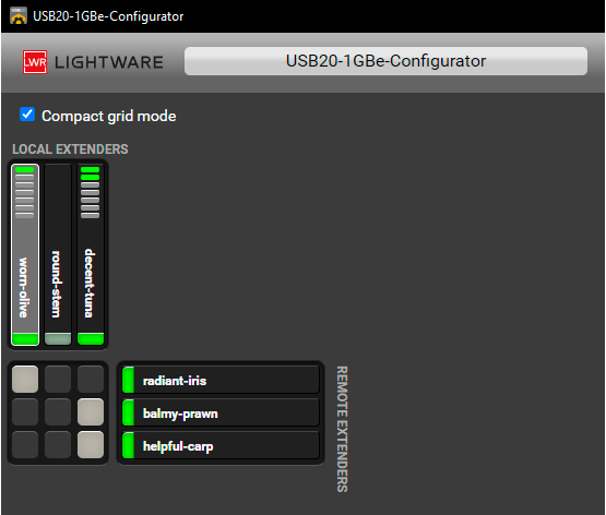
The layout can be switched to Compact grid mode which has the same functionality as the Full grid mode. It is useful when more devices are in the crosspoint.
4.4. The API Page
This page is for introducing and setting the control options with the API. This API allows sending commands to the devices from the same/another computer or from an external controller device. A typical example is when a Touch panel (tablet) is in a meeting room, and pressing the button on the screen will send command to the devices (via the computer running the API).
DIFFERENCE:The API allows the controlling functions that are available on the Crosspoint page. The API cannot be used for setting the network properties (IP address, direction, mode settings, etc...).
This page contains three sections:
▪Settings
▪Tester
▪Log
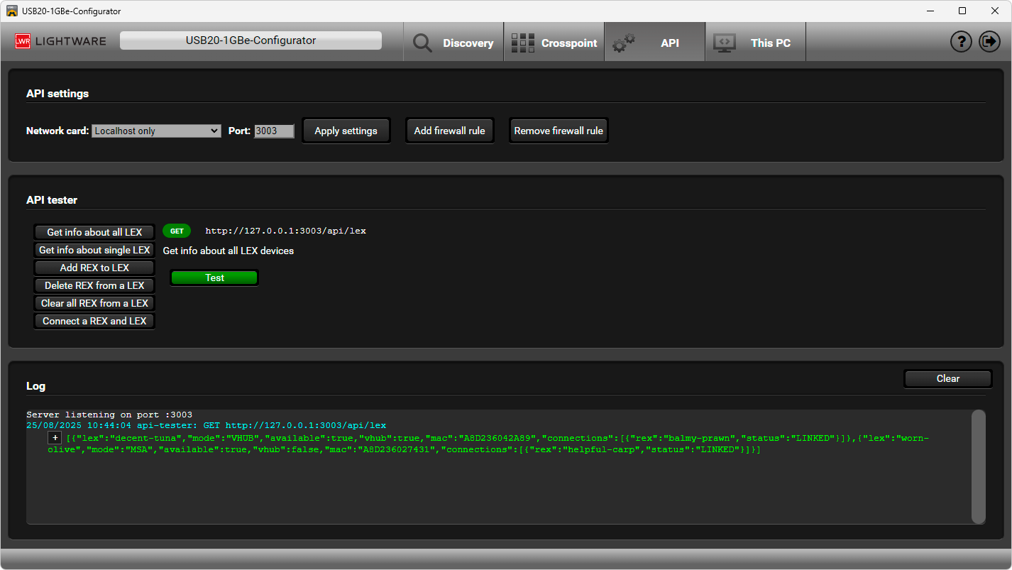
The API Page
API Settings
In this section, you can set the NIC where the API server to run, but only one. You can add or remove an exception (firewall rule); a window will pop up about the change.
4.4.1. API Commands and Tester
Six buttons can be used for executing the available REST API commands. When selecting one, more details appear. Press the Test button, to execute the query (even when API server is not available), the result can be checked in the Log section. The last 1000 commands are displayed only due to performance reasons. By clicking on the + sign before the response, the log content is shown in JSON format.
Get Info About a Single LEX Device
The response for this command contains the following information – in JSON format:
▪LEX local alias
▪Actual mode
▪MAC address
▪Actual REX connections (REX local alias, link status)
Request and Response
»request-line: GET·http://<ip:port>/api/lex/<local_alias>
«status-line: 200•OK
«body: <LEX_device_info>
Example
»request-line: GET http://192.168.0.11:3003/api/lex/worn-olive
«status-line: 200 OK
«body: {"lex":"worn-olive","mode":"VHUB","available":true,"vhub":true,"mac":"A8D236027431","connections":[{"rex":"radiant-iris","status":"LINKED"}]}
Get Information About All LEX Devices
The same information is in the response as above, but for all LEX devices (Discovery page: Selected devices).
Request and Response
»request-line: GET·http://<ip:port>/api/lex/<local_alias>
«status-line: 200•OK
«body: <LEX_device_info>
Example
»request-line: GET http://192.168.0.11:3003/api/lex/worn-olive
«status-line: 200 OK
«body: [{"lex":"worn-olive","mode":"VHUB","available":true,"vhub":true,"mac":"A8D236027431","connections":[{"rex":"radiant-iris","status":"LINKED"}]},{"lex":"tiny-lark","mode":"VHUB","available":true,"vhub":true,"mac":"A8D23602841D","connections":[]},{"lex":"mystic-hazelnut","mode":"MSA","available":true,"vhub":false,"mac":"A8D236F38643","connections":[]}]
Adding a REX Device to a LEX Device
This command creates a new connection. If the REX device is already connected to a LEX device, or the LEX has no free slot, the command will not be executed.
Request and Response
»request-line: POST·http://<ip:port>/api/lex/<LEX_local_alias>/add
»body: {"rex":"<REX_local_alias>"}
«status-line: 200•OK
«body: {"result":"ok"}
Example 1
»request-line: POST http://192.168.0.11:3003/api/lex/worn-olive/add
»body: {"rex":"radiant-iris"}
«status-line: 200 OK
«body: {"result":"ok"}
Example 2
»request-line: POST http://192.168.0.11:3003/api/lex/worn-olive/add
»body: {"rex":"radiant-iris"}
«status-line: 400 Bad Request
«body: {"result":"error","error":"LEX is already connected. Remove a REX first!"}
Connecting/Pairing a REX Device to a LEX Device
Force connecting a REX device to a LEX device. IF the LEX device is in Virtual hub mode without a free slot or it is in Single port mode connected to another REX device, the actual connections will be terminated. The new REX device will be connected to the LEX device.
Request and Response
»request-line: POST·http://<ip:port>/api/lex/<LEX_local_alias>/connect
»body: {"rex":"<REX_local_alias>"}
«status-line: 200•OK
«body: {"result":"ok"}
Example
»request-line: POST http://192.168.0.11:3003/api/lex/worn-olive/connect
»body: {"rex":"radiant-iris"}
«status-line: 200 OK
«body: {"result":"ok"}
Removing a REX Device from a LEX Device
Request and Response
»request-line: POST·http://<ip:port>/api/lex/<LEX_local_alias>/del
»body: {"rex":"<REX_local_alias>"}
«status-line: 200•OK
«body: {"result":"ok"}
Example
»request-line: POST http://192.168.0.11:3003/api/lex/worn-olive/del
»body: {"rex":"radiant-iris"}
«status-line: 200 OK
«body: {"result":"ok"}
Removing all REX Devices from a LEX Device
Request and Response
»request-line: POST·http://<ip:port>/api/lex/<LEX_local_alias>/clear
«status-line: 200•OK
«body: {"result":"ok"}
Example
»request-line: POST http://192.168.0.11:3003/api/lex/worn-olive/clear
«status-line: 200 OK
«body: {"result":"ok"}
4.5. USB Tiers ('This PC' Page)
This page shows the USB devices attached to the computer on the left side, the info panel is on the right side.
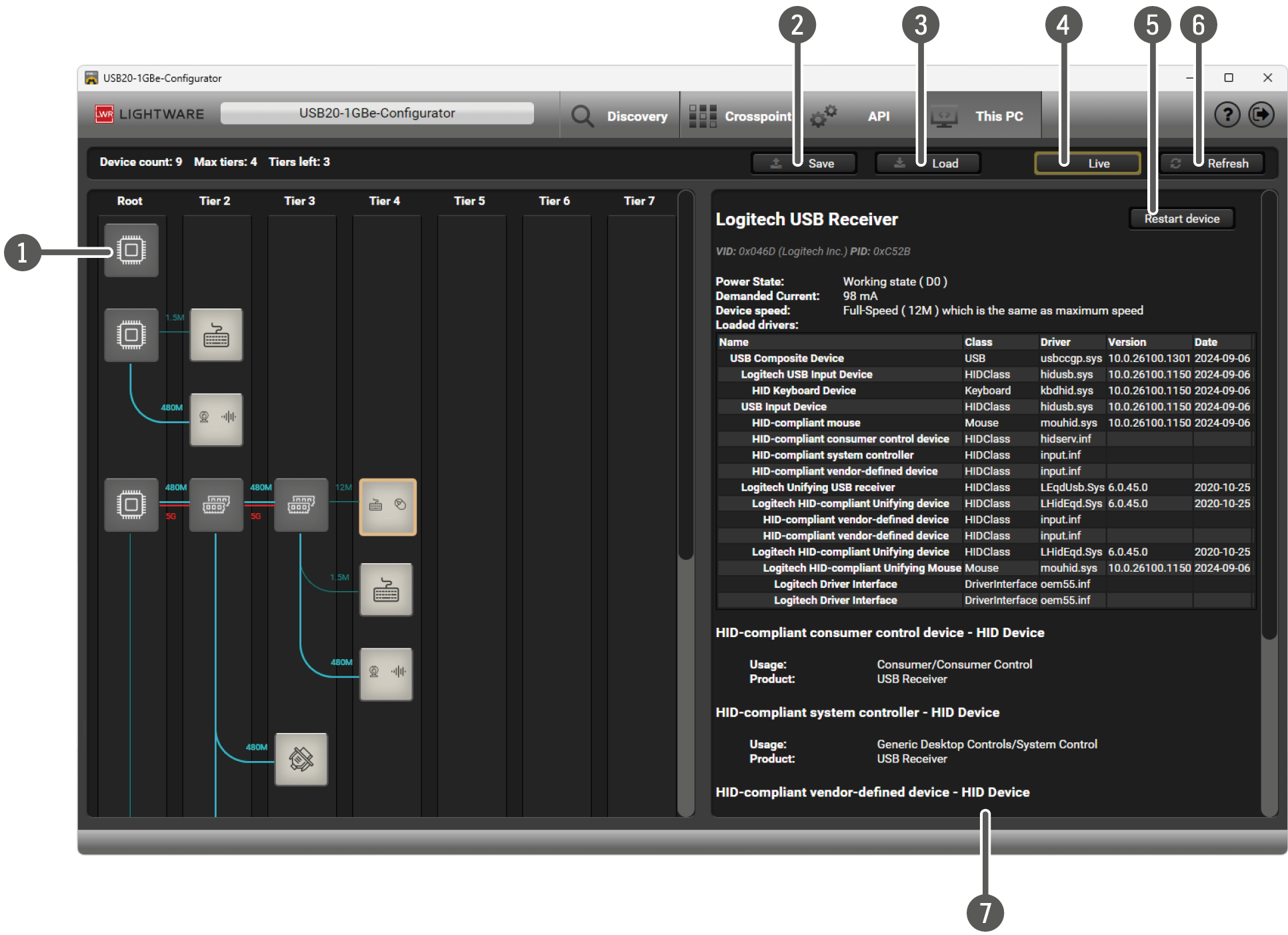
|
|
USB Device |
For more details about the icons see below. |
|
|
Save |
The actual state can be exported (e.g. sending to Lightware Support to analyze). |
|
|
Load |
The previous state can be imported. Please note that Live mode has been disabled after loading a state. |
|
|
Live button |
If the button is highlighted, the USB topology (left side) is updated automatically when changes happen (USB device is attached or removed). |
|
|
Restart Device |
This button will restart the selected USB device (after requesting administrator privilages if needed). |
|
|
Refresh |
Forcing a manual page content update. |
|
|
Info panel |
For more details about the Info panel content see the Important Notes below. Show UsbTreeview Information button: the original unparsed usbtreeview data is displayed. |


Important Notes
▪The root hub is in computers usually, but it can be in an external device, e.g. in a Thunderbolt adaptor.
▪First tier means the root hub. Tier 7 can only contain devices, hubs are not allowed in tier 7.
▪Attaching or removing empty USB hubs will not trigger a refresh.
▪Loading, updating or uninstalling a driver will not trigger a refresh, so the info panel may show outdated content.
▪USB companion hubs: when two hubs are detected as a companion hub (e.g. there is a USB2 and a USB3 hub in the same device), they are collapsed into a single hub and both superspeed and high speed connections are drawn. Exception: if these hubs have different parents or they are in a different tier, they are visualized separately.
USB Device Icons

|
USB hub |

|
USB device |
The symbol in the icon represents the USB device. In case of composite devices, up to four symbols are embedded in the icon. Question mark means special USB device (e.g. a USB programming cable).
The device can be controlled by a computer via UDP commands.
5.1. Instructions for the Terminal Application Usage
Terminal Application
The UDP protocol commands can be applied to the extenders using a terminal application. You need to install one of them on your control device, for example YAT. #terminal
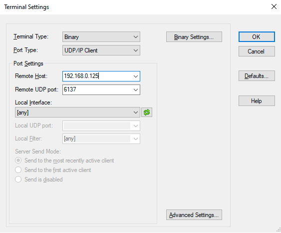
Establishing Connection
Follow the steps to establish connection to the receiver:
Step 1.Connect the receiver to a LAN over Ethernet.
Step 2.Open the terminal application (e.g. YAT).
Step 3.Go to Terminal > Settings.
Step 4.Select the Binary terminal type.
Step 5.Select the UDP/IP Client port type.
Step 6.Add the IP address of the device (eg: 192.168.0.125) and the Remote UDP port number (6137).
Step 7.In View > Radix, choose Hexadecimal.
Step 8.Open the connection
Once the terminal window is opened, you can enter the UDP protocol commands, which are listed in the following sections:
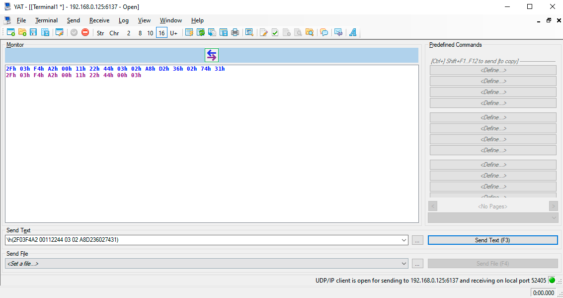
The format of a hexadecimal command in YAT is the following:
\h(<UDP_command>)
5.2. Setup
Before you begin configuration, please make sure of the following:
Step 1.Take note of the MAC address of your devices. You can find this information in the lower left corner of the top of the extenders.
Step 2.Connect your extenders to each other (point-to-point mode) or the switch (virtual hub in host-side extender). Make sure that your PoE+ devices (USB20-1GBE-HS13P and USB20-1GBE-DS4P) are powered either by a PoE+ capable switch or locally with an adapter.
Step 3.Connect your host-side extender to the host computer via a USB cable. Please be aware that the USB20-1GBE-HS13P model can only be powered locally with an adapter or by a PoE+ capable switch.
Step 4.Check that your host (or control) computer is in the same network as your extenders.
Step 5.Power on your devices.
Step 6.Pair the extenders either via the buttons as seen in the Pairing the Devices section or with the Pairing to a Device message.
5.3. Protocol Description
The SwitchableUSB: Device Configuration Network Protocol described in this chapter works on top of User Datagram Protocol (UDP). The protocol is created to be able to discover and configure USB20 Extender series devices on a local Ethernet network. The messages can be sent to the device as UDP packages via port no. 6137. In the following examples the packages are sent in Hexadecimal format.
Generic Packet Structure
|
Format |
Explanation |
|
Magic Number |
A value (0x2F03F4A2) that ensures that the following data is a configuration message. |
|
Message ID |
When the client sends a request, it chooses any value to insert in this field. The extender responding to the request will set this field in the reply to the same value. |
|
Protocol Version |
An integer from 0-255. All devices will support protocol 0 and one other protocol version. The Replying Device Information message will inform the client which version of the protocol it must speak in order to communicate with the extender. |
|
Command |
An integer from 0-255. This is the identifier of the command. The combination of the protocol version and the command identify a unique message type. |
▪All multi-byte fields are packed as big endian.
▪Messages are at least 10 bytes and at most 136 bytes in length.
▪Any string fields should be encoded using UTF-8.
Example
»2F03F4A2 00112244 00 00
5.3.1. Legend for the Commands
|
Format |
Description |
|
» |
Sent request |
|
« |
Received response |
INFO:Spaces seen in the examples are for enhancing readability, they can be left out of the commands.
5.4. Network Broadcast
5.4.1. Subnet Broadcast
To broadcast a packet to subnet you only have to use the broadcast IP of the subnet. For example to broadcast to a network configured as an IP range of 192.168.5.xxx, and a netmask of 255.255.255.0, the IP 192.168.5.255 is the broadcast IP address. In case of a network configured as an IP range of 10.xxx.xxx.xxx, and a netmask of 255.0.0.0, the IP 10.255.255.255 is the broadcast IP address.
Since routers drop broadcast IP packets with a destination outside of the network of the source, these broadcast packages must originate in the same network as the target devices.
5.4.2. All Local Subnet Broadcast
By broadcasting to the IP address 255.255.255.255 a broadcast packet can be sent out without knowing previously what the local network is. Microsoft Windows will, however, only send the packet out through the first configured network interface, so on a computer with multiple interfaces, each interface should send a separate broadcast network packet.
5.4.3. Mismatched Network Configuration
When broadcasting to a subnet using the network broadcast address (e.g. 192.168.5.255) and the extender is configured for a different network (e.g. IP=10.0.9.23 and netmask=255.0.0.0), the extender will not respond to the broadcast, as it will not recognize the IP address as a valid broadcast.
This should not happen when a proper DHCP server allocates addresses from the same pool for the network, however, it may happen when assigning static IP addresses or moving units between networks. In case of this occurence, the extender must be reset to a DHCP address in the way seen in the section Setting a Dynamic IP Address. After this a static IP address can be assigned to the unit again.
5.5. Generic Replies
5.5.1. Acknowledge
This message is a generic ACK message that will be sent in response to all requests made by clients that do not require returning an additional data payload in the response. The Message ID field should be sufficient to determine which message is being acknowledged.
|
Byte Offset |
||
|
0 |
Magic Number |
|
|
2 |
||
|
4 |
Message ID |
|
|
6 |
||
|
8 |
Protocol Version = 0 |
Command = 3 |
Example
«2F03F4A2 00112244 00 03
5.5.2. Negative Acknowledge
This message is a generic NAK message that may be sent in response to a Pairing to a Device, Removing Device Pairing or Requesting Device Topology message. It indicates to the client that their request was received, but that no action will be taken as a result of that message. The Message ID field should be sufficient to determine which message this is a response to.
|
Byte Offset |
||
|
0 |
Magic Number |
|
|
2 |
||
|
4 |
Message ID |
|
|
6 |
||
|
8 |
Protocol Version = 3 |
Command = 8 |
Example
«2F03F4A2 00112244 03 08
5.6. Supported Messages
5.6.1. Requesting and Replying Device Information
Request
This message is sent from the client to an extender in order to evoke a Replying Device Information message. This message can be sent in a broadcast UDP message in order to discover all of the configurable USB extenders on the local network.
|
Byte Offset |
||
|
0 |
Magic Number |
|
|
2 |
||
|
4 |
Message ID |
|
|
6 |
||
|
8 |
Protocol Version = 0 |
Command = 0 |
Reply
This message is sent from an extender to a client in response to a Requesting Device Information message.
|
Byte Offset |
||
|
0 |
Magic Number |
|
|
2 |
||
|
4 |
Message ID |
|
|
6 |
||
|
8 |
Protocol Version = 0 |
Command = 1 |
|
10 |
MAC Address |
|
|
12 |
||
|
14 |
||
|
16 |
IP Address |
|
|
18 |
||
|
20 |
Network Aquisition Mode |
Supported Protocol Version |
|
22 |
Vendor |
|
|
52 |
||
|
54 |
Product |
|
|
84 |
||
|
86 |
Revision |
|
|
96 |
||
Field Descriptions
|
Field Data Type |
Explanation |
Values |
Value description |
|
MAC address |
The MAC address of the device |
||
|
IP address |
The current IP address of the device |
||
|
Network Acquisition Mode |
0 |
DHCP |
|
|
Supported Protocol Version |
This number specifies what protocol version the device supports beside protocol 0. |
||
|
Vendor |
A 32-byte, NUL-terminated string containing the vendor name of the device. |
||
|
Product |
A 32-byte, NUL-terminated string containing the product name of the device. |
||
|
Revision |
A 12-byte, NUL-terminated string containing the revision number of the device. |
Example
»2F03F4A2 00112244 00 00
«2F03F4A2 00112244 00 01 A8D236027431 C0A8007D 00 03
4C69676874776172652056697375616C20456E67696E656572696E6700000000
55534232302D314742452D485331300000000000000000000000000000000000 322E302E3600000000000000
5.6.2. Ping
This message is sent from a client to the device to check if a device is active. An Acknowledge message will be sent by the device in response.
Request
|
Byte Offset |
||
|
0 |
Magic Number |
|
|
2 |
||
|
4 |
Message ID |
|
|
6 |
||
|
8 |
Protocol Version = 0 |
Command = 2 |
Example
»2F03F4A2 00112244 00 02
«2F03F4A2 00112244 00 03
5.6.3. Requesting and Replying Extended Device Information
Request
Sent by a client to an extender in order to obtain additional information about the device that is not included in the Replying Device Information message from protocol 0.
|
Byte Offset |
||
|
0 |
Magic Number |
|
|
2 |
||
|
4 |
Message ID |
|
|
6 |
||
|
8 |
Protocol Version = 3 |
Command = 0 |
Reply
Sent by an extender to a client in response to a Requesting Extended Device Information message.
|
Byte Offset |
||
|
0 |
Magic Number |
|
|
2 |
||
|
4 |
Message ID |
|
|
6 |
||
|
8 |
Protocol Version = 3 |
Command = 1 |
|
10 |
LEX/REX |
Paired with MAC address |
|
12 |
||
|
14 |
||
|
16 |
||
Last six bytes can be repeated 0 or 1 times for an extender in point-to-point mode, or 0 to 7 times for a host side extender with virtual hub enabled.
Field Descriptions
|
Field Data Type |
Explanation |
Values |
Value description |
|
LEX/REX |
This determines whether the responding device is a host-side extender (LEX), or a device-side extender (REX). |
0 |
Host-side extender |
|
Paired with MAC address |
MAC address of an extender that this device is paired with. This field is optional and may be repeated up to 7 times. |
Example
»2F03F4A2 00112244 03 00
«2F03F4A2 00112244 03 01 00 A8D23602B357001B1302E3A4
This message is sent by a client to instruct an extender to try to pair with a different extender specified in the message. The client must send this message to both the host-side and device-side extenders, the contents adjusted respectively, but the order of the two messages does not matter. The extender will respond with an Acknowledge message if it is able to pair with a new device or a Negative Acknowledge message otherwise.These replies only mean that an attempt will be made to establish a link between the extenders, not that a link is already established. #pairing
In case of pairing several device-side extenders to a host-side extender, this step must be repeated for each pairing.
Field Descriptions
|
Field Data Type |
Explanation |
Values |
Value description |
|
Pairing to device MAC address |
The MAC address that the client is telling the extender to attempt to pair with. |
Request
|
Byte Offset |
||
|
0 |
Magic Number |
|
|
2 |
||
|
4 |
Message ID |
|
|
6 |
||
|
8 |
Protocol Version = 3 |
Command = 2 |
|
10 |
Pairing to Device MAC Address |
|
|
12 |
||
|
14 |
||
Example
»2F03F4A2 00112244 03 02 A8D236027431
«2F03F4A2 00112244 00 03
»2F03F4A2 00112244 03 02 A8D23602B357
«2F03F4A2 00112244 00 03
5.6.5. Removing Device Pairing
Sent by a client to an extender, instructing it to discard any existing pairing it has. This will effectively disconnect any USB devices that were downstream of the remote extender. The client must send this message to each of the extenders in the pairing. The extenders will respond with an Acknowledge message or with a Negative Acknowledge if it is already unpaired or paired to a different extender.
Field Descriptions
|
Field Data Type |
Explanation |
Values |
Value description |
|
Paired MAC address |
The MAC address that the client is telling the extender to disassociate from. |
Request
|
Byte Offset |
||
|
0 |
Magic Number |
|
|
2 |
||
|
4 |
Message ID |
|
|
6 |
||
|
8 |
Protocol Version = 3 |
Command = 3 |
|
10 |
Paired MAC Address |
|
|
12 |
||
|
14 |
||
Example
»2F03F4A2 00112244 03 03 A8D236027431
«2F03F4A2 00112244 00 03
»2F03F4A2 00112244 03 03 A8D23602B357
«2F03F4A2 00112244 00 03
5.6.6. Requesting and Replying Device Topology
Request
Sent by a client to a host-side extender in order to obtain the set of USB devices in the system. A device-side extender will respond with a Negative Acknowledge to this message.
|
Byte Offset |
||
|
0 |
Magic Number |
|
|
2 |
||
|
4 |
Message ID |
|
|
6 |
||
|
8 |
Protocol Version = 3 |
Command = 4 |
Reply
A host-side extender will send this message in response to a Requesting Device Topology message. The length of this message varies depending on the number of devices in the system. The combination of the information is enough for a client to build and display a device tree.
|
Byte Offset |
||
|
0 |
Magic Number |
|
|
2 |
||
|
4 |
Message ID |
|
|
6 |
||
|
8 |
Protocol Version = 3 |
Command = 5 |
|
10 |
USB Address |
USB Address Of Parent |
|
12 |
Port on Parent |
Is Device a Hub |
|
14 |
USB Vendor ID |
|
|
16 |
USB Product ID |
|
Bytes 10 to 16 can be repeated 0 to 32 times according to the number of USB devices.
INFO:Maximum number of USB devices is 32.
Field Descriptions
|
Field Data Type |
Explanation |
Values |
Value description |
|
USB Address |
An integer from 0 to 127. |
||
|
USB Address of Parent |
An integer from 1 to 127. If a USB Address is seen that is not listed as the USB Address of Parent for any of the devices, then that device is the root of the device topology. |
||
|
Port on Parent |
An integer from 1 to 127. 0 is not a valid number for a port on a hub, so this field will only be 0 if there is no USB device upstream before the host. |
||
|
Is Device a Hub |
0 |
False |
|
|
USB Vendor ID |
The USB Vendor ID from the device descriptor. |
||
|
USB Product ID |
The USB Product ID from the device descriptor. |
Example
»2F03F4A2 00112244 03 04
«2F03F4A2 00112244 03 05 2A27020004580186 2724010104B46506 24000001089D0001
5.6.7. Using DHCP
Sent by a client to an extender to tell it to use DHCP to obtain an IP address. This message may be sent either as a UDP broadcast packet or a packet directed to a specific IP address known already. Regardless of whether the message was sent as a broadcast or not, the device will only switch to DHCP mode if the Target MAC Address field matches its own MAC address. When a valid Using DHCP message is received, the extender will send an Acknowledge message before discarding its static address configuration and aquiring an IP address via DHCP. If the Using DHCP message is sent to a device already in DHCP mode, it will still send an Acknowledge response, but no further actions are taken such as IP renewal. The client is able to tell the mode an extender is in by inspecting the Network Aquisition Mode field of the Replying Device Information message. #dhcp
Request
|
Byte Offset |
||
|
0 |
Magic Number |
|
|
2 |
||
|
4 |
Message ID |
|
|
6 |
||
|
8 |
Protocol Version = 3 |
Command = 6 |
|
10 |
Target MAC Address |
|
|
12 |
||
|
14 |
||
Field Descriptions
|
Field Data Type |
Explanation |
|
Target MAC address |
The MAC address of the device that will be set to use DHCP to obtain an IP address. |
Example
»2F03F4A2 00112244 03 06 A8D236027431
«2F03F4A2 00112244 00 03
5.6.8. Using Static IP
Sent by a client to an extender to tell it to use the static network configuration contained in this message. The IP, subnet mask and default gateway, as well as the network configuration are stored in permanent storage, so the device will keep the same network configuration after being power cycled. Similarly to the Using DHCP message, this message can be broadcast or sent to a specific device. Given that the Target MAC Address field matches the MAC address of the device, it will always respond with an Acknowledge message. Sending a Using Static IP message to a device already in a static configuration will enable the client to change the IP, subnet mask or default gateway of the device.
Request
|
Byte Offset |
||
|
0 |
Magic Number |
|
|
2 |
||
|
4 |
Message ID |
|
|
6 |
||
|
8 |
Protocol Version = 3 |
Command = 7 |
|
10 |
Target MAC Address |
|
|
12 |
||
|
14 |
||
|
16 |
IPv4 Address |
|
|
18 |
||
|
20 |
Subnet Mask |
|
|
22 |
||
|
24 |
Default Gateway |
|
|
26 |
||
Field Descriptions
|
Field Data Type |
Explanation |
|
Target MAC Address |
The MAC address of the device that will be set to use static network configuration. |
|
IPv4 Address |
The IPv4 address being assigned to this device encoded as a 32-bit integer. |
|
Subnet Mask |
The subnet mask of the network the device is on. |
|
Default Gateway |
Sets the default gateway of the device. |
Example
»2F03F4A2 00112244 03 07 001B1302E3A4 C0A8007E FFFFFF00 C0A80001
«2F03F4A2 00112244 00 03
5.6.9. Using Filtering Strategy
Sent by a client to an extender to set it to use a certain type of filtering strategy contained in the message. The filtering strategy denotes the type of devices to be filtered out by the extenders. An Acknowledge message will be sent back to the client if the extender supports device class filtering and a valid strategy was selected. Otherwise, a Negative Acknowledge will be sent to the client.
Field Descriptions
|
Field Data Type |
Values |
Value description |
|
Filtering Strategy |
0 |
Allow all devices |
Request
|
Byte Offset |
||
|
0 |
Magic Number |
|
|
2 |
||
|
4 |
Message ID |
|
|
6 |
||
|
8 |
Protocol Version = 3 |
Command = 9 |
|
10 |
Filtering Strategy |
|
Example
»2F03F4A2 00112244 03 09 02
«2F03F4A2 00112244 00 03
5.6.10. Turning the LED Locator On
This message is sent from the client to an extender. Upon receiving this message, the LED pattern is started on the device. A specific extender can be located physically with this message.
Request
|
Byte Offset |
||
|
0 |
Magic Number |
|
|
2 |
||
|
4 |
Message ID |
|
|
6 |
||
|
8 |
Protocol Version = 3 |
Command = 10 |
Example
»2F03F4A2 00112244 03 0A
«2F03F4A2 00112244 00 03
5.6.11. Turning the LED Locator Off
This message is sent from the client to an extender. Upon receiving this message, the LED pattern is stopped on the device. It only works when the LED pattern is activated on the extender.
Request
|
Byte Offset |
||
|
0 |
Magic Number |
|
|
2 |
||
|
4 |
Message ID |
|
|
6 |
||
|
8 |
Protocol Version = 3 |
Command = 11 |
Example
»2F03F4A2 00112244 03 0B
«2F03F4A2 00112244 00 03
5.6.12. Reseting Device
This message is sent from the client to the extender. Upon receiving this message, the device resets.
Request
|
Byte Offset |
||
|
0 |
Magic Number |
|
|
2 |
||
|
4 |
Message ID |
|
|
6 |
||
|
8 |
Protocol Version = 3 |
Command = 12 |
Example
»2F03F4A2 00112244 03 0C
«2F03F4A2 00112244 00 03
5.6.13. Requesting and Replying Configuration Response Data
Request
This message is sent from the client to an extender in order to evoke a Replying Configuration Response Data message.
|
Byte Offset |
||
|
0 |
Magic Number |
|
|
2 |
||
|
4 |
Message ID |
|
|
6 |
||
|
8 |
Protocol Version = 3 |
Command = 13 |
Reply
This message is sent from an extender to a client in response to a Requesting Configuration Response Data message.
|
Byte Offset |
||
|
0 |
Magic Number |
|
|
2 |
||
|
4 |
Message ID |
|
|
6 |
||
|
8 |
Protocol Version = 3 |
Command = 14 |
|
10 |
High Speed Status |
MSA Status |
|
12 |
Vhub Status |
Current Filter Status |
|
14 |
IP Acquisition Mode |
Reserved |
|
16 |
MAC Address |
|
|
18 |
||
|
20 |
||
|
22 |
Reserved |
|
|
24 |
Paired with MAC Address |
|
|
64 |
||
|
66 |
Port Number |
|
|
68 |
IP Address |
|
|
70 |
||
|
72 |
Subnet Mask |
|
|
74 |
||
|
76 |
Default Gateway |
|
|
78 |
||
|
80 |
DHCP Server |
|
|
82 |
||
|
84 |
Number of Vhub Ports |
Reserved |
|
86 |
VID |
|
|
88 |
PID |
|
|
90 |
Brand ID |
|
|
92 |
Vendor |
|
|
120 |
||
|
122 |
Product |
|
|
152 |
||
|
154 |
Revision |
|
|
166 |
||
Field Descriptions
|
Field Data Type |
Explanation |
Values |
Value description |
|
High Speed |
0 |
Disabled |
|
|
MSA |
0 |
Disabled |
|
|
Vhub |
0 |
Disabled |
|
|
Current Filter Status |
0 |
Allow all devices |
|
|
IP Acquision Mode |
0 |
DHCP |
|
|
Reserved |
This field is reserved and is set to 0. |
||
|
MAC Address |
The MAC address of the device. |
||
|
Paired with MAC Address |
MAC address of an extender that this device is paired with. This field is optional and may be repeated up to 7 times. |
||
|
Port Number |
The port number that this device is connected to. |
||
|
IP Address |
The current IP address of the device. |
||
|
Subnet Mask |
The subnet mask of the device. |
||
|
Default Gateway |
The default gateway for the device. |
||
|
DHCP Server |
The DHCP server of the device. |
||
|
Num of Vhub ports |
The number of downstream ports of the device. |
||
|
VID |
The Vendor ID of the device. |
||
|
PID |
The Product ID of the device. |
||
|
Brand ID |
The Brand ID of the device. |
0 |
Non-vendor locked device |
|
Vendor |
A 32-byte NUL-terminated string containing the vendor name of the device. |
||
|
Product |
A 32-byte NUL-terminated string containing the product name of the device. |
||
|
Revision |
A 12-byte NUL-terminated string containing the revision number of the device. |
Example
»2F03F4A2 00112244 03 0D
«2F03F4A2 00112244 03 0E 01 00 01 00 00 00 A8D23602B357 00 00
A8D236027431000000000000000000000000000000000000000000000000000000000000000000000000 17F9 C0A8007F FFFFFF00 C0A80001 C0A80001 07 00 6F27 6E01 0000
4C69676874776172652056697375616C20456E67696E656572696E6700000000
55534232302D314742452D445334000000000000000000000000000000000000 322E302E3600000055534220
5.6.14. Requesting and Replying Link Status
Request
This message is sent from the client to an extender in order to obtain the link status of the paired units.
|
Byte Offset |
||
|
0 |
Magic Number |
|
|
2 |
||
|
4 |
Message ID |
|
|
6 |
||
|
8 |
Protocol Version = 3 |
Command = 15 |
Reply
This message is sent from the extender to the client in response to a Requesting Link Status Information message. The message will contain information for all 7 devices that could be paired. If the number of paired devices is less than 7, the unpaired fields are set to 0. Thus, the size of the structure sent remains the same regardless of the number of paired units.
|
Byte Offset |
||
|
0 |
Magic Number |
|
|
2 |
||
|
4 |
Message ID |
|
|
6 |
||
|
8 |
Protocol Version = 3 |
Command = 16 |
|
10 |
Link Status of Device 1 |
Link Status of Device 2 |
|
12 |
Link Status of Device 3 |
Link Status of Device 4 |
|
14 |
Link Status of Device 5 |
Link Status of Device 6 |
|
16 |
Link Status of Device 7 |
Reserved |
|
18 |
MAC Address of Device 1 |
|
|
20 |
||
|
22 |
||
|
24 |
MAC Address of Device 2 |
|
|
26 |
||
|
28 |
||
|
30 |
MAC Address of Device 3 |
|
|
32 |
||
|
34 |
||
|
36 |
MAC Address of Device 4 |
|
|
38 |
||
|
40 |
||
|
42 |
MAC Address of Device 5 |
|
|
44 |
||
|
46 |
||
|
48 |
MAC Address of Device 6 |
|
|
50 |
||
|
52 |
||
|
54 |
MAC Address of Device 7 |
|
|
56 |
||
|
58 |
||
Field Descriptions
|
Field Data Type |
Explanation |
Values |
Value description |
|
Link Status |
0 |
Device not paired |
|
|
Reserved |
This field is reserved and is set to 0. |
||
|
Paired with MAC Address |
Each MAC address uses 6 bytes and the field value will be set to 0 if there is no device paired. |
Example
»2F03F4A2 00112244 03 0F
«2F03F4A2 00112244 03 10 02 01 00 00 00 00 00 00 A8D23602B357001B1302E3A4000000000000000000000000000000000000000000000000000000000000
5.6.15. Removing All Pairings
This command is sent by the client to an extender to instruct it to clear all of its pairings. This message may be sent to an extender that has no current pairings, but it will have no effect.
Request
|
Byte Offset |
||
|
0 |
Magic Number |
|
|
2 |
||
|
4 |
Message ID |
|
|
6 |
||
|
8 |
Protocol Version = 3 |
Command = 17 |
Example
»2F03F4A2 00112244 03 11
«2F03F4A2 00112244 00 03
5.6.16. Force Pairing to Device
This command is sent by the client to an extender to instruct it to clear all of its existing pairings and then try to pair with a different extender specified in the message. The client must send this message to both a host-side extender and a device-side extender to instruct them to be paired together, but the order of the two messages does not matter. The extender will respond with an Acknowledge message if it is able to pair with a new device or a Negative Acknowledge otherwise. #pairing
INFO:The Acknowledge message only indicates an attempt will be made to establish a link between the extenders, not that a link is already established.
Field Descriptions
|
Field Data Type |
Explanation |
|
Force Pair to Device MAC Address |
The MAC address that the client is telling the extender to attempt to pair with. |
Request
|
Byte Offset |
||
|
0 |
Magic Number |
|
|
2 |
||
|
4 |
Message ID |
|
|
6 |
||
|
8 |
Protocol Version = 3 |
Command = 18 |
|
10 |
Force Pair to Device MAC Address |
|
|
12 |
||
|
14 |
||
Example
»2F03F4A2 00112244 03 12 A8D23602B357
«2F03F4A2 00112244 00 03
»2F03F4A2 00112244 03 12 A8D236027431
«2F03F4A2 00112244 00 03
5.6.17. Reseting Force Pairing to Device
This command is the same as the Force Pairing to Device command, but it resets the system after the pairing with the other extender happens.
INFO:This command only works when sent to a host-side extender. When sent to a device-side extender, it will reset the device, but pairing will not happen.
Field Descriptions
|
Field Data Type |
Explanation |
|
Force Pair to Device MAC Address |
The MAC address that the client is telling the extender to attempt to pair with. |
Request
|
Byte Offset |
||
|
0 |
Magic Number |
|
|
2 |
||
|
4 |
Message ID |
|
|
6 |
||
|
8 |
Protocol Version = 3 |
Command = 19 |
|
10 |
Force Pair to Device MAC Address |
|
|
12 |
||
|
14 |
||
Example
»2F03F4A2 00112244 03 13 A8D23602B357
«2F03F4A2 00112244 00 03
5.6.18. Setting the Product ID
This command sets the product ID. The product ID is 32 bytes long and can only be written once. By default, it is set to USB Over Network. If it is set once and the client tries to set it again, it will respond with a Negative Acknowledge message and will not change.
Field Descriptions
|
Field Data Type |
Explanation |
|
Product ID |
32-byte-long product ID that the client wants to set. |
Request
|
Byte Offset |
||
|
0 |
Magic Number |
|
|
2 |
||
|
4 |
Message ID |
|
|
6 |
||
|
8 |
Protocol Version = 3 |
Command = 20 |
|
10 |
Product ID |
|
|
40 |
||
Example
»2F03F4A2 00112244 03 14
55534232302D314742452D445334500000000000000000000000000000000000
«2F03F4A2 00112244 00 03
»2F03F4A2 00112244 03 14
55534232302D314742452D445334500000000000000000000000000000000000
«2F03F4A2 00112244 03 08
5.6.19. Writing the Extended Configuration Variable
This command writes the extended configuration variable. It is used to control the following configuration parameters:
▪Simultaneous Users Interaction (SUI) and Mass Storage Acceleration (MSA)
▪Enabling/Disabling DHCP option
▪DCF configuration
The client will set the bit of configuration mask corresponding to which configuration variable they want to change and set the configuration variable as defined below in the field descriptions. The system will reset after a variable is set.
ATTENTION!Please be aware that while this command is packed as big endian, depending on the terminal application and the Operation System, it may be reversed by the application to display as little endian.
Field Descriptions
|
Field Data Type |
Explanation |
Values |
Value description |
|
Configuration Mask |
This is a 16-bit mask, in which only the first 4 are used. The remaining are reserved and set to 0. |
Bit 0 |
Change only SUI and MSA fields in the configuration variable. |
|
Configuration Variable |
This is the 32 bits defined as it follows: |
||
|
Simultaneous Users Interaction (SUI) and Mass Storage Acceleration (MSA) (2-bit field starting at bit 0) |
0 |
SUI off, MSA off |
|
|
Enabling/Disabling the DHCP option 60 (1-bit field, at bit 2) |
|||
|
Reserved, set to 0 (1-bit field, at bit 3) |
|||
|
Disabling DCF or Set DCF options - DCF configuration field (4-bit field, starting at bit 4) |
0 |
Allow all devices (DCF disabled) |
Request
|
Byte Offset |
||
|
0 |
Magic Number |
|
|
2 |
||
|
4 |
Message ID |
|
|
6 |
||
|
8 |
Protocol Version = 3 |
Command = 50 |
|
10 |
Configuration Mask |
|
|
12 |
Extended Configuration Variable |
|
|
14 |
||
Example
»2F03F4A2 00112244 03 32 0100 01000000
«2F03F4A2 00112244 00 03
INFO:Please take note that depending on the SUI setting, the extender may take up several USB tiers. If SUI is turned off, the extender takes up one USB tier. If SUI is turned on, it takes up two USB tiers. For optimal operation please make sure you do not exceed the maximum tier level (generally 7).
5.6.20. Requesting and Replying the Extended Configuration Variable
Request
This command is sent from the client to the extender to request the extended configuration variable.
|
Byte Offset |
||
|
0 |
Magic Number |
|
|
2 |
||
|
4 |
Message ID |
|
|
6 |
||
|
8 |
Protocol Version = 3 |
Command = 51 |
Reply
This command is a response to the Requesting Extended Configuration Variable command, sent from the extender to the client. It offers the extended configuration variable.
|
Byte Offset |
||
|
0 |
Magic Number |
|
|
2 |
||
|
4 |
Message ID |
|
|
6 |
||
|
8 |
Protocol Version = 3 |
Command = 52 |
|
10 |
Extended Configuration Variable |
|
|
12 |
||
Field Descriptions
|
Field Data Type |
Explanation |
Values |
Value description |
|
Configuration Variable |
This is the 32 bits defined as it follows: |
||
|
Simultaneous Users Interaction (SUI) and Mass Storage Acceleration (MSA) (2-bit field starting at bit 0) |
0 |
SUI off, MSA off |
|
|
Enabling/Disabling the DHCP option 60 (1-bit field, at bit 2) |
|||
|
Reserved, set to 0 (1-bit field, at bit 3) |
|||
|
Disabling DCF or Set DCF options - DCF configuration field (4-bit field, starting at bit 4) |
0 |
Allow all devices (DCF disabled) |
Example
»2F03F4A2 00112244 03 33
«2F03F4A2 00112244 03 34 00000001
First, check the front panel LEDs and take the necessary steps according to their states. For more information about status LEDs, refer to the Status LEDs section.
Legend

|
Link to the section of connections/cabling. |

|
Link to the section of front panel operation. |

|
Link to the section of the built-in web page. |

|
Link to the section of LW3 protocol commands. |
|
Symptom |
Root cause |
Action |
Refer to |
|
|
Power |
||||
|
The extender does not start |
The extender does not receive sufficient power |
If the Power LED is lighting red (for PoE+ capable extenders), the power supply is insufficient. Please use PoE+ power sources or local powering. |

|
|
|
USB signal |
||||
|
The signal does not go through |
Extenders are not paired |
Check if the extenders are paired. Be aware that pairing must be started on both devices. |

|
|

|
||||
|
Device filtering is turned on |
Make sure that your filtering settings allow the signal of the desired device to pass through the system. |

|
||
|
The extender cannot be reached |
Check the CATx cable connecting to the extender. |
|||
|
Communication |
||||
|
Pairing does not happen |
The number of paired devices reached the limit |
Make sure that the extenders you are trying to pair have not reached the maximum number of paired devices. Please note that device-side extenders can only be paired with one host-side extender, while host-side extenders can be paired to 7 device-side extenders simultaneously. |

|
|
|
Incorrect MAC address |
Please make sure that you enter the MAC address of the device you are trying to pair to correctly. In case of pairing it is easy to mix up depending on which device you are sending the request to. |

|
||
|
Incorrect IP address |
Please make sure that the IP address you are using for communication is correct. In case of pairing it is easy to mix up depending on which device you are sending the request to. |
|||
|
There is no response from the device |
Incorrect request |
In case of using hexadecimal requests, it may happen that the number or the value of the bytes is incorrect. Please make sure that the request is entered correctly. |
||
6.2. How to Speed Up the Troubleshooting Process
Lightware’s technical support team is always working hard to provide the fastest support possible. Our team’s response time is one of the best in the industry and in the toughest of cases we can directly consult with the hardware or software engineer who designed the product to get the information from the most reliable source.
However, the troubleshooting process can be even faster… with your help.
There are certain pieces of information that push us in the right direction to find the root cause of the problem. If we receive most of this information in the first e-mail or it is gathered at the time when you call us, then there is a pretty high chance that we will be able to respond with the final solution right away.
This information is the following:
▪Schematic (a pdf version is preferred, but a hand drawing is sufficient).
▪Serial number(s) of the device(s) (it is either printed somewhere on the box or you can query it using the control software).
▪Firmware versions of the devices (please note that there may be multiple CPUs or controllers in the device and we need to know all of their firmware versions, a screenshot is the best option).
▪Cable lengths and types (in our experience, it’s usually the cable).
▪Patch panels, gender changers or anything else in the signal path that can affect the transmission.
▪Signal type (resolution, refresh rate, color space, deep color).
▪Actions to take in order to re-create the problem (if we cannot reproduce the problem, it is hard for us to find the cause).
▪Photo or video about the problem (‘image noise’ can mean many different things, it’s better if we see it too).
The more of the information above you can give us, the better. Please send this information to the Lightware Support Team (support@lightware.com) to speed up the troubleshooting process.
Tables, drawings, guides, hashtag keyword list and technical details as follows:
General
|
Compliance |
CE, UKCA |
|
Electrical safety |
EN 62368-1:2024 |
|
EMC compliance (emission) |
EN 55032:2015+A1:2020 |
|
EMC compliance (immunity) |
EN 55035:2017+A11:2020 |
|
RoHS compliance |
EN 63000:2018 |
|
Warranty |
3 years |
|
Operating temperature |
0°C to 55°C (32°F to 122°F) |
|
Operating humidity |
20-80%, non-condensing |
Power
|
Power supply option |
Power adapter |
|
Supported power source |
100-240V AC; 50/60 Hz |
|
Power consumption (USB20-1GBE-HS10) |
1W |
|
Heat dissipation |
4 BTU/h |
|
Power consumption (USB20-1GBE-DS4) |
9W |
|
Heat dissipation |
31 BTU/h |
|
Power over Ethernet + (PoE+) 1 |
via RJ45 connector (IEEE802.3at) |
1 Only for models USB20-1GBE-HS13P and USB20-1GBE-DS4P.
Power supply
|
Supplied power |
24 V DC, 1 A |
|
DC power connector |
Locking DC connector (2.1/5.5 mm pin) |
Enclosure
|
Rack mountable |
yes, with mounting accessories |
|
Enclosure material |
1 mm steel |
USB20-1GBE-HS10
|
Dimensions (mm) |
100.4(W), 26(H), 76.3(D) |
|
Dimensions (inch) |
3.95(W), 1.02(H), 3(D) |
|
Weight |
244 g (0.54 lb) |
USB20-1GBE-HS13P
|
Dimensions (mm) |
100.4(W), 26(H), 85.6(D) |
|
Dimensions (inch) |
3.95(W), 1.02(H), 3.37(D) |
|
Weight |
282 g (0.62 lb) |
USB20-1GBE-DS4
|
Dimensions (mm) |
100.4(W), 26(H), 76.3(D) |
|
Dimensions (inch) |
3.95(W), 1.02(H), 3(D) |
|
Weight |
254 g (0.56 lb) |
USB20-1GBE-DS4P
|
Dimensions (mm) |
100.4(W), 26(H), 85.6(D) |
|
Dimensions (inch) |
3.95(W), 1.02(H), 3.37(D) |
|
Weight |
276 g (0.61 lb) |
Control ports
Ethernet port
|
Connector type |
RJ45 female connector |
|
Ethernet data rate |
1 GbE |
|
Power over Ethernet |
yes, PoE+ 2 |
|
Default IP address setting |
DHCP is enabled 3 |
2 Only for USB20-1GBE-HS13P and USB20-1GBE-DS4P models.
3 The device is reachable only if DHCP server is in the network.
USB port (USB20-1GBE-HS10 and USB20-1GBE-HS13P models)
|
Connector type |
USB B-type receptacle |
|
USB compliance |
USB 2.0 |
|
Number of TIER to USB 2.0 layer (per extender pair, single port mode) |
2 |
|
Number of TIER to USB 2.0 layer (per extender pair, virtual hub mode) |
3 |
USB port (USB20-1GBE-DS4 and USB20-1GBE-DS4P models)
|
Connector type |
USB A-type receptacle |
|
USB compliance |
USB 2.0 |
INFO:Specifications are subject to change without notice.
USB20-1GBE-DS4
USB20-1GBE-DS4 can be seen in the pictures, but the dimensions are the same for USB20-1GBE-HS10, too.
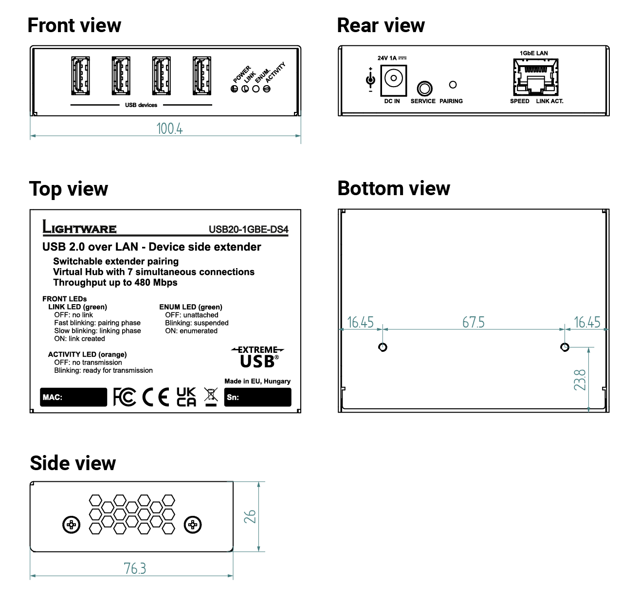
USB20-1GBE-HS13P
USB20-1GBE-HS13P can be seen in the pictures, but the dimensions are the same for USB20-1GBE-DS4P, too.
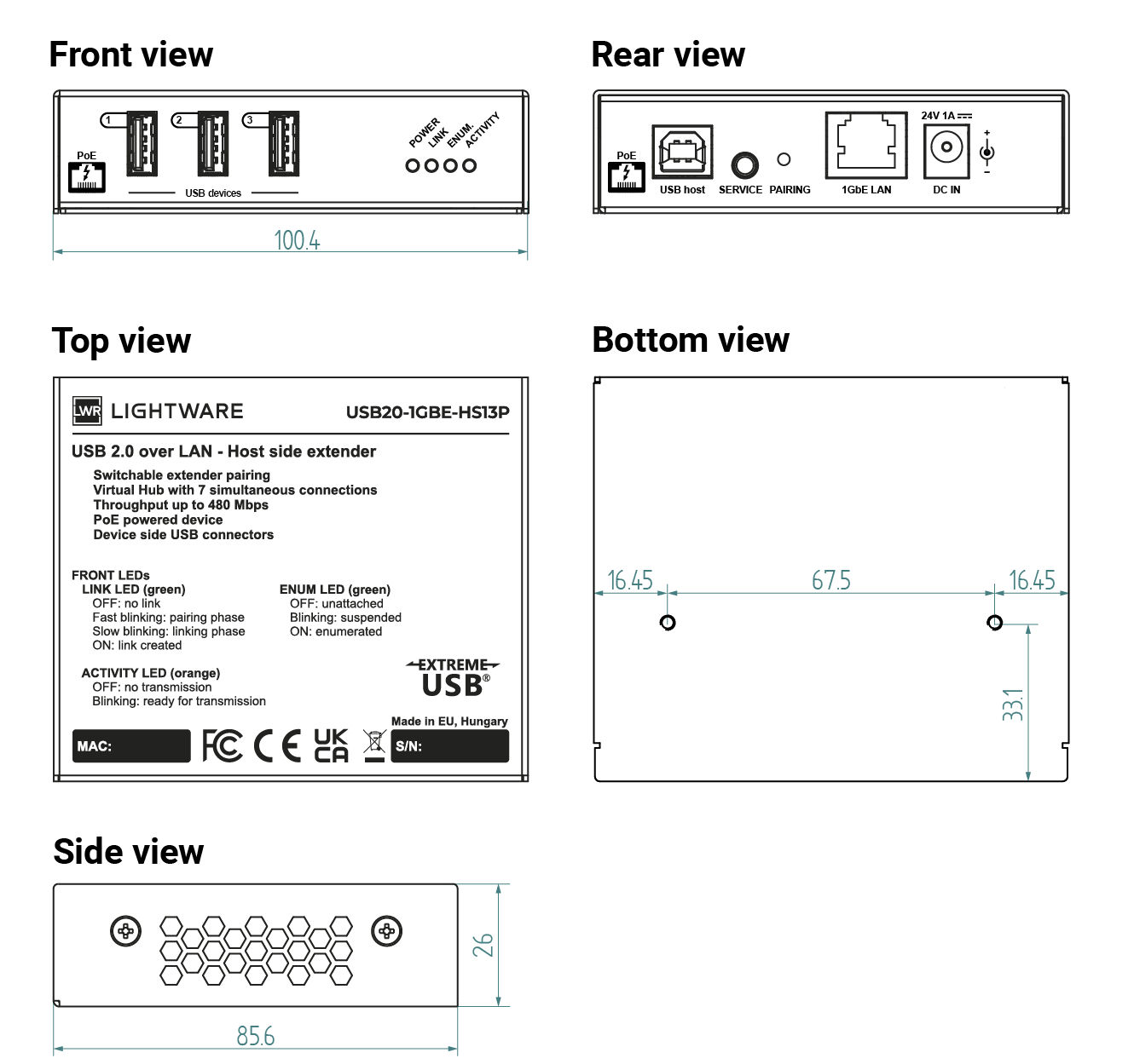
7.3. Hashtag Keyword List
This user manual contains keywords with hashtags (#) to help you find the relevant information as quick as possible.
The format of the keywords is the following:
#<keyword>
The usage of the keywords: use the Search function (Ctrl+F / Cmd+F) of your PDF reader application, type the # (hashtag) character and the wished keyword.
The #new special keyword indicates a new feature/function that has just appeared in the latest firmware or software version.
Example
#dhcp
This keyword is placed at the DHCP (dynamic IP address) setting in the front panel operation, the Lightware Device Controller (LDC) and the LW3 programmer's reference section.
The following list contains all hashtag keywords placed in the document with a short description belonging to them. The list is in alphabetical order by the hashtag keywords.
|
Hashtag Keyword |
Description |
|---|---|
|
#dhcp |
DHCP setting |
|
#pairing |
Pairing of the extenders |

7.4. Further Document Information
Symbol Legend
The following symbols and markings are used in the document:
WARNING!Safety-related information that is highly recommended to read and keep in every case!
ATTENTION!Useful information for performing a successful procedure; it is recommended to read.
DIFFERENCE:Feature or function that is available with a specific firmware/hardware version or product variant.
INFO:A notice, which contains additional information. Procedure can be successful without reading it.
DEFINITION:The short description of a feature or a function.
TIPS AND TRICKS:Ideas that you may have not known yet, but can be useful.
Navigation Buttons
|
Buttons in the PDF version |
Buttons in the HTML version |
|||
|
|
Navigate to the Table of Contents. |
|
Open the main Table of Contents. |
|
|
|
Go back to the previous page. If you clicked on a link previously, you can go back to the source page by pressing the button. |
|
Navigate to the Online User Manuals webpage. |
|
|
|
Navigate to the Bookmark Page. |
|
Navigate to the Bookmark Page in this User Manual. |
|
|
|
Visit www.lightware.com. |
|
Download the PDF version of the User Manual. |
|


About Printing
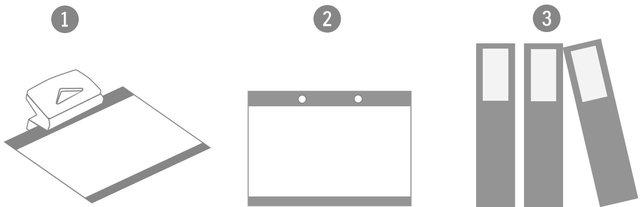
Lightware Visual Engineering supports green technologies and eco-friendly mentality. Thus, this document is made primarily for digital usage. If you need to print out a few pages for any reason, follow the recommended printing settings:
▪Page size: A4
▪Output size: Fit to page or Match page size
▪Orientation: Landscape
TIPS AND TRICKS: Thanks to the size of the original page, a border around the content (gray on the second picture below) makes it possible to organize the pages better. After punching holes in the printed pages, they can easily be placed into a ring folder.
7.5. Limited Warranty Statement
1. Lightware Visual Engineering PLC (Lightware) warrants to all trade and end user customers that any Lightware product purchased will be free from manufacturing defects in both material and workmanship for three (3) years from purchase unless stated otherwise below. The warranty period will begin on the latest possible date where proof of purchase/delivery can be provided by the customer. In the event that no proof can be provided (empty ‘Date of purchase’ field or a copy of invoice), the warranty period will begin from the point of delivery from Lightware.
1.1. 25G and MODEX product series will be subject to a seven (7) year warranty period under the same terms as outlined in this document.
1.2. If during the first three (3) months of purchase, the customer is unhappy with any aspect of a Lightware product, Lightware will accept a return for full credit.
1.3. Any product that fails in the first six (6) months of the warranty period will automatically be eligible for replacement and advanced replacement where available. Any replacements provided will be warranted for the remainder of the original unit’s warranty period.
1.4. Product failures from six (6) months to the end of the warranty period will either be repaired or replaced at the discretion of Lightware. If Lightware chooses to replace the product, then the replacement will be warranted for the remainder of the original unit’s warranty period.
2. The above-stated warranty and procedures will not apply to any product that has been:
2.1. Modified, repaired or altered by anyone other than a certified Lightware engineer unless expressly agreed beforehand.
2.2. Used in any application other than that for which it was intended.
2.3. Subjected to any mechanical or electrical abuse or accidental damage.
2.4. Any costs incurred for repair/replacement of goods that fall into the categories above (2.1., 2.2., 2.3.) will be borne by the customer at a pre-agreed figure.
3. All products to be returned to Lightware require a return material authorization number (RMA) prior to shipment, and this number must be clearly marked on the box. If an RMA number is not obtained or is not clearly marked on the box, Lightware will refuse the shipment.
3.1. The customer will be responsible for in-bound, and Lightware will be responsible for out-bound shipping costs.
3.2. Newly repaired or replaced products will be warranted to the end of the originally purchased product's warranty period.