![]()
USER MANUAL
Matrix Application Mode
UBEX-MMU-X200
UBEX-PRO20-HDMI-F100
UBEX-PRO20-HDMI-F110
UBEX-PRO20-HDMI-F111
UBEX-PRO20-HDMI-F120
UBEX-PRO20-HDMI-F121
UBEX-PRO20-HDMI-F130
UBEX-PRO20-HDMI-R100 2xMM-2xDUO
UBEX-PRO20-HDMI-R100 2xMM-QUAD
UBEX-PRO20-HDMI-R100 2xSM-2xDUO
UBEX-PRO20-HDMI-R100 2xSM-QUAD
UBEX-PRO20-HDMI-R100 2xSM-BiDi-DUO
AV Over IP Multimedia Extender
|
|
|
|
||
|
|
|
|
||
|
|
|
|
||


|
|
|
|
||
|
|
|
|
||
|
|
|
|


Important Safety Instructions
Class I apparatus construction.
This equipment must be used with a mains power system with a protective earth connection. The third (earth) pin is a safety feature, do not bypass or disable it. The equipment should be operated only from the power source indicated on the product.
To disconnect the equipment safely from power, remove the power cord from the rear of the equipment or from the power source. The MAINS plug is used as the disconnect device, the disconnect device shall remain readily operable.
There are no user-serviceable parts inside of the unit. Removal of the cover will expose dangerous voltages. To avoid personal injury, do not remove the cover. Do not operate the unit without the cover installed.
The appliance must be safely connected to multimedia systems. Follow instructions described in this manual.

Ventilation
For the correct ventilation and to avoid overheating, ensure enough free space around the appliance. Do not cover the appliance, leave the ventilation holes free and never block or bypass the ventilators (if there are any).
WARNING
To prevent injury, the apparatus is recommended to be securely attached to the floor/wall, or mounted in accordance with the installation instructions. The apparatus shall not be exposed to dripping or splashing, and no objects filled with liquids, such as vases, shall be placed on the apparatus. No naked flame sources, such as lit candles, should be placed on the apparatus.
Waste Electrical & Electronic Equipment (WEEE)

This marking shown on the product or its literature indicates that it should not be disposed with other household wastes at the end of its working life. To prevent possible harm to the environment or human health from uncontrolled waste disposal, please separate this from other types of wastes and recycle it responsibly to promote the sustainable reuse of material resources. Household users should contact either the retailer where they purchased this product or their local government office for details of where and how they can take this item for environmentally safe recycling. Business users should contact their supplier and check the terms and conditions of the purchase contract. This product should not be mixed with other commercial wastes for disposal.
Caution: Laser product


Common Safety Symbols
|
Symbol |
Description |

|
Direct current |

|
Alternating current |

|
Protective conductor terminal |

|
Equipotential Connector |
.png)
|
On (Power) |
.png)
|
Off (Power) |

|
Double insulation |

|
Caution, possibility of eletric shock |

|
Caution |

|
Laser radiation |

|
Warning, Rotating fan |

|
Caution: for indoor use only |
Applied SW/FW/HW Environment
All presented functions refer to the indicated products. The descriptions have been made while testing these functions in accordance with the indicated Hardware/Firmware/Software environment:
|
Item |
Version |
|
|
Lightware Device Controller (LDC) software |
v2.22.0b2 |
|
|
Lightware Device Updater V2 (LDU2) software |
v2.36.0b8 |
|
|
Firmware package |
UBEX-MMU-X200 |
v2.4.7b3 |
|
UBEX F-series endpoint devices |
v3.5.5b8 |
|
|
UBEX R-series endpoint devices |
||
Device Legend
The UBEX F-series endpoint devices can be ordered with various colored front panels, but the transmitter is always red, the receiver/multiviewer is always yellow, and the transceiver is always white in this manual for the sake of simplicity.
|

|

|
|
Transmitter (TX) |
Receiver (RX) or Multiviewer (RXMV) |
Transceiver (TRX) |
For the available colors of the front panel, please contact sales@lightware.com.
Document Revision History
|
Rev. |
Release date |
Changes |
Editor |
|
v1.0 |
2018-06-12 |
Initial version |
Tamas Forgacs |
|
. . . |
|||
|
v2.14 |
2025-03-21 |
Cosmetic corrections |
Tamas Forgacs |
|
v3 |
2026-02-18 |
New UM template applied |
Tamas Forgacs |
Contact Us
+36 1 255 3800
+36 1 255 3810
Lightware Visual Engineering PLC.
Gizella 51-57, Budapest H-1143, Hungary
©2026 Lightware Visual Engineering. All rights reserved.
All trademarks mentioned are the property of their respective owners.
Specifications are subject to change without notice.
Thank you for choosing Lightware’s UBEX families extender. In the first chapter we would like to introduce the device, highlighting the most important features in the following sections:
1.1. Description

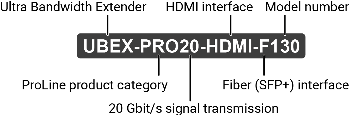
Lightware’s one of the most visionary development project is the UBEX (Ultra Bandwidth Extender) product family. UBEX is a fiber-optical, scaling AV-Over-IP system that allows uncompressed 4K UHD@60Hz 4:4:4 signal extension with latency-free multistreaming, designed to use in a 10G Ethernet network. UBEX operates with zero frame latency, provides seamless switching and lossless reproduction of source signals of up to 4K60Hz 4:4:4, without artifacts. Uncompressed 4K60Hz 4:4:4 data transmission, or visually lossless compression at higher data rates.
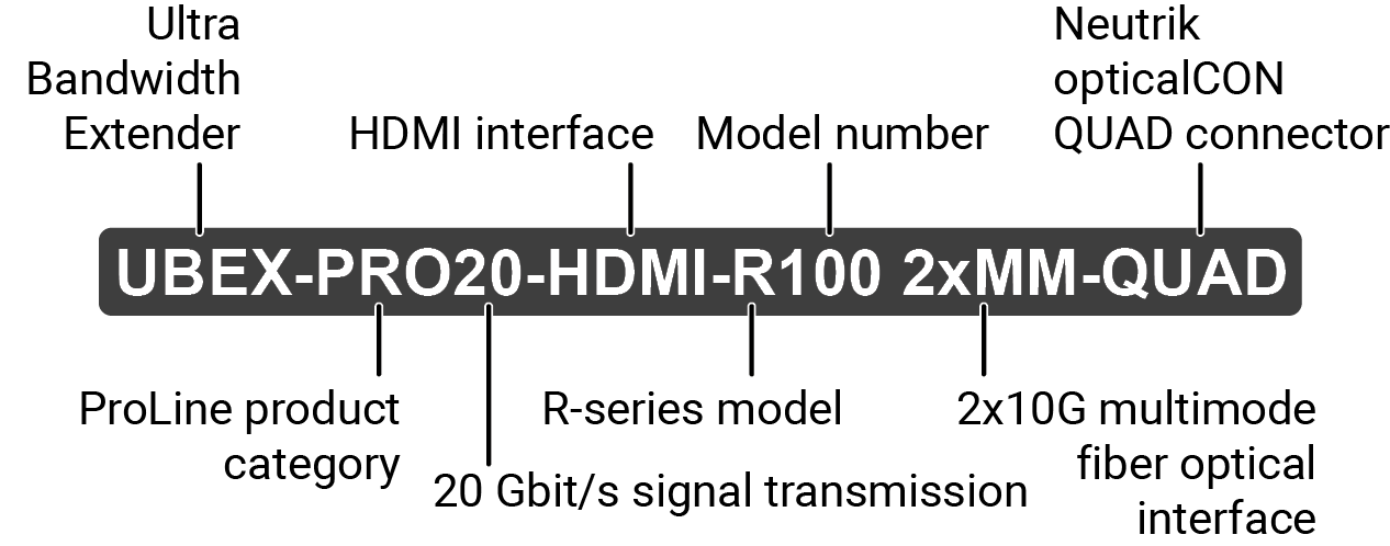
It has standard, 10 Gbps SFP+ optical modules installed, which are field exchangeable by the user. UBEX can transfer two video signals over a single 10G link with minimal compression, which requires half the router size compared to the needs of similar, 10G IP based architectures. With a 20G configuration, UBEX can transfer 4K@60Hz 4:4:4 over two links uncompressed. The maximum reachable distance is ranging between 400 m and 80 km, depending on the type of singlemode or multimode SFP+ optical modules installed in the device. The UBEX design also favors dual-screen applications, as a single UBEX device can handle 2x HDMI 2.0 video ports. For video signals that can be transferred within the 10G speed limit of a single optical fiber, a video signal redundancy feature is available employing the second optical fiber channel.
The R-type UBEX product variant is specifically designed to withstand the daily wear and tear impacts of dynamic, Rental&Staging type of applications. The devices share the features of the standard UBEX–PRO20–HDMI–F100 model, with additional features and changes in build and dimensions.
UBEX is available with numerous add-ons, providing audio breakaway signal management, K+M, IR, RS-232 and Gigabit Ethernet control.
The internal power source of UBEX has Medical (60601) and ITE (60950) grade classifications for maximum reliability.
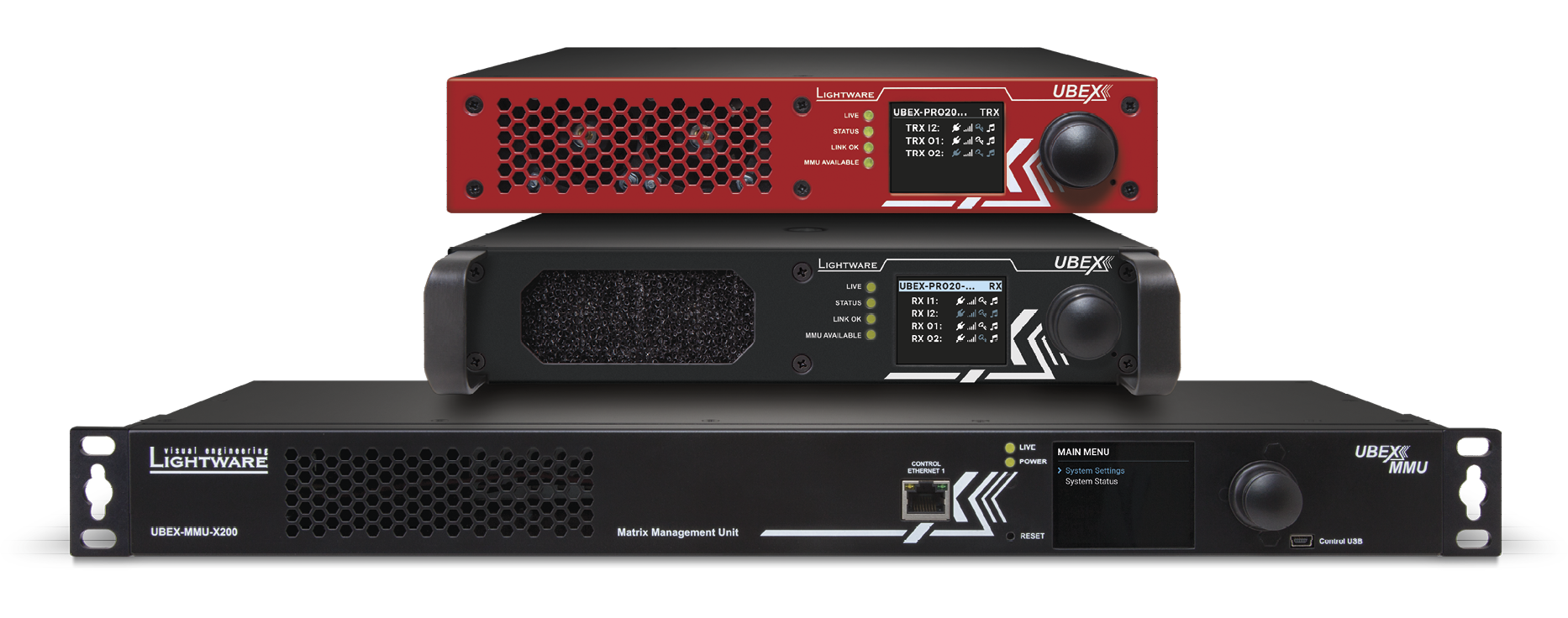
Matrix Management Unit
UBEX-MMU-X200 is a Matrix Management Unit (MMU) for the UBEX AV Over IP optical extender product line. With a standard Ethernet switch installed as a crosspoint, a virtual matrix can be created with UBEX devices connected to the IP network as input and output endpoints. The virtual matrix established requires to be managed and controlled by the MMU also connected to the Ethernet switch.
The MMU builds and constantly updates a database of the UBEX endpoints connected, displaying a traditional crosspoint view of the virtual matrix in the Lightware Device Controller (LDC) software, also displaying connected, but inactive units.
Users connect and communicate directly with the MMU in matrix mode, and MMU connects to and relays communication to the endpoint UBEX units.
The MMU displays information about endpoints and the overall virtual AV network, backup and restore functions are also provided to save and load the configuration. The MMU also manages the firmware updates of the connected endpoint UBEX devices, it is possible to initiate an update of the firmware on all UBEX units present in the network. Based on the communication with the UBEX endpoints, the MMU manages and supervises bandwidth use efficiency.
The Video Wall Wizard for UBEX features quick video wall installation with bezel adjustment and cropping, includes options for various layouts within the video wall matrix, and also allows zones for smart management.
Model Denomination
About the Serial Number
Lightware devices contain a label indicating the unique serial number of the product. The structure is the following:
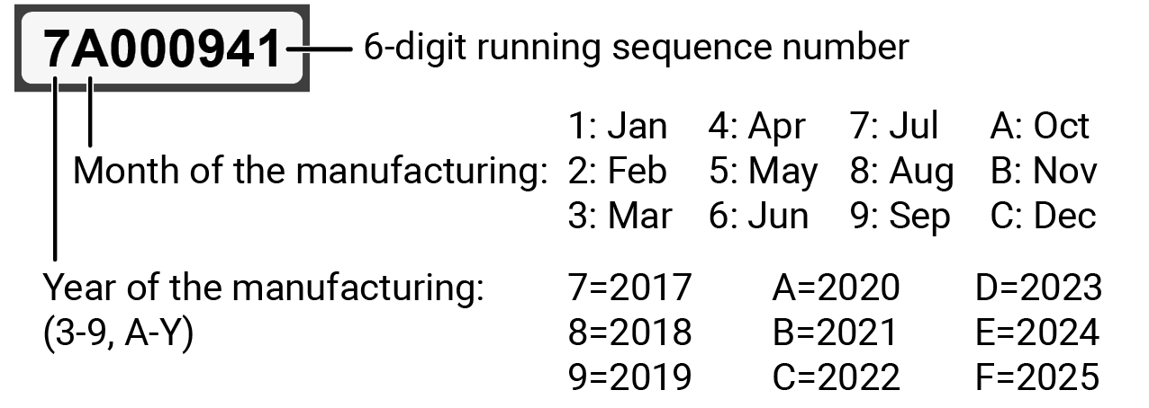
From 1st of October 2024, serial number format of Lightware devices is the following: the first two digits are of the year of manufacture, while the remaining digits make up the running sequence number.

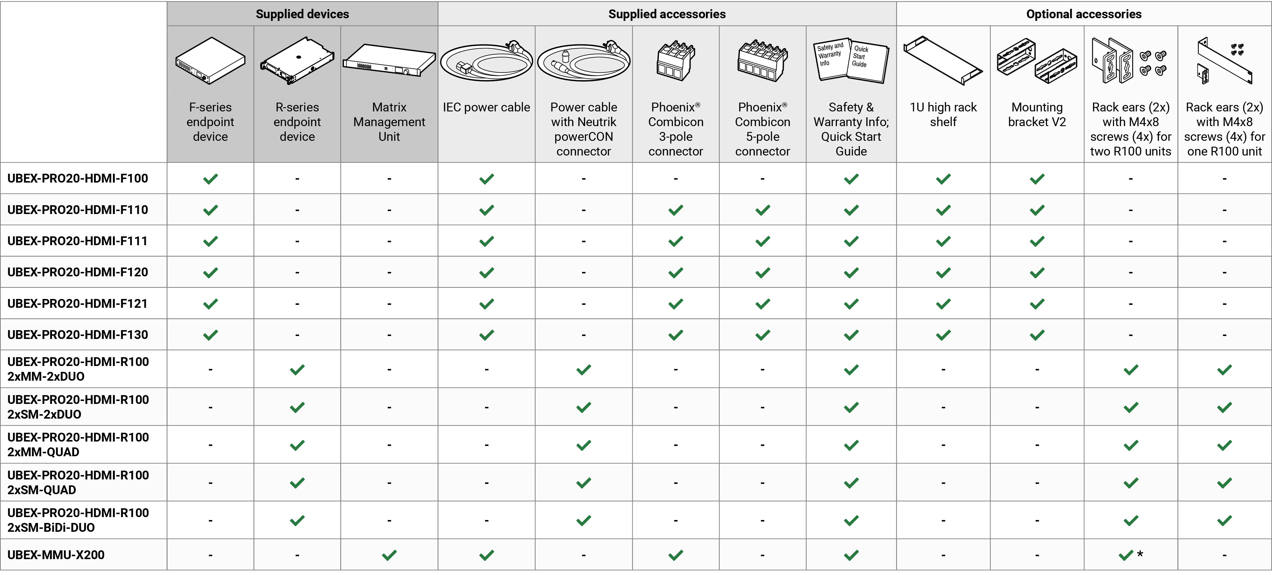
The following table describes all supplied and optional accessories of the UBEX endpoint devices by models. The optional (not-supplied) accessories can be purchased separately; please contact sales@lightware.com.
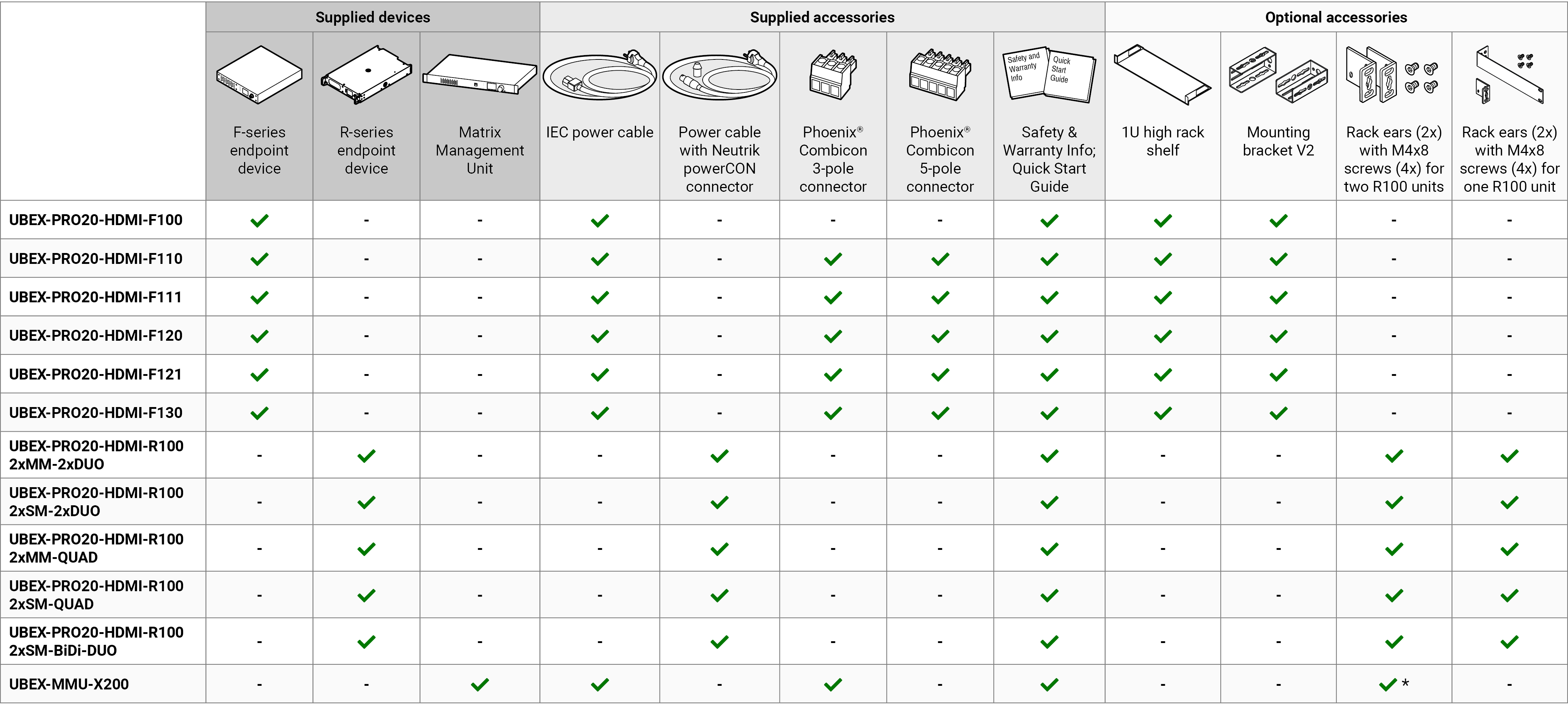
INFO:10GbE singlemode/multimode SFP+ modules and 10 GbE SFP+ to RJ45 modules can be ordered together and even separately for the F-series endpoint devices. Endpoint & SFP+ module packages are tested together. For the details, please contact sales@lightware.com.
* UBEX-MMU-X200 is shipped with 2 pcs rack ears pre-assembled to the chassis. Optionally 2 pcs additional rack ears can be ordered for the device.
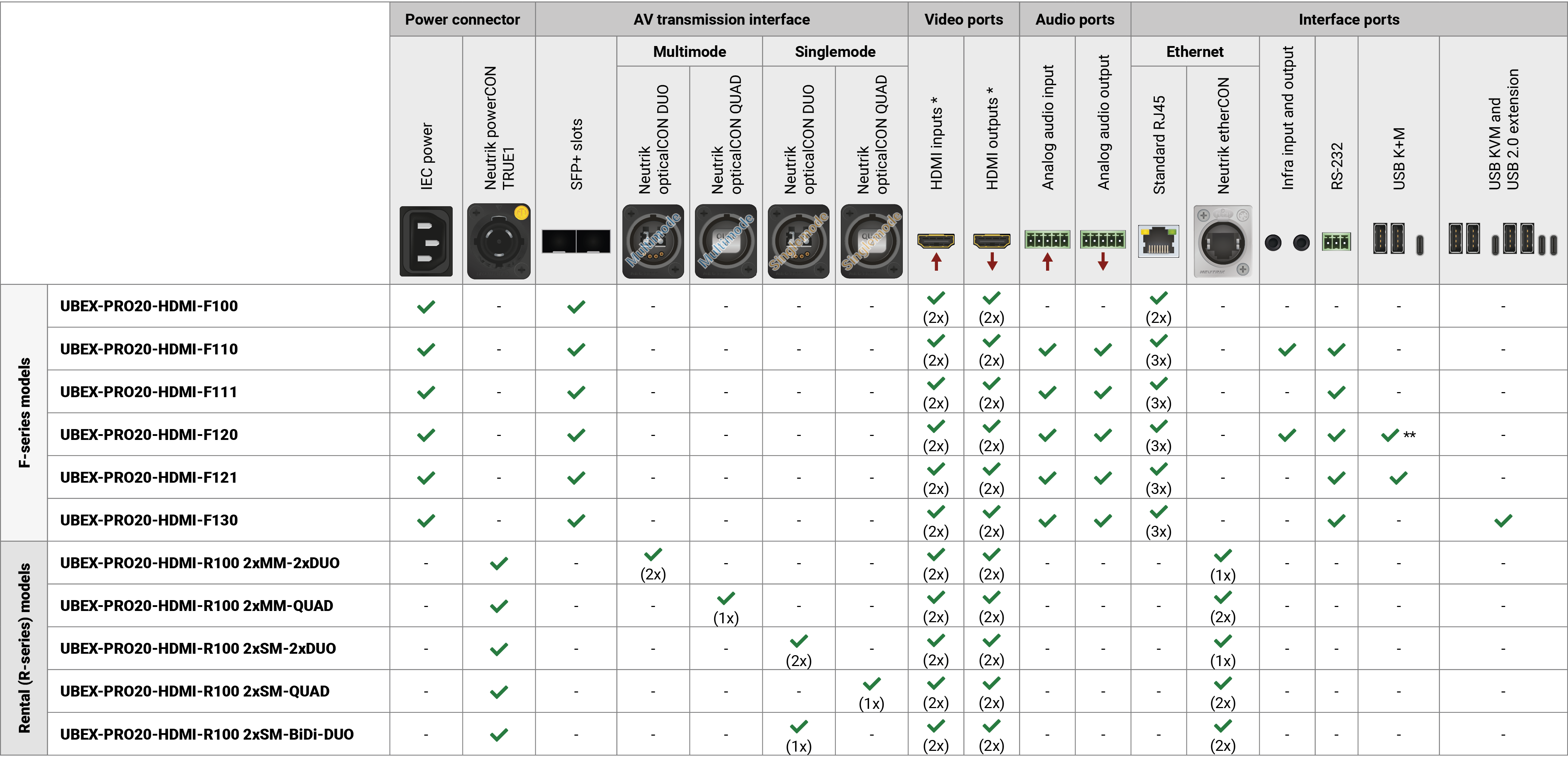
1.3. Endpoint Model Comparison
The available UBEX endpoint models have different features depending on their design. The following table contains the most important differences between the models:
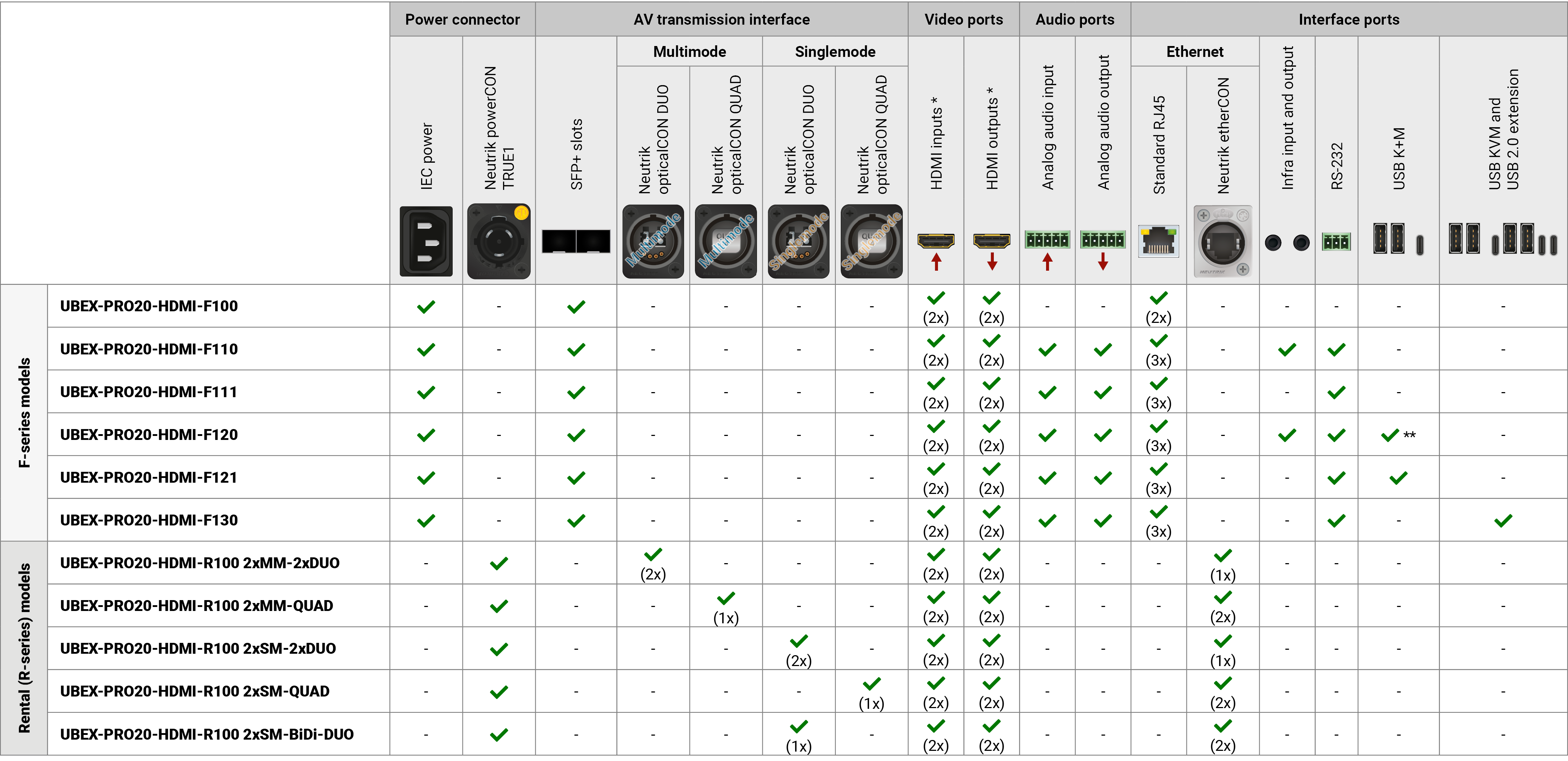
* The HDMI input and output ports of the R-series endpoint models have flange mounting option. ** UBEX-PRO20-HDMI-F120 variant contains USB-B connector instead of USB-C for the host interface.
For UBEX-MMU-X200

|
Dynamic Virtual Matrix |
|
The Matrix Management Unit (MMU) can build up a dynamic virtual matrix with any number of transmitters, receivers and transceivers connected in one network. It displays a traditional crosspoint view of the virtual matrix in the Lightware Device Controller (LDC) software, also displaying the video streams which can be sorted by unique tags for the easy recognition. |
|

|
Video Wall Application |
|
The UBEX devices can be arranged to a Video wall up to 8x4 (column x row) display devices. The displayed video can be the same on each display, one image enlarged to all the sinks, or the mixture of these. More different layout can be defined for the same video wall. |
|

|
Multiviewer |
|
The multiviewer operation mode of UBEX endpoints allows the extension of several streams to one single sink, where they can be variously ordered and grouped on a canvas. Multiviewer is a special operation mode like transmitter, receiver or transceiver, which can be activated in all UBEX endpoint models. |
|

|
Signal Bandwidth Management |
|
The Matrix Management Unit can prioritize the video streams by the signal bandwidth. The priority order is specified by the user based on the current application. |
|

|
Global Diagnostic Statistics |
|
The Matrix Management Unit collects data about the actual health and link status of all connected endpoint devices. User can always check the current state of the UBEX matrix in the Lightware Device Controller software or in the built-in web page of the MMU. |
|

|
Centralized Firmware Update |
|
The easiest way to keep your UBEX matrix up to date. The firmware package of all endpoint models are built in the MMU and the update procedure is executed automatically for the endpoints which are in the matrix. |
|

|
Expandable Matrix |
|
Get what you need. The UBEX matrix is starting from 16 endpoint devices and it can be expanded to 50, 100, 150 endpoints or unlimited by purchasing endpoint licenses for the MMU. |
|

|
Built-in Web Page |
|
Easy access from a web browser to control and configure the Matrix Management Unit and the UBEX matrix. |
For All UBEX Endpoint Models

|
Uncompressed 4K Support |
|
Up to HDMI 2.0 4K 2160p@60Hz 4:4:4 video input or 4096x2160@60Hz resolution over a 20 Gigabit network with extra low latency. |
|

|
Ethernet Based Extender |
|
The UBEX system is Ethernet based, using 10 GbE, IGMPv2, and IPv4 protocols. |
|
|
|
Pixel Accurate Reclocking |
|
Each output has a clean, jitter free signal, eliminating signal instability and distortion caused by long cables or connector reflections. |
|

|
Scaling the Output Image |
|
Video scaling is the process of changing the size of a video frame in order to match the native resolution of a display sink. It involves converting the resolution to a higher or lower format, and also a change in aspect ratio; typically from 4:3 to 16:9. |
|

|
HDCP 2.2 compliant |
|
The UBEX extenders comply to the HDCP 2.2 standard. HDCP capability on the digital video inputs can be disabled when non-protected content is extended. |
|

|
Frame Detector and Signal Analysis |
|
The exact video and audio signal format can be determined such as timing, frequencies, scan mode, HDCP encryption, color range, color space and audio sample rate. |
|

|
Changeable Operation Mode |
|
UBEX endpoint devices can be configured as transmitter, receiver, or transceiver in few simple steps by the user anytime. |
|

|
Multiviewer |
|
The multiviewer operation mode of UBEX endpoints allows the extension of several streams to one single sink, where they can be variously ordered and grouped on a canvas. Multiviewer is a special operation mode like transmitter, receiver or transceiver, which can be activated in all UBEX endpoint models. |
|

|
Seamless Switching (Clean Cut) |
|
UBEX series extenders provide seamless switching (clean cut) technology, which is the capability to deliver consistent performance and reliability. The advantage of the technology is that various environments with different video sources and displays will not impact signal loss. |
|

|
Multi Stream |
|
UBEX endpoint devices are able to simultaneously transmit two video streams with embedded audio via the SFP+ interface. |
|

|
Stream Copy |
|
UBEX endpoint devices are able to copy the stream of the HDMI out 1 to the HDMI out 2 port. This is the COPY function. The function is available in receiver and transceiver operation modes. |
|

|
Color Space Conversion |
|
Color space of the output video can be changed based on the type of the display device. |
|

|
Deep Color Support |
|
It is possible to transmit the highest quality 36-bit video streams and HDR contents for the perfect color reproduction. |
|

|
Custom Resolutions |
|
Endpoint devices support any type of display device with custom resolutions to best fit the user's application. |
|

|
Wide Range of Audio Format Support |
|
Endpoint devices support the most of known audio signal formats, including HBR audio like Dolby TrueHD, Dolby Atmos and DTS-HD Master Audio 7.1. |
|

|
Local Video Output |
|
User can attach a local monitor to observe the video signal sent through the SFP+ ports. The resolution and clock frequency are the same with the HDMI inputs, no internal scaling or conversion is applied. The function is available in transmitter and transceiver operation modes. |
|

|
Local Video Input |
|
User can attach local source devices to the input ports of the UBEX receiver. The streams with the received resolution and clock frequency are transmitted on the output ports and no internal scaling or color conversion is applied. The function is available in receiver operation mode. |
|

|
Modular SFP+ Interface |
|
UBEX series extenders use standard, certificated 10 Gbps SFP+ optical modules, which are plug and play, so they are swappable by the user. |
|

|
Silent Operation |
|
The optimized fan operation allows installing the endpoint device to places where minimum sound emission is required. |
|

|
Dark Mode |
|
Rental application requires this function, which keeps the LCD screen and the LEDs unlit to hide the device during the event. |
|

|
Open API |
|
Open-source API technology at the core makes these Lightware products easy to integrate into third-party systems. Every bit of data in Lightware systems is openly available for higher level management and monitoring systems. |
Only for UBEX-PRO20-HDMI-F110, -F111, -F120, -F121 and -F130 Models

|
Audio Embedder and De-embedder Function |
|
The analog audio can be embedded to HDMI outputs and embedded audio can be routed to the analog audio output in transmitter, receiver, and transceiver operation modes as well. |
|

|
RS-232 Interface |
|
AV systems can also contain serial port for controlled devices. Serial port supports any unit that works with standard RS-232. |
Only for UBEX-PRO20-HDMI-F110 and -F120 Models

|
Infrared Interface |
|
Infrared (IR) is a wireless technology used for device communication over short ranges. Infrared is commonly used for remote control based applications. Third-party control systems may send IR control commands to endpoints, turning them on and off or switching their inputs. |
Only for UBEX-PRO20-HDMI-F120 and -F121 Models

|
USB K+M Extension |
|
K+M extension for USB HID (Human Interface Devices, e.g. keyboard, mouse, presenter). |
Only for UBEX-PRO20-HDMI-F130 Model
|
|
USB KVM and USB 2.0 Extension Powered by Icron |
|
KVM extension with USB 2.0 support for USB HID (Human Interface Devices, e.g. keyboard, mouse, presenter, webcam, etc). |
Only for the UBEX-PRO20-HDMI-R100 Series Models

|
Mounting Threads |
|
Mounting threads on top and one side for the R-series models to conform strict installation safety regulations. |
UBEX extender system has two main application modes: #applicationmode
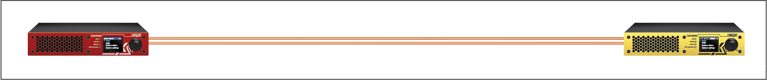
▪Extender Mode - Point-to-point connection between a transmitter and a receiver, or between two transceiver endpoint devices. The user manual of the UBEX Extender mode can be downloaded from the following link: #extendermode
https://go.lightware.com/ubex-extender-pum
▪Matrix Mode - Virtual AV matrix with more transmitters, receivers, transceivers, and a Matrix Management Unit (MMU) that controls the AV network. This document is about the Matrix mode only. #matrixmode
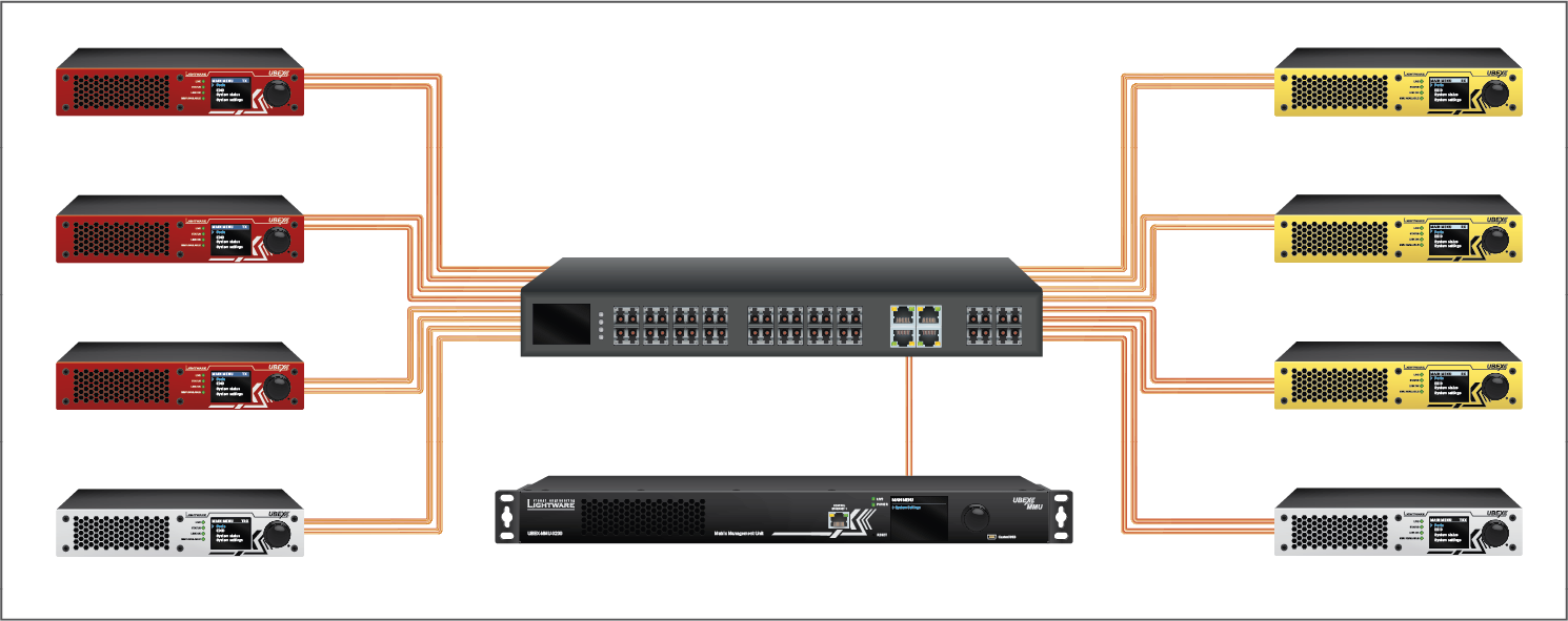
INFO:The Extender or Matrix mode is set automatically in the endpoint device. If the device detects direct connection with another endpoint device at the other side of the connection, the mode is set to Extender mode; if the MMU connects to the device, the mode is set to Matrix mode.
The two modes bring different functionality and control methods for the endpoint and the MMU devices. The following settings are available in the MMU only in case the Matrix mode:
▪Operation mode setting (TX / RX / TRX / RXMV configuration for the endpoints)
▪All network-related settings, e.g. DHCP setting, static IP address, etc.
▪All HDMI port settings for the inputs and outputs
▪EDID settings
▪Reloading factory defaults
▪Centralized firmware update method for the endpoint devices
ATTENTION!Switching between the Extender and Matrix mode changes the LCD menu structure and the LW3 command protocol tree of the endpoint device. It happens because of the control settings listed above transfer between the endpoints and the MMU.
1.6. Typical Applications
1.6.1. System Design Studio
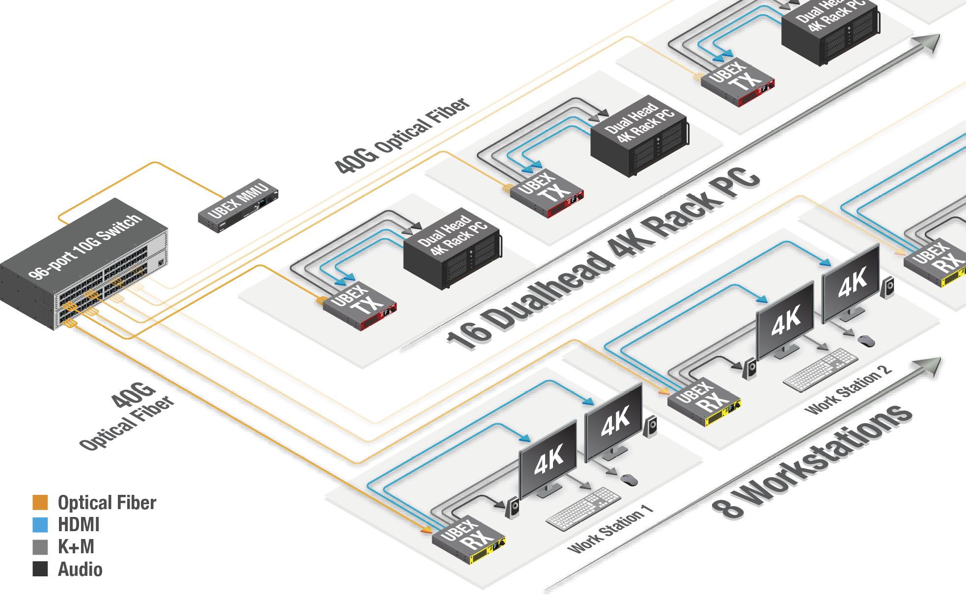
Application diagram of Matrix mode - System design studio
Description
The UBEX matrix has 16 pcs transmitters (UBEX-PRO20-HDMI-F121, TX mode) and 8 pcs receivers (UBEX-PRO20-HDMI-F121, RX mode).
Each transmitter is connected to a dual head 4K rack PC and transmits two streams together. The transmitted HDMI streams can be a 4K UHD 60 Hz 4:4:4 and a 4K UHD 30 Hz 4:4:4, or two 4K 60 Hz 4:2:2. The transmitters receive an analog audio signal as well, it is also transmitted beside the HDMI streams and can be selected to any or all ports of the receivers.
Each receiver has two 4K-ready video sink devices and a symmetrical analog audio sink device.
The matrix is supervised by the UBEX Matrix Management Unit (MMU) which is controlled by a PC. All endpoint devices and the MMU are connected to a 96-port 10G Layer 3 network switch.
Endpoint License
This configuration requires UBEX-MMU-X200-50 license which makes available to claim up to 50 endpoint devices.
1.6.2. Corporate Application
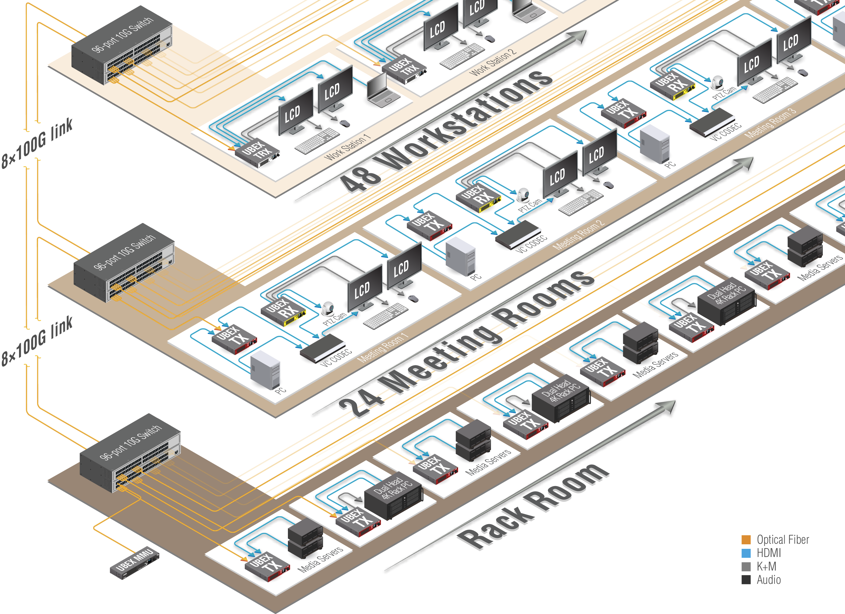
Application diagram of Matrix mode - Corporate application
Description
The UBEX matrix has more UBEX-PRO20-HDMI-F121 endpoint devices which can be in transmitter, receiver, or transceiver operation modes.
The matrix is supervised by the UBEX Matrix Management Unit (MMU) which is controlled by a PC. All endpoint devices and the MMU are connected to three stacked 96-port 10G Layer 3 network switches.
The transmitters can be connected to a single laptop or a dual head 4K rack PC and transmitting two streams together.
The receivers can be connected to one or two sink devices belongs to the required application.
The transceivers can be connected to a source and a sink device together. The source stream is extended to another transceiver or receiver, the destination stream which is received from another UBEX extender is displayed on the sink device.
The transmitted HDMI streams can be a 4K UHD 60 Hz 4:4:4 and a 4K UHD 30 Hz 4:4:4, or two 4K 60 Hz 4:2:2 in the case of the transmitters.
Thanks to the 20G full-duplex SFP+ interface the transceiver has no bandwidth limitation on the input and output sides either. The transceivers are able to receive and transmit 2x 4K60 Hz 4:4:4 24 bit streams.
Endpoint License
This configuration requires UBEX-MMU-X200-150 license which makes available to claim up to 150 endpoint devices.
1.6.3. Video Wall Application
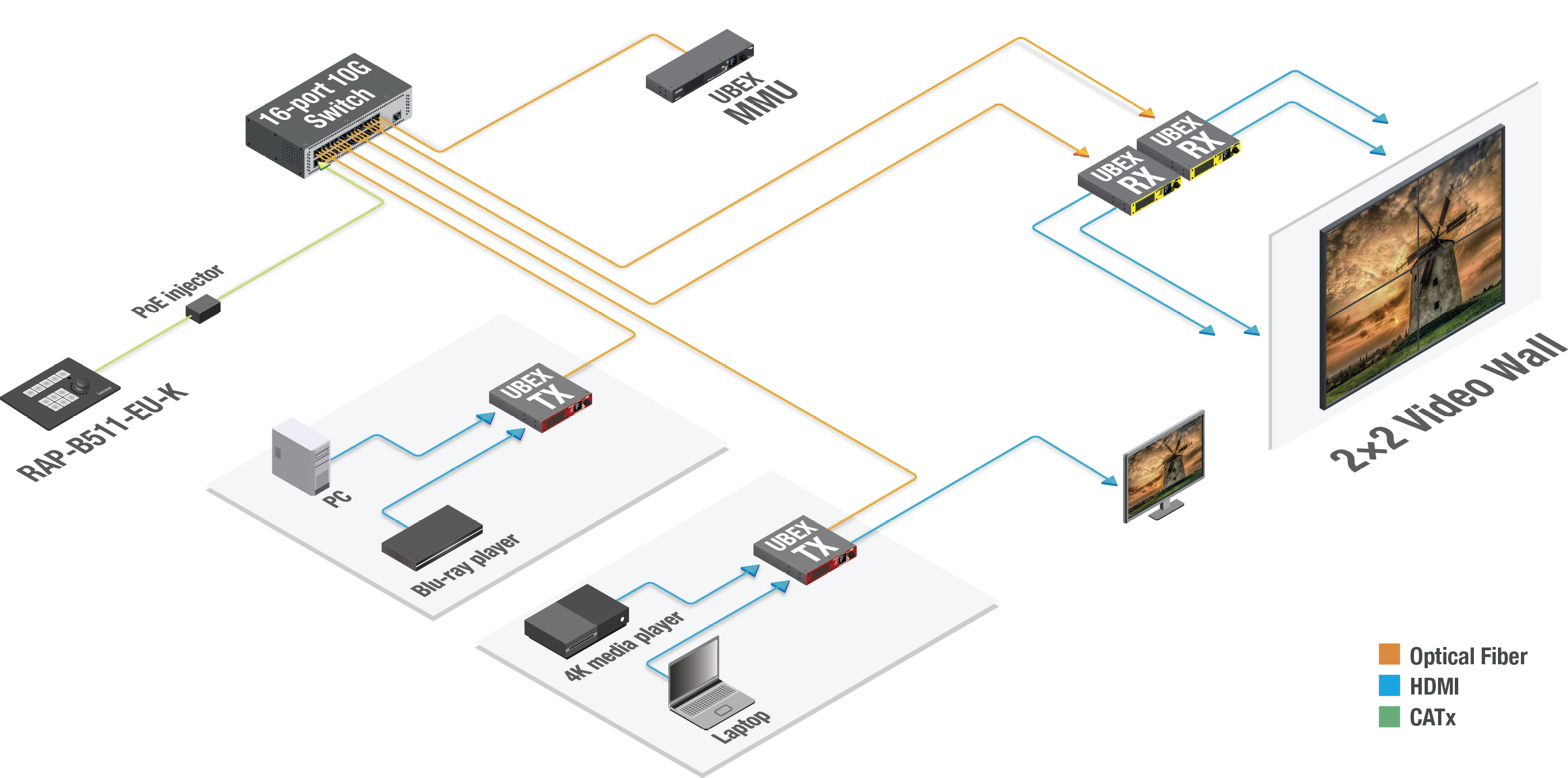
Application diagram of Matrix mode - Video wall application
Description
The UBEX matrix contains two transmitters and two receivers (UBEX-PRO20-HDMI-F100 endpoint models).
The matrix is supervised by the UBEX Matrix Management Unit (MMU) which is controlled by a PC. All endpoint devices and the MMU are connected to a 16-port 10G Layer 3 network switch.
Two receivers are connected to four wall-mounted displays in a 2x2 video wall application. The source streams are from four different source devices (PC, Blu-ray player, 4K media player, and laptop) and transmitted by the two UBEX transmitters.
The video wall may have more different layouts and a layout may be divided into more zones. See more details about video wall feature in the Video Wall section.
The UBEX matrix is controlled by a RAP-B511-EU-K room automation panel which can send LW3 protocol commands to the MMU over Ethernet. The control buttons of the RAP panel can be programmed for the best available supervising of the video wall, for example changing the layout of the wall, or crosspoint changing for each zones, etc.
INFO:RAP-B511 series devices can be ordered separately for the UBEX matrix. For the details please contact sales@lightware.com.
Endpoint License
This configuration does not require endpoint license. The MMU is limited to claim up to 16 endpoint devices.
1.6.4. Live Event with Dual Scaler Application
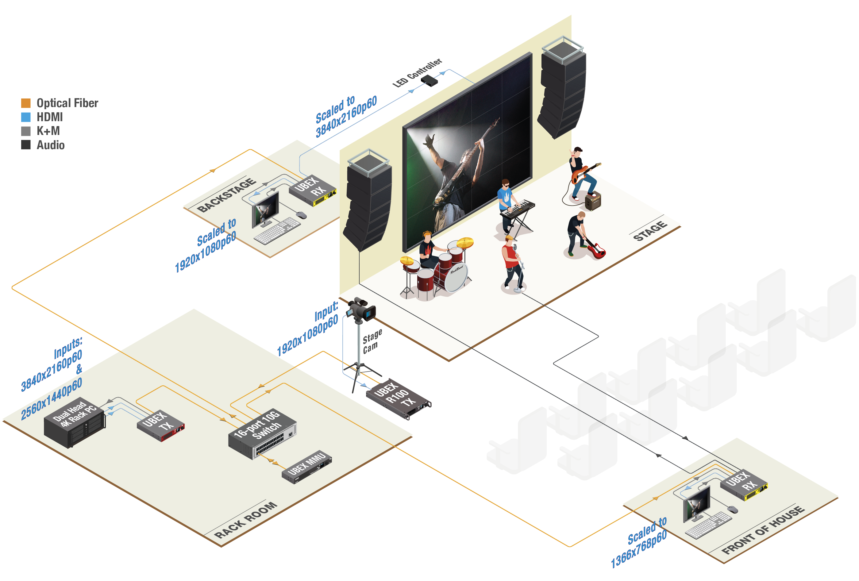
Application diagram of Matrix mode - Live event application
Description
This UBEX matrix has two transmitters (a UBEX-PRO20-HDMI-F121 and a UBEX-PRO20-HDMI-R100 models) and two receivers (UBEX-PRO20-HDMI-F121 models) which are connected to a 16-port 10G managed network switch and supervised by the UBEX-MMU-X200 Matrix Management Unit.
The sources are a dual head 4K PC in the rack room which provides two streams (3840x2160p60 and 2560x1440p60) and a stage camera which provides an 1080p stream from the field.
The stream of the stage camera is transmitted to the LED wall behind the band in 4K60 resolution and the same stream can be seen in the backstage on a 1080p monitor. Both of them are coming from the two output ports of the UBEX receiver.
The video wall may have more different layouts and a layout may be divided into more zones. See more details about video wall feature in the Video Wall section.
The audio of the concert is provided by the UBEX receiver in the front of house: the analog audio output transmits the audio stream for the active speakers and the singer's microphone is plugged to the analog audio input port.
The show can be supervised and controlled from the front of house and the backstage either thanks to the USB K+M extension of the UBEX enpoint devices.
Endpoint License
This configuration does not require endpoint license. The MMU is limited to claim up to 16 endpoint devices.
1.6.5. Flight Simulation Application
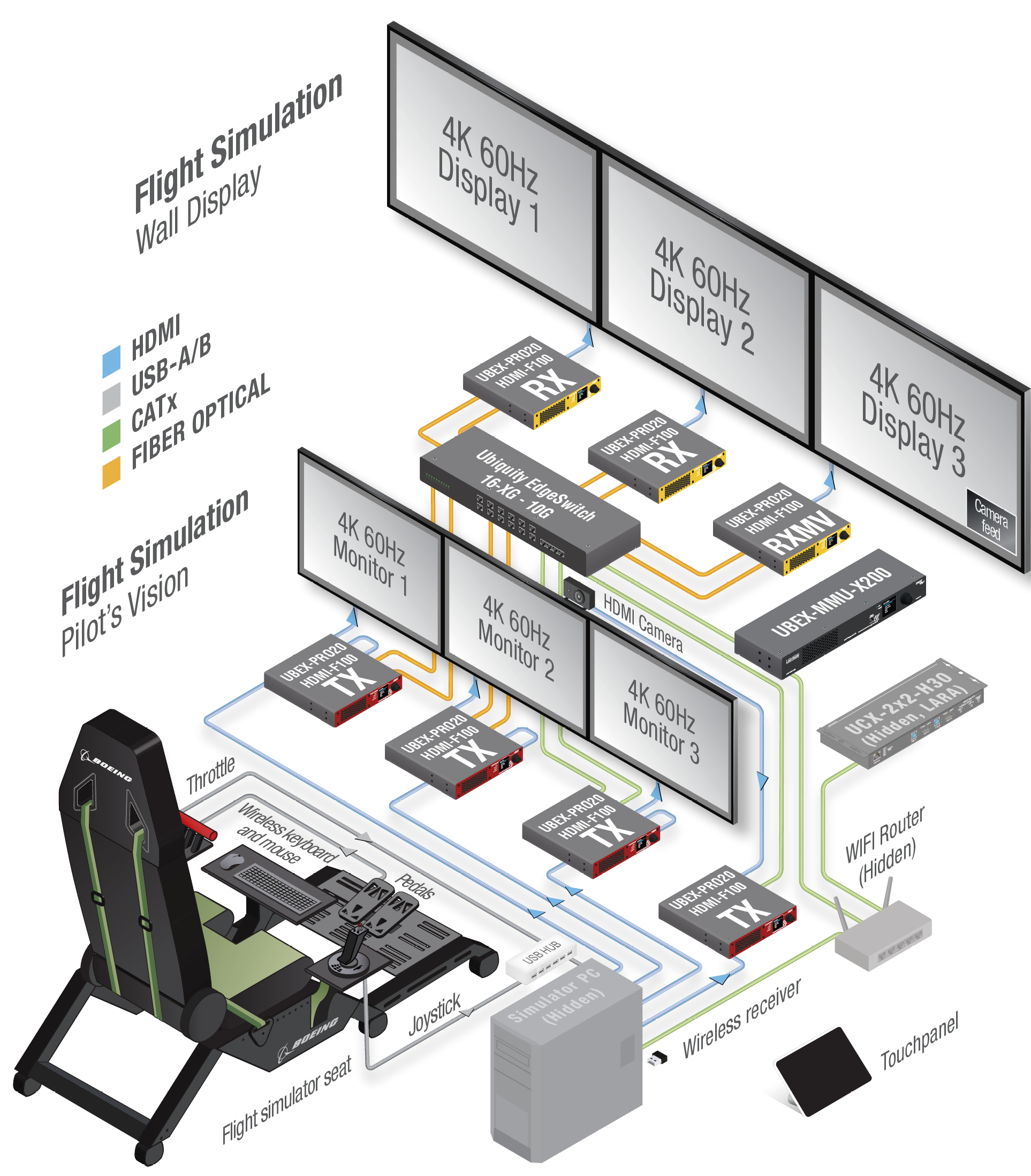
Description
INFO:This application appeared live at the Integrated System Europe (ISE) 2023 exhibition in Barcelona, Spain.
The UBEX matrix contains four transmitters and three receivers (all of them are UBEX-PRO20-HDMI-F100 endpoint models). A UCX-2x2-H40 Taurus extender is also the part of the system running a LARA room automation software in the background.
The matrix is supervised by the UBEX Matrix Management Unit (MMU) which is controlled by a PC. All endpoint devices and the MMU are connected to a 16-port 10G Layer 3 network switch.
The source device of three transmitters is the Simulator PC running the Microsoft Flight Simulator software, the fourth transmitter is connected to a webcamera recording the pilot. The lower row of the 4K monitors are the pilot's displays and the streams are comming from the local HDMI output ports of the transmitters. The upper row of the 4K displays are for the total view of the pilot's vision.
The stream of the webcamera is appears in picture-in-picture mode in the lower right corner of a 4K display and uses the multiviewer feature of the UBEX extenders. See more details about it in the Multiviewer Mode section.
This configuration does not require endpoint license. The MMU is limited to claim up to 16 endpoint devices.
1.6.6. Multiviewer Application
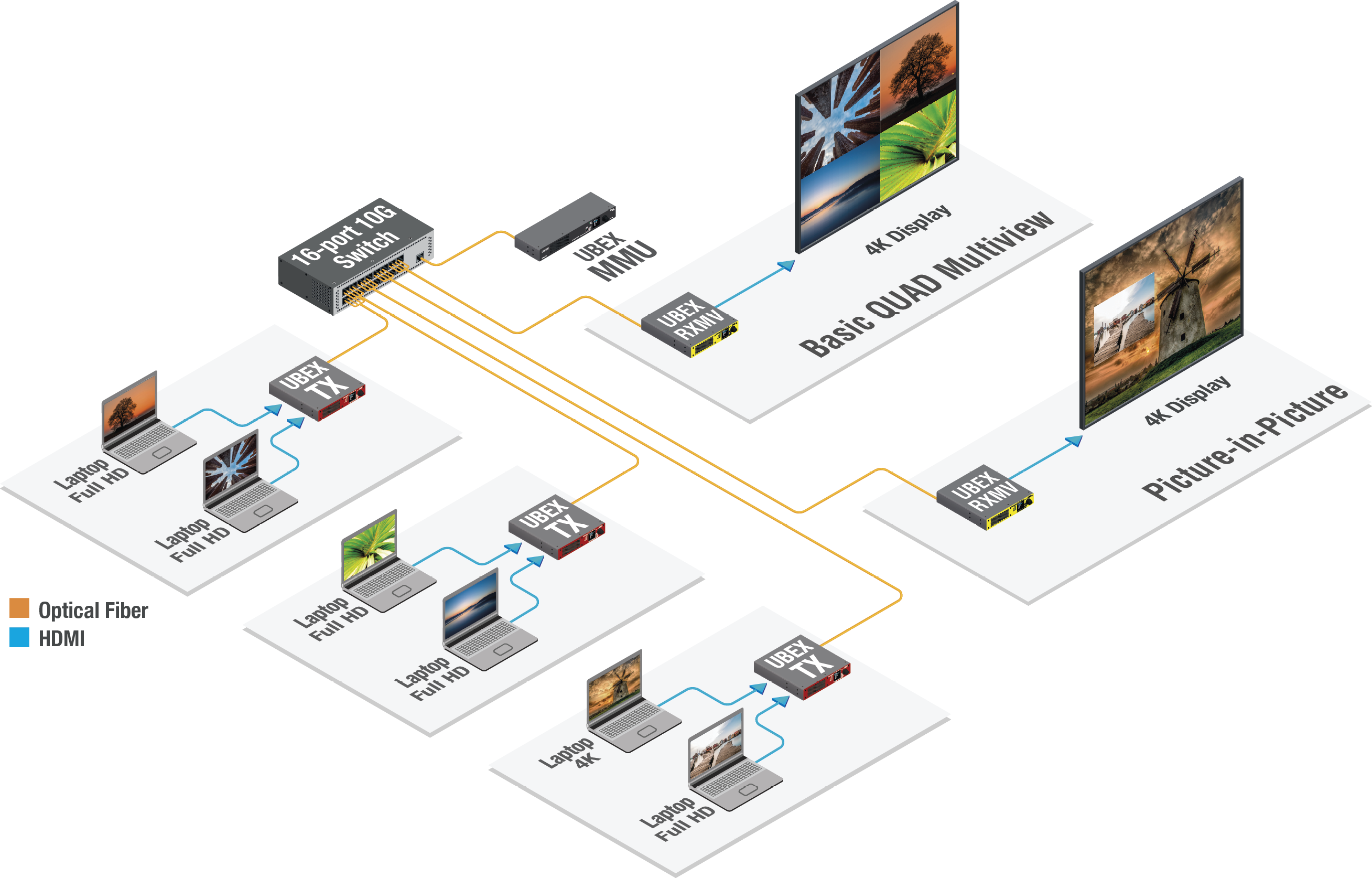
Application diagram of Matrix mode - Multiviewer application
Description
This matrix is built for two multiviewer sinks: a basic QUAD multiview and a picture-in-picture display. The source side has six laptops connected to three UBEX-PRO20-HDMI-F100 transmitters (TX); the sink side has two 4K displays connected to the two UBEX-PRO20-HDMI-F100 multiviewers (RXMV).
A multiviewer device can handle up to five different streams. Up to four streams can be ordered to various multiview layouts displayed on one sink device; and one stream can be displayed on another sink device. See more details in the Multiviewer Mode section and find a step-by-step tutorial in the Multiview Designer - Tutorial section.
Endpoint License
This configuration does not require endpoint license. The MMU is limited to claim up to 16 endpoint devices.
1.7. Availability of the Endpoint Models
The following table shows the production life cycle status of the UBEX endpoint models.
|
Model |
Status |
Equivalent Active Model |
|---|---|---|
|
UBEX-PRO20-HDMI-F100 |
Active |
- |
|
UBEX-PRO20-HDMI-F110 |
Will be discontinued |
UBEX-PRO20-HDMI-F111 |
|
UBEX-PRO20-HDMI-F111 |
Active |
- |
|
UBEX-PRO20-HDMI-F120 |
Will be discontinued |
UBEX-PRO20-HDMI-F121 |
|
UBEX-PRO20-HDMI-F121 |
Active |
- |
|
UBEX-PRO20-HDMI-F130 |
Active |
- |
|
UBEX-PRO20-HDMI-R100 2xMM-2xDUO |
Active |
- |
|
UBEX-PRO20-HDMI-R100 2xMM-QUAD |
Active |
- |
|
UBEX-PRO20-HDMI-R100 2xSM-2xDUO |
Active |
- |
|
UBEX-PRO20-HDMI-R100 2xSM-QUAD |
Active |
- |
|
UBEX-PRO20-HDMI-R100 2xSM-BiDi-DUO |
Active |
- |
See the differences about the UBEX endpoint variants in the Endpoint Model Comparison section.
The following sections are about the physical structure of the device, input/ output ports and connectors; software and hardware capabilities:
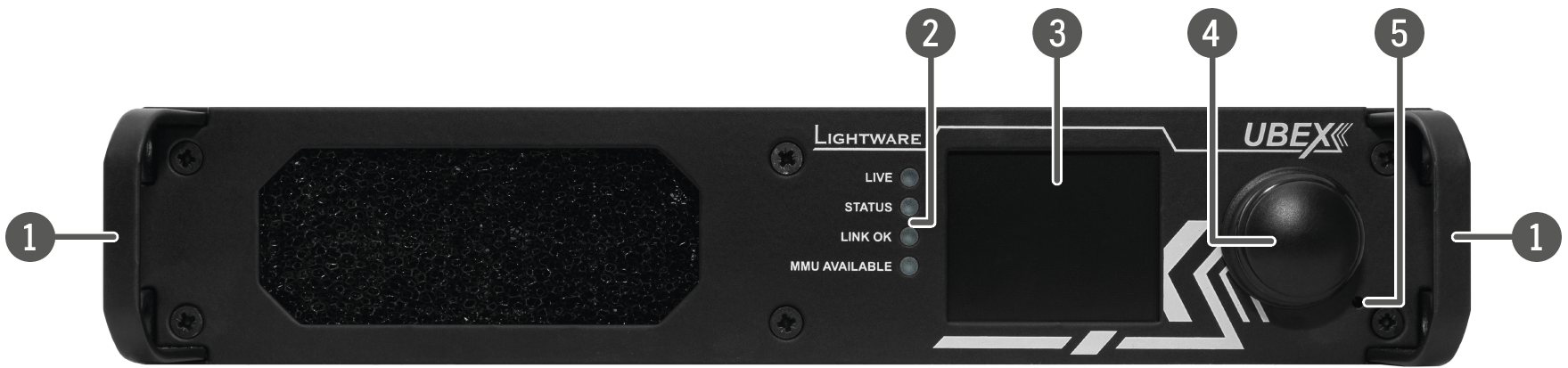
2.1. Front and Rear View - F-series Endpoint Devices
All Models
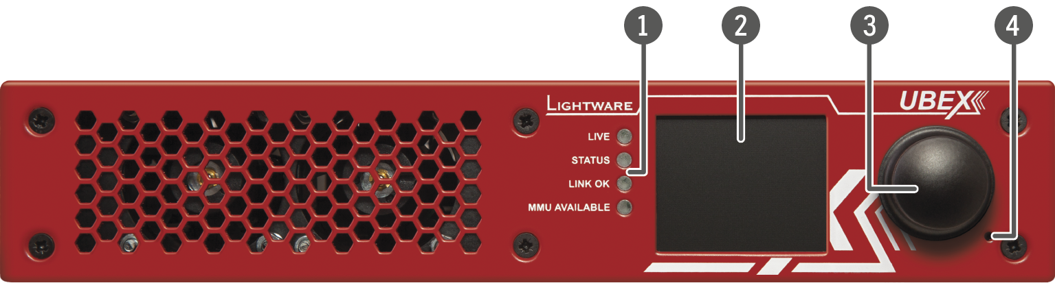
|
|
Status LEDs |
The LEDs give immediate feedback about the current status of the endpoint device. See the details about the operation of the LEDs in the Status LEDs section (on the right side). |
|
|
LCD screen |
LCD screen showing the most important settings and parameters in the front panel menu. The available settings and information depends on the current application mode. See the details in the Front Panel LCD Menu Operation - Endpoints chapter. |
|
|
Jog dial control knob |
Easy setting and menu navigation by the jog dial control. Keep dialing and clicking while getting feedback on the LCD. The operation of the jog dial control knob can be disabled by the control lock feature. The function can be enabled using the following methods: ▪Lightware Device Controller (LDC) software / Built-in website - see the details in the Health Status Tab section; ▪LW3 protocol command - see the details in the Control Lock section. |
|
|
Reset button |
Reboots the device (the same as disconnecting from the power source and reconnecting again). |


|
LIVE |
Transmitter / Receiver / Transceiver |
||

|
blinking |
The device is powered and ready to use. |
|

|
off |
The device is not powered or out of operation. |
|
|
STATUS |
Transmitter / Receiver / Transceiver |
||

|
on |
All measured temperature and voltage values are within the limits. |
|

|
blinking |
Measured temperature or voltage value is out of the limits. |
|
|
|
off |
The device is not powered or out of operation. |
|
|
LINK OK |
Transmitter / Receiver / Transceiver |
||

|
on |
The connection is established on the fiber optical links and the Link Aggregation is working. |
|

|
blinking |
The connection is established on the fiber optical links and LACP detection period is active. |
|
|
|
off |
No connection is established on one of the fiber optical links. |
|
|
MMU AVAILABLE |
Transmitter / Receiver / Transceiver |
||

|
on |
Matrix mode is active; the communication is live between the endpoint and the Matrix Management Unit (MMU). |
|
|
|
blinking |
Matrix mode is active; no communication between the endpoint and the MMU. |
|
|
|
off |
Extender mode is active; no communication between the endpoint and the MMU. |
|
Dark Mode
Rental application requires this function, which keeps the LCD screen and the LEDs unlit to hide the device during the event. The function can be enabled via the following methods:
▪Front panel LCD menu - see the details in the Front Panel section;
▪Lightware Device Controller (LDC) software / Built-in website - see the details in the Health Status Tab section;
▪LW3 protocol command - see the details in the Dark Mode Setting section.
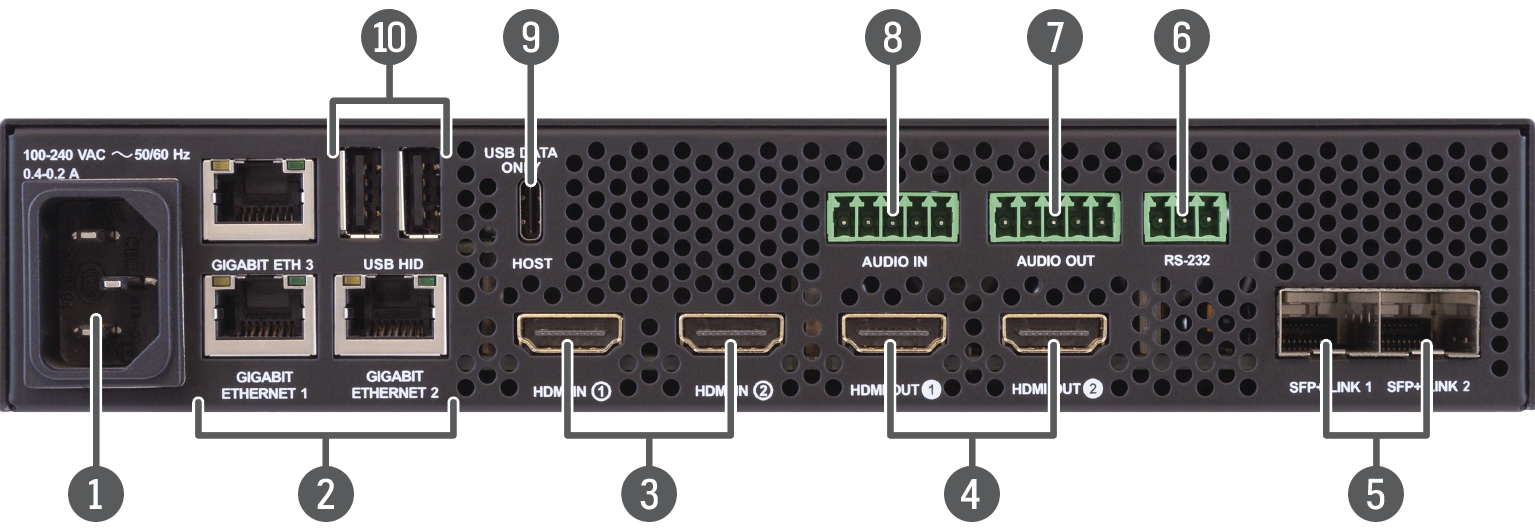
2.1.2. Rear View - F100 / F111 / F121 Models
UBEX-PRO20-HDMI-F100
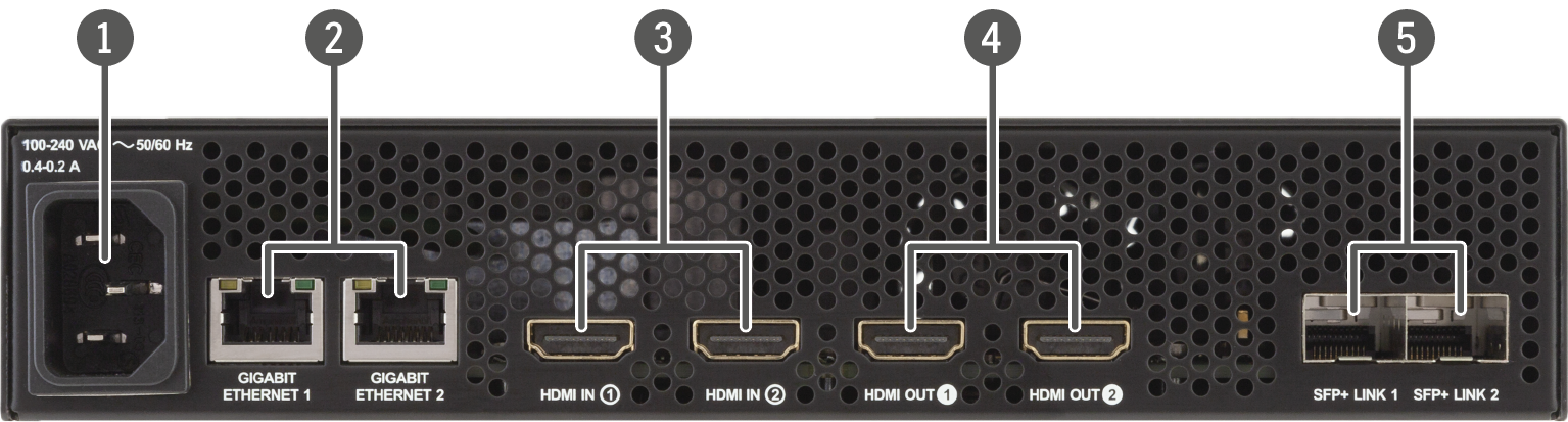
UBEX-PRO20-HDMI-F111
UBEX-PRO20-HDMI-F121
|
|
AC connector |
Standard IEC connector accepting 100-240 V, 50 or 60 Hz. See more details about it in the AC Power Connection section. |
|
|
Ethernet connectors |
Standard locking RJ45 connectors for 1 Gbps Ethernet connections to control the device, for user Ethernet access, and firmware update purpose. See the details about the cable wiring in the Ethernet Connectors section and the concept of the operation in the Ethernet Interface section. |
|
|
HDMI input ports |
HDMI input ports with HDMI 2.0 support for the source devices. When the device is configured as a receiver, the ports operate as local HDMI inputs. The HDMI in 1 port cannot accept AV signal when the device is configured as transceiver. See more details about the HDMI interface in the Video Interface section. |
|
|
HDMI output ports |
HDMI output ports with HDMI 2.0 support for sink devices. When the device is configured as transmitter, the both ports operate as local HDMI outputs. When the device is configured as transceiver, the HDMI out 2 port operates as a local HDMI output. The HDMI out 2 port is able to copy the signal of the HDMI in 1 port when the device is configured as receiver or transceiver. See more details about the HDMI interface in the Video Interface section. |
|
|
SFP+ port slots |
Optical port slots for 2x 10 GbE SFP+ modules or 2x 10 GbE DAC cables. Ports can be used for either singlemode or multimode fiber optical connections. See more details about the SFP+ interface in the SFP / SFP+ Interfaces section. |
|
|
RS-232 connector |
3-pole Phoenix connector for serial communication. See more details about the pin assignment in the RS-232 Connector section, about the cable wiring in the Serial Ports section, and the concept of the operation in the Serial Interface section. |
|
|
Analog audio output port |
5-pole Phoenix connector for balanced analog audio output. The port is available in all operation modes (TX/RX/TRX). See more details about the pin assignment in the Symmetrical Analog Stereo Audio Connector section, about the cable wiring in the Audio Ports section, and about the analog audio interface in the Audio Interface section. |
|
|
Analog audio input port |
5-pole Phoenix connector for balanced analog audio input. The port is available in all operation modes (TX/RX/TRX). See more details about the pin assignment in the Symmetrical Analog Stereo Audio Connector section, about the cable wiring in the Audio Ports section, and about the analog audio interface in the Audio Interface section. |
|
|
Host port |
USB-C connection between the extender and the host computer. The port receives USB data only, no AV signal transmission is accepted. It supports USB 2.0 standard only. See more details about the K+M feature in the USB K+M Interface (F120 / F121 Models) section. |
|
|
USB HID ports |
Two USB-A ports for HID-compatible devices (preferably keyboard and mouse). The signal is transmitted to the receiver over the SFP+ interface. See more details about the KVM feature in the USB K+M Interface (F120 / F121 Models) section. |


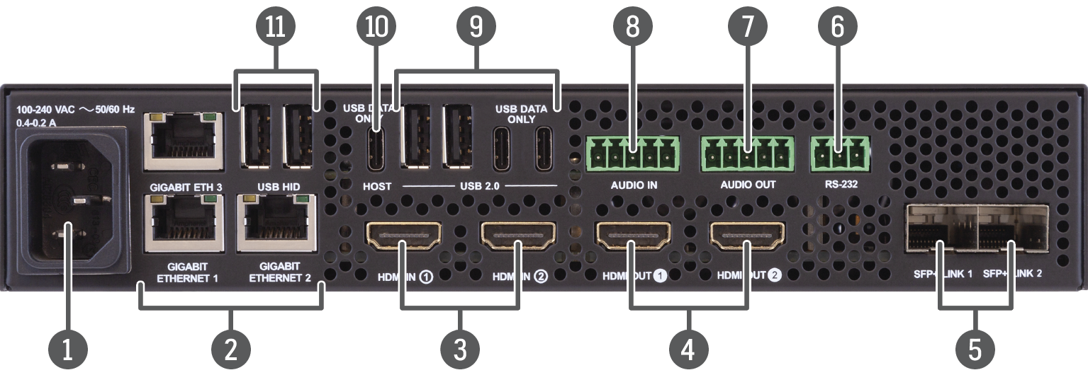
2.1.3. Rear View - F130 Model
UBEX-PRO20-HDMI-F130
|
|
AC connector |
Standard IEC connector accepting 100-240 V, 50 or 60 Hz. See more details about it in the AC Power Connection section. |
|
|
Ethernet connectors |
Standard locking RJ45 connectors for 1 Gbps Ethernet connections to control the device, for user Ethernet access, and firmware update purpose. See the details about the cable wiring in the Ethernet Connectors section and the concept of the operation in the Ethernet Interface section. |
|
|
HDMI input ports |
HDMI input ports with HDMI 2.0 support for the source devices. When the device is configured as a receiver, the ports operate as local HDMI inputs. The HDMI in 1 port cannot accept AV signal when the device is configured as transceiver. See more details about the HDMI interface in the Video Interface section. |
|
|
HDMI output ports |
HDMI output ports with HDMI 2.0 support for sink devices. When the device is configured as transmitter, the both ports operate as local HDMI outputs. When the device is configured as transceiver, the HDMI out 2 port operates as a local HDMI output. The HDMI out 2 port is able to copy the signal of the HDMI in 1 port when the device is configured as receiver or transceiver. See more details about the HDMI interface in the Video Interface section. |
|
|
SFP+ port slots |
Optical port slots for 2x 10 GbE SFP+ modules or 2x 10 GbE DAC cables. Ports can be used for either singlemode or multimode fiber optical connections. See more details about the SFP+ interface in the SFP / SFP+ Interfaces section. |
|
|
RS-232 connector |
3-pole Phoenix connector for serial communication. See more details about the pin assignment in the RS-232 Connector section, about the cable wiring in the Serial Ports section, and the concept of the operation in the Serial Interface section. |
|
|
Analog audio output port |
5-pole Phoenix connector for balanced analog audio output. The port is available in all operation modes (TX/RX/TRX). See more details about the pin assignment in the Symmetrical Analog Stereo Audio Connector section, about the cable wiring in the Audio Ports section, and about the analog audio interface in the Audio Interface section. |
|
|
Analog audio input port |
5-pole Phoenix connector for balanced analog audio input. The port is available in all operation modes (TX/RX/TRX). See more details about the pin assignment in the Symmetrical Analog Stereo Audio Connector section, about the cable wiring in the Audio Ports section, and about the analog audio interface in the Audio Interface section. |
|
|
USB 2.0 ports |
USB-A connectors with USB 2.0 support for various types of USB devices (e.g. webcam, microphone, external storage, etc). The signal is transmitted to the connected extender over the SFP+ interface. See more details about the KVM feature in the USB KVM / USB 2.0 Interface (F130 Model) section. |
|
|
Host port |
USB-C connection between the extender and the host computer. The port receives USB data only, no AV signal transmission is accepted. It supports USB 2.0 standard only. See more details about the KVM feature in the USB KVM / USB 2.0 Interface (F130 Model) section. |
|
|
USB HID ports |
USB KVM ports for HID-compatible devices (preferably keyboard and mouse). The signal is transmitted to the receiver over the SFP+ interface. See more details about the KVM feature in the USB KVM / USB 2.0 Interface (F130 Model) section. |


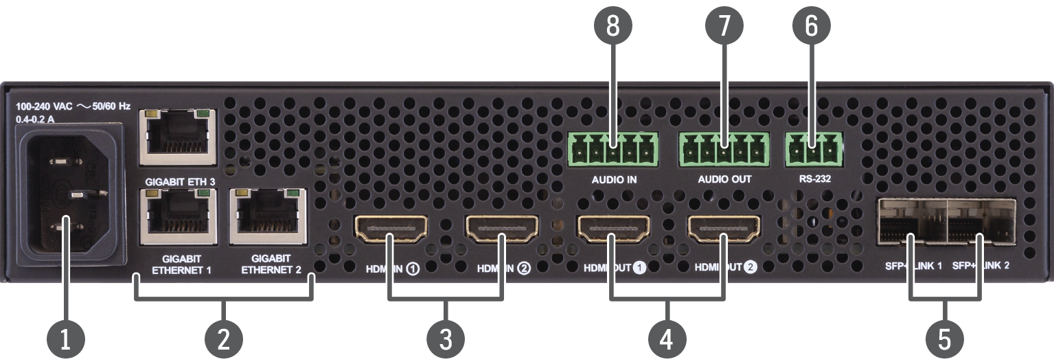
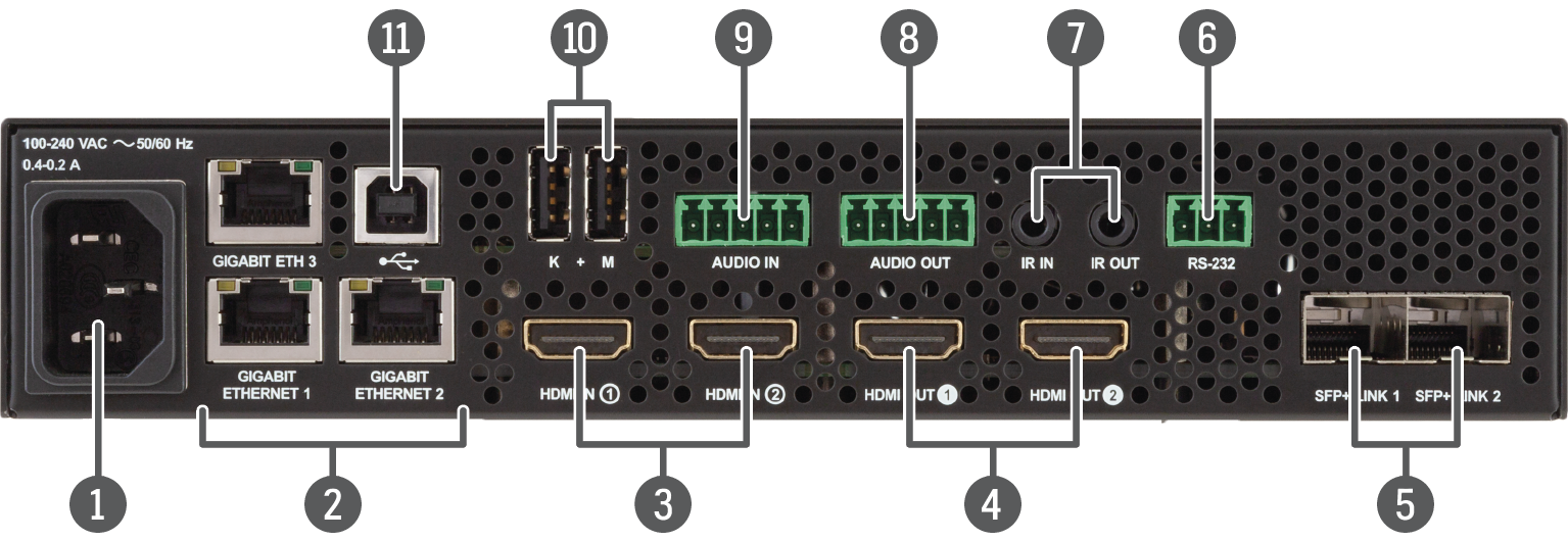
2.1.4. Rear View - F110 / F120 Models
UBEX-PRO20-HDMI-F110
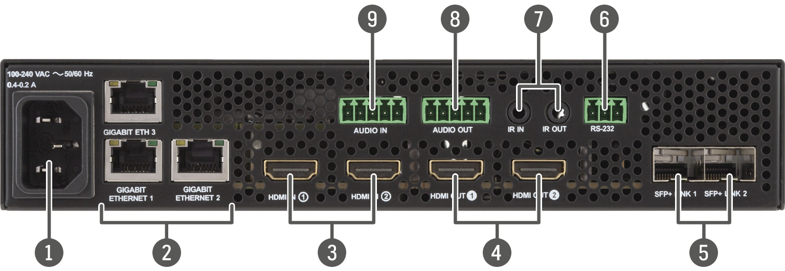
UBEX-PRO20-HDMI-F120
|
|
AC connector |
Standard IEC connector accepting 100-240 V, 50 or 60 Hz. See more details about it in the AC Power Connection section. |
|
|
Ethernet connectors |
Standard locking RJ45 connectors for 1 Gbps Ethernet connections to control the device, for user Ethernet access, and firmware update purpose. See the details about the cable wiring in the Ethernet Connectors section and the concept of the operation in the Ethernet Interface section. |
|
|
HDMI input ports |
HDMI input ports with HDMI 2.0 support for the source devices. When the device is configured as a receiver, the ports operate as local HDMI inputs. The HDMI in 1 port cannot accept AV signal when the device is configured as transceiver. See more details about the HDMI interface in the Video Interface section. |
|
|
HDMI output ports |
HDMI output ports with HDMI 2.0 support for sink devices. When the device is configured as transmitter, the both ports operate as local HDMI outputs. When the device is configured as transceiver, the HDMI out 2 port operates as a local HDMI output. The HDMI out 2 port is able to copy the signal of the HDMI in 1 port when the device is configured as receiver or transceiver. See more details about the HDMI interface in the Video Interface section. |
|
|
SFP+ port slots |
Optical port slots for 2x 10 GbE SFP+ modules or 2x 10 GbE DAC cables. Ports can be used for either singlemode or multimode fiber optical connections. See more details about the SFP+ interface in the SFP / SFP+ Interfaces section. |
|
|
RS-232 connector |
3-pole Phoenix connector for serial communication. See more details about the pin assignment in the RS-232 Connector section, about the cable wiring in the Serial Ports section, and the concept of the operation in the Serial Interface section. |
|
|
Infrared connectors |
3-pole TRS connector, also known as 3.5 mm (1/8”) jack plug for optional IR detector (IR IN) and emitter (IR OUT) connection. See more details about the pin assignment in the IR Connector section, and about the concept of the operation in the Infrared Interface section. |
|
|
Analog audio output port |
5-pole Phoenix connector for balanced analog audio output. The port is available in all operation modes (TX/RX/TRX). See more details about the pin assignment in the Symmetrical Analog Stereo Audio Connector section, about the cable wiring in the Audio Ports section, and about the analog audio interface in the Audio Interface section. |
|
|
Analog audio input port |
5-pole Phoenix connector for balanced analog audio input. The port is available in all operation modes (TX/RX/TRX). See more details about the pin assignment in the Symmetrical Analog Stereo Audio Connector section, about the cable wiring in the Audio Ports section, and about the analog audio interface in the Audio Interface section. |
|
|
USB-A ports |
Two USB-A ports for connecting HID devices (keyboard, mouse, pointer, etc) for USB K+M extension. The port is available in all operation modes (TX/RX/TRX). See more details about the K+M feature in the USB K+M Interface (F120 / F121 Models) section. |
|
|
USB-B port |
USB-B port for connecting the host device (e.g. computer) for USB K+M extension. The port is available in all operation modes (TX/RX/TRX). See more details about the K+M feature in the USB K+M Interface (F120 / F121 Models) section. |
2.2. Front and Rear View - R-series Endpoint Devices
2.2.1. Front View
All Models
|
|
Mounting ears |
Durable mounting ears on both sides of the device for the easy mounting in the case of rental or staging application. The ears serve more purposes, see the details in the Mounting Options - R-series Endpoint Devices section. |
|
|
Status LEDs |
The LEDs give immediate feedback about the current status of the endpoint device. See the details about the operation of the LEDs in the Status LEDs section (on the right side). |
|
|
LCD screen |
LCD screen showing the most important settings and parameters in the front panel menu. The available settings and information depends on the current application mode. See the details in the Front Panel LCD Menu Operation - Endpoints chapter. |
|
|
Jog dial control knob |
Easy setting and menu navigation by the jog dial control. Keep dialing and clicking while getting feedback on the LCD. The operation of the jog dial control knob can be disabled by the control lock feature. The function can be enabled using the following methods: ▪Lightware Device Controller (LDC) software / Built-in website - see the details in the Health Status Tab section; ▪LW3 protocol command - see the details in the Control Lock section. |
|
|
Reset button |
Reboots the device (the same as disconnecting from the power source and reconnecting again). |

|
LIVE |
Transmitter / Receiver / Transceiver |
||
|
|
blinking |
The device is powered and ready to use. |
|
|
|
off |
The device is not powered or out of operation. |
|
|
STATUS |
Transmitter / Receiver / Transceiver |
||
|
|
on |
All measured temperature and voltage values are within the limits. |
|
|
|
blinking |
Measured temperature or voltage value is out of the limits. |
|
|
|
off |
The device is not powered or out of operation. |
|
|
LINK OK |
Transmitter / Receiver / Transceiver |
||
|
|
on |
The connection is established on the fiber optical links and the Link Aggregation is working. |
|
|
|
blinking |
The connection is established on the fiber optical links and LACP detection period is active. |
|
|
|
off |
No connection is established on one of the fiber optical links. |
|
|
MMU AVAILABLE |
Transmitter / Receiver / Transceiver |
||
|
|
on |
Matrix mode is active; the communication is live between the endpoint and the Matrix Management Unit (MMU). |
|
|
|
blinking |
Matrix mode is active; no communication between the endpoint and the MMU. |
|
|
|
off |
Extender mode is active; no communication between the endpoint and the MMU. |
|
Dark Mode
Rental application requires this function, which keeps the LCD screen and the LEDs unlit to hide the device during the event. The function can be enabled via the following methods:
▪Front panel LCD menu - see the details in the Front Panel section;
▪Lightware Device Controller (LDC) software / Built-in website - see the details in the Health Status Tab section;
▪LW3 protocol command - see the details in the Dark Mode Setting section.
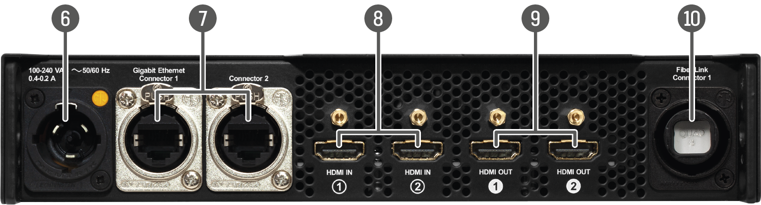
2.2.2. Rear View
UBEX-PRO20-HDMI-R100 2xMM-QUAD and 2xSM-QUAD
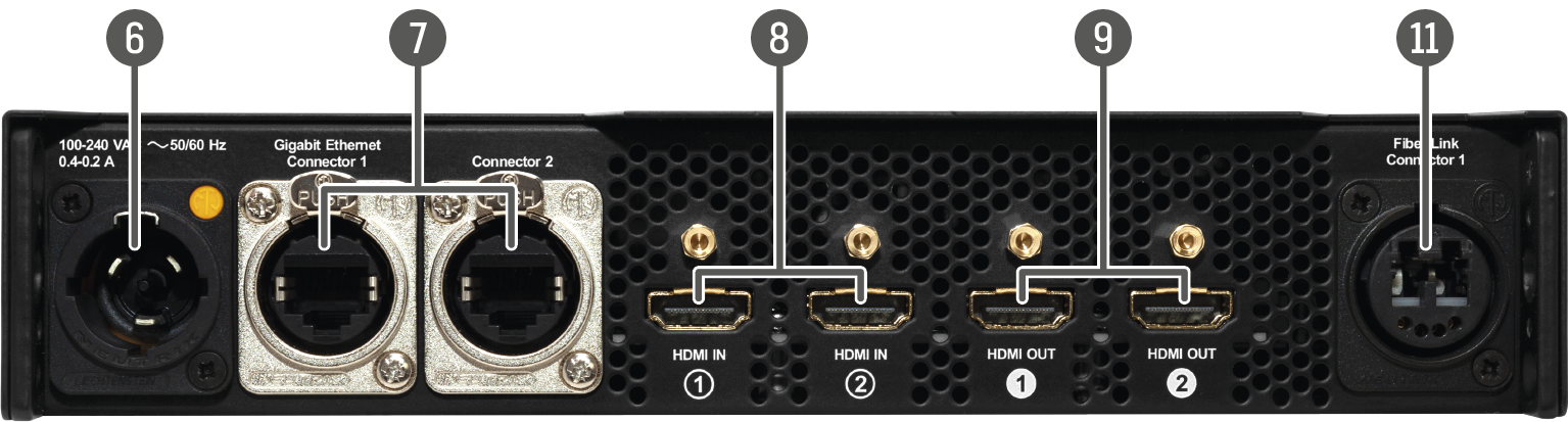
UBEX-PRO20-HDMI-R100 2xSM-BiDi-DUO
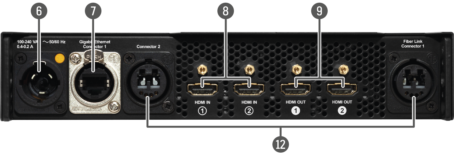
UBEX-PRO20-HDMI-R100 2xMM-2xDUO and 2xSM-2xDUO
|
|
Neutrik powerCON AC connector |
Neutrik powerCON TRUE1 NAC3MPX-WOT connector accepting 100-240 V, 50 or 60 Hz. See more details about it in the AC Power Connection section. |
|
|
Neutrik etherCON Ethernet connectors |
Neutrik etherCON NE8FDV-YK locking RJ45 connectors for 1 Gbps Ethernet connections to control the device, for user Ethernet access, and firmware update purpose. See the details about the cable wiring in the Ethernet Connectors section and the concept of the operation in the Ethernet Interface section. |
|
|
HDMI input ports with flange |
HDMI input ports with HDMI 2.0 support for the source devices. When the device is configured as a receiver, the ports operate as local HDMI inputs. The HDMI in 1 port cannot accept AV signal when the device is configured as transceiver. See more details about the HDMI interface in the Video Interface section. |
|
|
HDMI output ports with flange |
HDMI output ports with HDMI 2.0 support for sink devices. When the device is configured as transmitter, the both ports operate as local HDMI outputs. When the device is configured as transceiver, the HDMI out 2 port operates as a local HDMI output. The HDMI out 2 port is able to copy the signal of the HDMI in 1 port when the device is configured as receiver or transceiver. See more details about the HDMI interface in the Video Interface section. |
|
|
Neutrik opticalCON QUAD optical connector |
Neutrik opticalCON QUAD NO4FDW-A singlemode or multimode fiber optical connector for AV signal transmission. ▪2xMM-QUAD: supports multimode cable connection. ▪2xSM-QUAD: supports singlemode cable connection. See more details about it in the Neutrik opticalCON Connectors section. |
|
|
Neutrik opticalCON DUO BiDi optical connector |
Neutrik opticalCON DUO NO2-4FDW-A singlemode fiber optical connector with BiDi support for AV signal transmission. See more details about it in the Neutrik opticalCON Connectors section. The connector does not support the Neutrik opticalCON crossed fiber wiring (A-A; B-B) cable. Please use standard (A-B) cable only. |
|
|
Neutrik opticalCON DUO optical connector |
2x Neutrik opticalCON DUO NO2-4FDW-A singlemode or multimode fiber optical connectors for AV signal transmission. ▪2xMM-2xDUO: supports multimode cable connection. ▪2xSM-2xDUO: supports singlemode cable connection. See more details about it in the Neutrik opticalCON Connectors section. |


See more details about the fiber optical connectors in the Neutrik opticalCON Connectors section and about the connection possibilities / connector pin layouts in the Connection between the Switch and R-series Endpoints section.
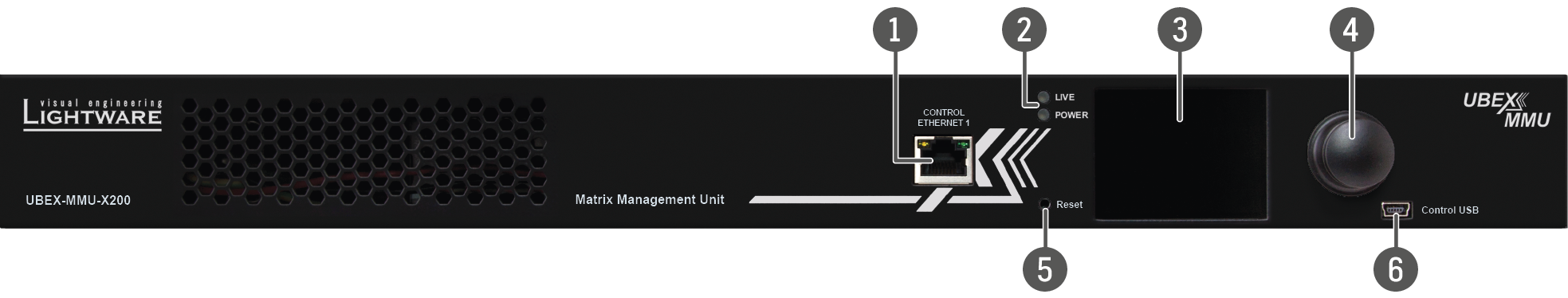
2.3. Front and Rear View - UBEX-MMU-X200
2.3.1. Front View
|
|
Control Ethernet port 1 |
Front panel RJ45 connector for control and firmware update purpose. The port supports 100 Mbps Ethernet connection, auto-negotiation, and auto-MDI/MDIX. See the details about the cable wiring in the Ethernet Connectors section and the concept of the operation in the Ethernet Interface section. |
|
|
Status LEDs |
The LEDs give immediate feedback about the recent status of the device. See the details about the operation of the LEDs in the Status LEDs section below. |
|
|
LCD screen |
LCD screen showing the most important settings and parameters in the front panel menu. See the details the LCD menu operation in the Front Panel LCD Menu Operation - MMU chapter. |
|
|
Jog dial control knob |
Easy setting and menu navigation by the jog dial control. Keep dial and click while getting feedback on the LCD. See the details the LCD menu operation in the Front Panel LCD Menu Operation - MMU chapter. |
|
|
Reset button |
Reboots the device (the same as disconnecting from the power source and reconnecting again). |
|
|
USB connector |
Function will be added by future firmware update. |
|
LIVE |
||
|
|
blinking |
The device operates normally, the core software is running. |

|
on |
Device initialization is in progress. |
|
|
off |
The device is not powered or out of operation. |
|
POWER |
||
|
|
on |
The device is powered and ready to use. |
|
|
off |
The device is not powered or out of operation. |
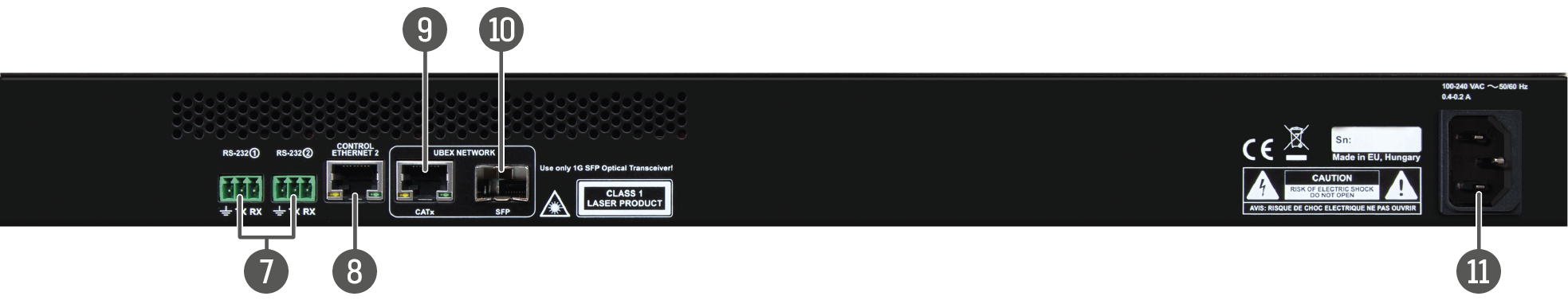
2.3.2. Rear View
|
|
RS-232 connectors |
2 pcs 3-pole Phoenix connectors for serial communication. The connectors are for controlling the device and connection with third-party system controllers. See more details about the pin assignment in the RS-232 Connector section, about the cable wiring in the Serial Ports section, and the concept of the operation in the Serial Interface section. |
|
|
Control Ethernet port 2 |
Rear panel RJ45 connector for control and firmware update purpose. The port supports 1 Gbps Ethernet connection, auto-negotiation, and auto-MDI/MDIX. See the details about the cable wiring in the Ethernet Connectors section and the concept of the operation in the Ethernet Interface section. |
|
|
Ethernet port for UBEX network |
RJ45 connector with 1 GbE support for connection to the UBEX network. Connect the MMU and the L3 network switch by a CATx cable via the connector. See the details about the cable wiring in the Ethernet Connectors section. Use one of the UBEX network connectors (RJ45 or SFP) only in the same time to avoid the network loop. |
|
|
SFP slot for 1 GbE SFP module for UBEX network |
Optical port slots for an 1 GbE SFP module for connection to the UBEX network. Connect the MMU and the L3 network switch by LC fiber optical cable or DAC cable. Ports can be used for either singlemode or multimode fiber optical connections. See more details about the SFP interface in the SFP / SFP+ Interfaces section. Use one of the UBEX network connectors (RJ45 or SFP) only in the same time to avoid the network loop. |
|
|
AC connector |
Standard IEC connector accepting 100-240 V, 50 or 60 Hz. See more details about it in the AC Power Connection section. |
3. Front Panel LCD Menu Operation - MMU
This chapter is about the operating of the Matrix Management Unit, describing the functions that are available by the front panel controls:
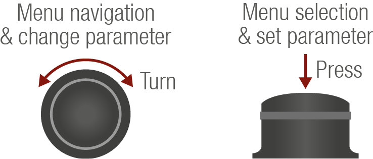
3.1.1. Menu Navigation

The front panel has a color LCD that shows the most important settings and parameters structured in a menu. The jog dial control knob can be used to navigate between the menu items or change the value of a parameter. The knob can be turned and clicked to enter a menu or edit/set a parameter.
3.1.2. Parameter Selection
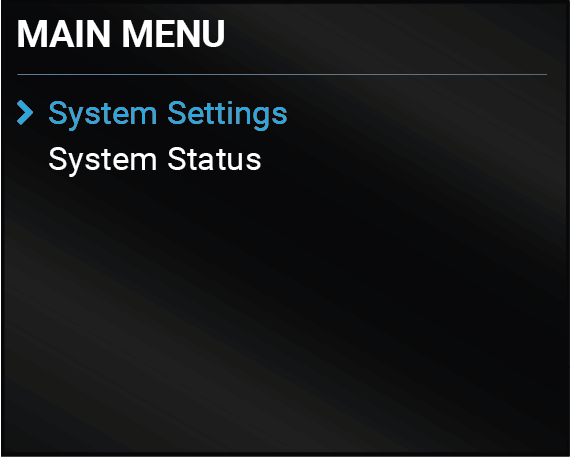
The blue colored line means the selected menu/parameter, the green one means the current setting.
TIPS AND TRICKS:The faster you rotate the jog dial, the faster the parameter list is scrolled.
3.2. System Settings Menu
System related settings are available in the menu - network and time/date settings.
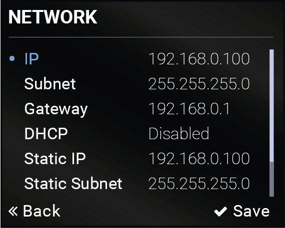
The parameters of the network connection can be set in this submenu. The first three lines (IP, Subnet, and Gateway parameters) show the current settings. If the DHCP option is disabled, three more parameters are listed which can be set for a static IP address:
▪Static IP,
▪Static Subnet,
▪Static Gateway.
ATTENTION!If you change the network settings, always press the Save option under Network menu (not only in the submenu of the parameter) to apply the new settings. #network #dhcp #ipaddress
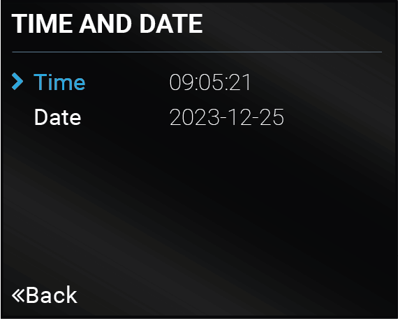
The internal clock and date that is used for logging events can be set in this submenu. #time #date
Time format: HH:MM:SS
Date format: YYYY-MM-DD
TIPS AND TRICKS:The time and date can be set easily in the built-in web or in the Lightware Device Controller software manually or by synchronizing with the local computer. See the details in the System Tab section.

The brightness of the LCD can be set from 1 to 10 on a scale. Use the jog dial control knob to set the brightness lower or higher.
3.2.4. Restart MMU Hardware
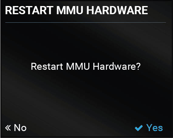
Selecting this submenu makes the MMU reboot. Until the device bootsup, the matrix cannot be managed or controlled, but the AV transmission still operates on its last settings. #restart #reboot
3.2.5. Restore Factory Defaults
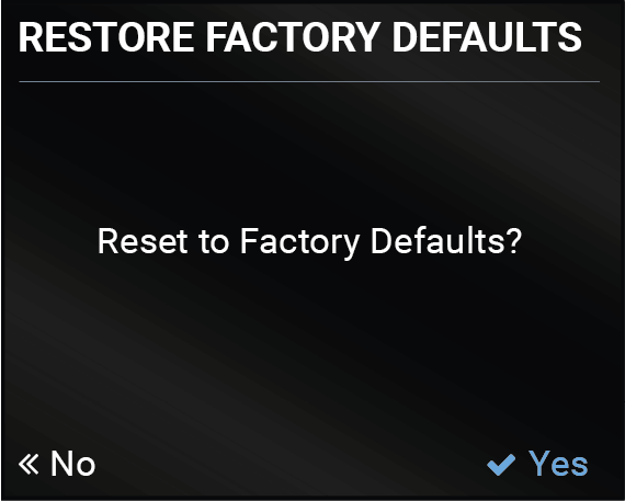
Selecting this submenu results the factory default settings being reloaded after a reboot. See the entire list of restored settings for the Matrix Management Unit in the UBEX-MMU-X200 section. #factory
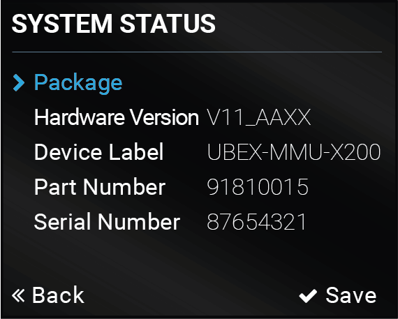
The most important status information about the MMU is displayed in this menu. #status #firmwareversion
Package
Selecting the submenu, detailed information about the installed firmware package of the MMU can be accessed including the pre-installed endpoint firmware package version for the Centralized Firmware Update.
System Information
The hardware version, device label, part number and the serial number of the device is available in the list.
4. Front Panel LCD Menu Operation - Endpoints
This chapter is about the operating of the endpoint device, describing the functions that are available by the front panel controls:
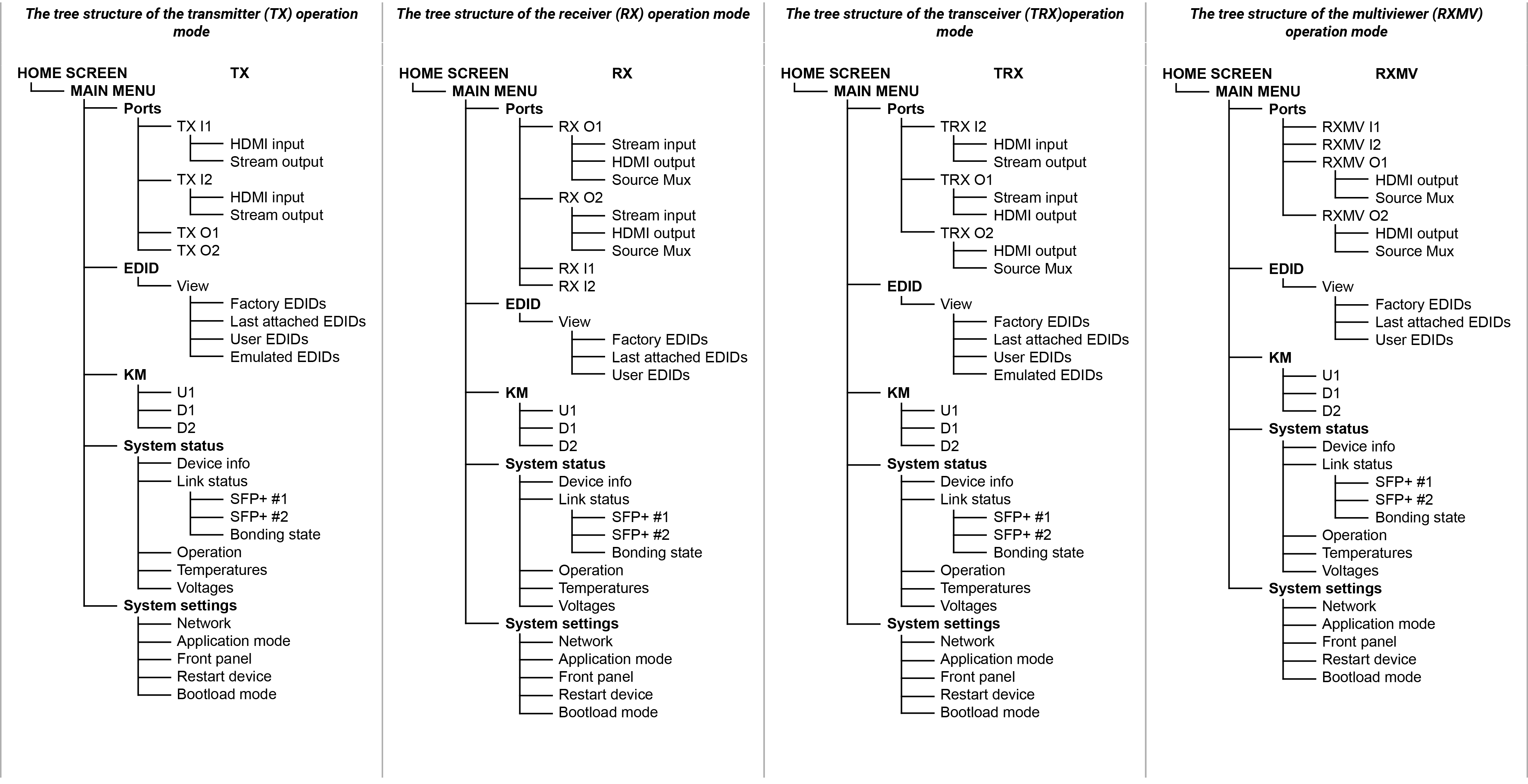
4.1. The Tree Structure of the LCD Menu
4.2.1. Menu Navigation
The front panel has a color LCD that shows the most important settings and parameters structured in a menu. The jog dial control knob can be used to navigate between the menu items or change the value of a parameter. The knob can be turned and clicked to enter a menu or edit/set a parameter.
TIPS AND TRICKS:The faster you rotate the jog dial, the faster the parameter list is scrolled.
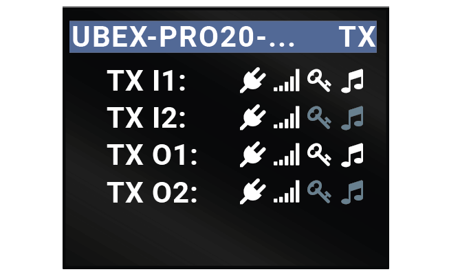
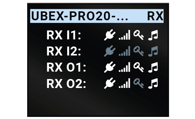
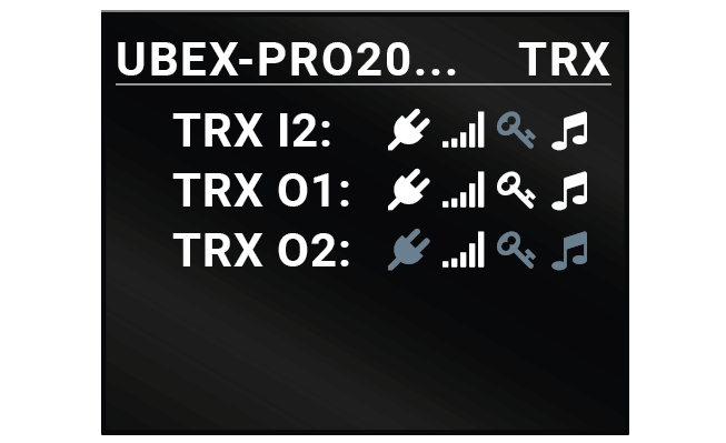
4.2.2. Operation Mode Visualization
The current operation mode of the UBEX endpoint is displayed with two methods on the LCD screen for the easier recognition:
▪The color of the header is blue for the transmitter, white for the receiver and the multiviewer, and black with a white stripe for the transceiver;
▪There is a TX, RX, or TRX label in the main menu of the menu structure.
|
|
|
|
Home screen of the transmitter |
Home screen of the receiver |
Home screen of the transceiver |
4.2.3. Parameter Selection
The blue colored line means the selected menu/parameter, the green one means the current setting.
The current status of the input and output ports of the device is summarized on the Home screen. The device label (which can be modified by the user) and the operation mode is displayed in the top row.
|
|
|
|
|
Home screen of the transmitter |
Home screen of the receiver |
Home screen of the transceiver |
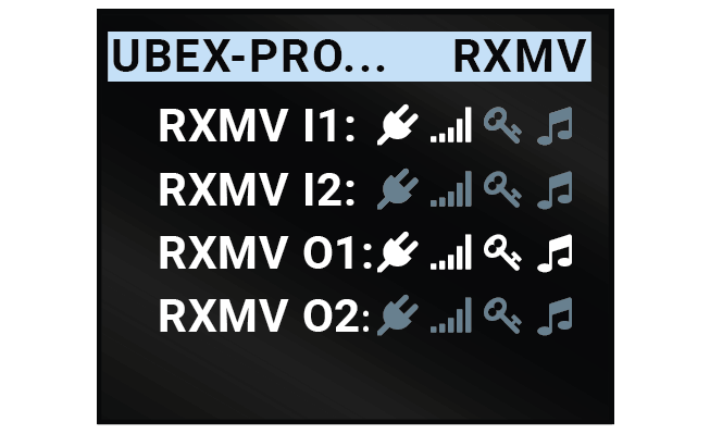
|
||
|
Home screen of the multiviewer |
The device label can be modified via the following methods:
▪Using the Lightware Device Controller (LDC) software - see the details in the Device Information (for TX and TRX operation modes) and in the Device Information (RX, TRX and RXMV operation modes) sections.
▪Using LW3 protocol command - see the details in the Set the Device Label section.
The icons display information about the port and the incoming/transmitted signals.
|
Icon |
Icon is blue (inactive) |
Icon is white (active) |
|
|
Sink is not connected |
Sink is connected |
|
|
Signal is not present |
Signal is present |
|
|
Signal is not encrypted with HDCP |
Signal is encrypted with HDCP |
|
|
No audio signal in the video stream |
Audio is embedded in the video stream |


Take any action (turning or pressing) with the jog dial control knob to enter the Main menu.
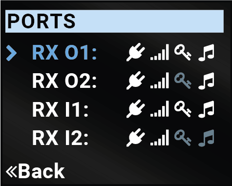
4.4. Ports Menu - Transmitter Operation Mode
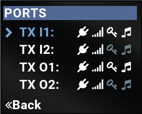
The most important status information of the HDMI input and local output ports are available in the Ports menu.
Select the desired input or output port and enter to see the submenus.
HDMI Input
Information about the HDMI inputs are displayed:
▪+5V present
▪Signal present
▪Active resolution
▪Total resolution
▪Color space
Stream Output
Information about the streams coming from the HDMI inputs are displayed:
▪Signal present
▪Active resolution
▪Total resolution
▪Color space
4.4.2. TX O1 and TX O2 Ports
The following information is displayed for both local output ports:
▪Hotplug detect
▪Signal present
▪Active resolution
▪Total resolution
▪Color space
4.5. Ports Menu - Receiver Operation Mode
The most important status information of the HDMI output ports are available in the Ports menu.
Select the desired output port and enter to see the submenus.
4.5.1. RX HDMI Output 1 and 2 Ports
Stream Input
The following information is related to the video stream coming from the TX input ports:
▪Signal present
▪Active resolution
▪Total resolution
▪Color space
HDMI Output
The following information is displayed in the case of both output ports of the receiver:
▪Hotplug detect
▪Signal present
▪Active resolution
▪Total resolution
▪Color space
Source Mux
The source multiplexer (Source MUX) makes routing several different source signals to the HDMI output ports available. See more details about this function in the Receiver Mode section. #mux #sourcemux
▪Stream (D1) / Stream (D2) - The signal source of the output port is the stream coming from the remote device.
▪Loopback (I1) / Loopback (I2)- The signal source of the output port is the stream of the local input port of the receiver.
▪Copy (O1) - The device is able to copy the signal of the HDMI out 1 port. This is the COPY function.
INFO:The Copy function is available only on the HDMI out 2 (TX O2) port.
The following information is displayed for both local input ports:
The HDCP setting and information about the HDMI inputs are displayed:
▪+5V present
▪Signal present
▪Active resolution
▪Total resolution
▪Color space
4.6. Ports Menu - Transceiver Operation Mode
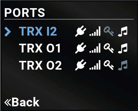
The most important settings and status information of the HDMI input 1 and the HDMI output ports are available in the Ports menu.
Select the desired output port and enter to see the submenus.
HDMI Input
Information about the HDMI input 2 port are displayed:
▪+5V present
▪Signal present
▪Active resolution
▪Total resolution
▪Color space
Stream Output
The following information is related to the video stream that is sent toward the remote TRX endpoint:
▪Signal present
▪Active resolution
▪Total resolution
▪Color space
Stream Input
The following information is related to the video stream coming from the input port of the remote TRX endpoint:
▪Signal present
▪Active resolution
▪Total resolution
▪Color space
HDMI Output
The following information are displayed for the HDMI output 2 port of the transceiver:
▪Hotplug detect
▪Signal present
▪Active resolution
▪Total resolution
▪Color space
4.6.3. TRX O2 Port
The following information is displayed for the local output port:
▪Hotplug detect
▪Signal present
▪Active resolution
▪Total resolution
▪Color space
Source Mux
The source multiplexer (Source MUX) makes routing several different source signals to the HDMI out 2 port available. See more details about this function in the Transceiver Mode section. #mux #sourcemux
▪Loopback (I2)- The signal source of the output port is the stream of the HDMI in 2 port of the transceiver.
▪Copy (O1) - The device is able to copy the signal of the HDMI out 1 port. This is the COPY function.
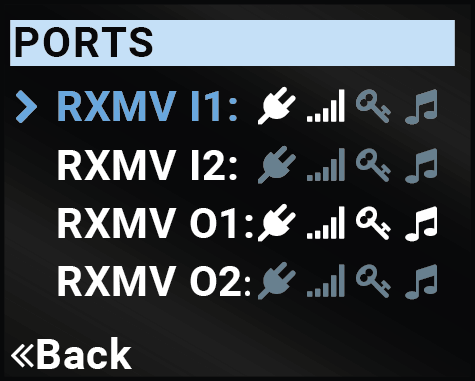
4.7. Ports Menu - Multiviewer Operation Mode
DIFFERENCE:The multiviewer operation mode for the endpoint devices is available only from endpoint firmware package v3.2.0 without MMU support. The MMU support is available from MMU firmware package v2.2.0 which includes the endpoint firmware package v3.3.1 for the centralized firmware update.
The most important status information of the local HDMI input ports and the HDMI output ports are available in the Ports menu. #multiviewer
Select the desired output port and enter to see the submenus.
4.7.1. RXMV I1 and I2 Input Ports
Information about the HDMI inputs are displayed:
▪+5V present
▪Signal present
▪Active resolution
▪Total resolution
▪Color space
4.7.2. RXMV O1 Output Port
HDMI Output
The following information is displayed in case of both output ports of the multiviewer:
▪Hotplug detect
▪Signal present
▪Active resolution
▪Total resolution
▪Color space
Source Mux
The source multiplexer (Source MUX) makes routing several different source signals to the HDMI output ports available. See more details about this function in the Multiviewer Mode section. #mux #sourcemux
▪MV1 - The signal source of the output port is the multiview stream (canvas & tiles).
▪Loopback (I1) - The signal source of the output port is the stream of the local input port of the multiviewer.
4.7.3. RXMV O2 Output Port
HDMI Output
The following information is displayed in case of both output ports of the multiviewer:
▪Hotplug detect
▪Signal present
▪Active resolution
▪Total resolution
▪Color space
Source Mux
The source multiplexer (Source MUX) makes routing several different source signals to the HDMI output ports available. See more details about this function in the Multiviewer Mode section. #mux #sourcemux
▪Stream (D5) - The signal source of the output port is the stream coming from the remote device.
▪Loopback (I2)- The signal source of the output port is the stream of the local input port of the multiviewer.
▪Copy (O1) - The device is able to copy the signal of the HDMI out 1 port. This is the COPY function.
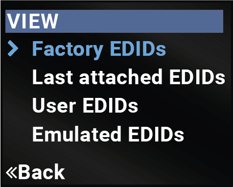
Reduced Advanced EDID Management is available in the front panel LCD menu, which allows for an EDID to be viewed. See more information about EDID technology in the EDID Management section. The EDID memory structure of the device can be found in the Advanced EDID Management section.
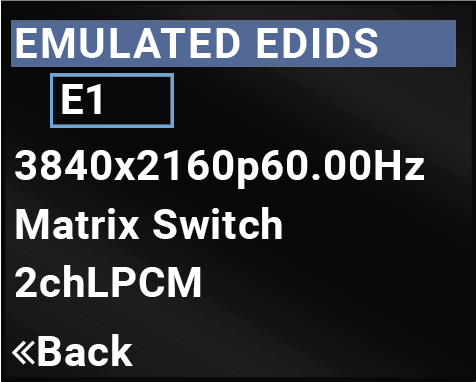
Select the desired EDID memory block: Factory EDIDs, Last Attached EDIDs, User EDIDs, or Emulated EDIDs (only in case of the transmitter). Select the Name item and press the knob. Use the jog dial to step between the EDIDs. The following information can be checked:
▪Preferred Resolution
▪Monitor Name
▪Audio Info
4.9. KM Menu
DIFFERENCE:This menu is available in the UBEX-PRO20-HDMI-F120, UBEX-PRO20-HDMI-F121 and UBEX-PRO20-HDMI-F130 models only. #km #usbkm #kvm #usbkvm
The most important settings and status information of the USB K+M function are displayed in the menu. Three submenus are under the KM menu: U1, D1 and D2. The following table describes the meaning of these ports:
|
USB Port |
Physical port |
Description |
|
U1 |
USB-B |
U as Upstream |
|
D1 |
USB-A (right (M) side) |
D1 as Downstream 1 |
|
D2 |
USB-A (left (K) side) |
D2 as Downstream 2 |
Available Information:
▪Device State
▪VBus Present
Available Information:
▪Device Present
▪Interface Classes
▪Device Class
▪Product Name
▪Manufacturer
▪Enumeration State
▪Composite Capability
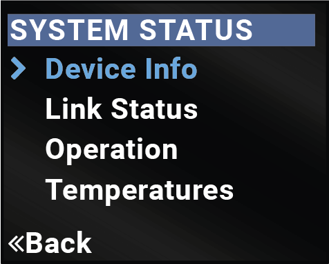
The most important status information is displayed about the endpoint in the menu.
Device Info
Hardware- and software-related information is listed in the submenu, e.g. device label - this is a user defined unique name, which can be set in the LDC software (see the details in the Status Tab section) or with LW3 protocol command (see the details in the Set the Device Label section), and serial number, firmware version, etc.
The current status of the optical or DAC connection, advanced information about the installed SFP+ modules, and the bonding state are available under the menu. #uplink #link #sfp
▪SFP+ #1 / SFP+ #2 Link State
=Up - The connection between the SFP+ link of the endpoint and the network switch is up.
=Down - There is no connection between the SFP+ link of the endpoint and the network switch.
=Waiting for Aggregation - The connection is established on the fiber optical links, temporary LACP detection period is active.
▪Bonding State - Aggregated State
=OK - Link aggregation protocol is working correctly.
=LACP Error - Link aggregation protocol error appeared during the active LACP detection period.
▪Bonding State - Total Bandwidth
=0.00 Gbps - No connection one of the SPF+ link.
=10.00 Gbps - Connection is established on one 10G SFP+ link.
=20.00 Gbps - Connection is established on both 10G SFP+ links.
INFO:See more practical troubleshooting use cases in the Network Diagnostics for UBEX Matrix section.
Operation
The uptime and the operation time can be read out from the menu.
Temperatures
The recent temperature of the CPU, the system, and the FPGA are displayed in the menu.
ATTENTION!If the front panel Status LED blinks, check the temperatures under this menu and ensure the correct air flow for the device.
Voltages
The recent voltages of the device are displayed in the menu.
WARNING!If the front panel Status LED blinks, power off the device immediately.
System related settings are available in the menu, e.g. application mode changing (from matrix mode to extender mode), front panel settings, reset the device, etc.
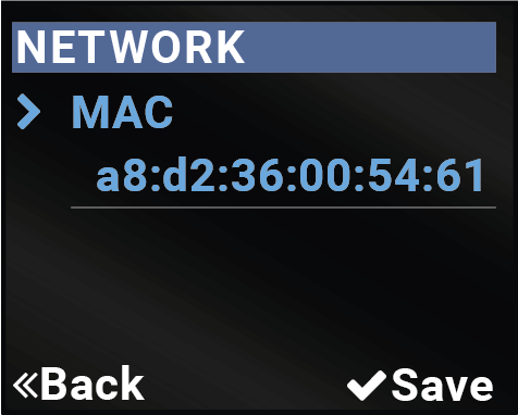
The MAC address of the device can be read out in the menu.
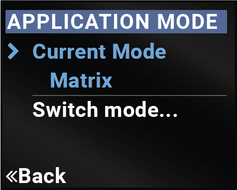
The current application mode (Extender or Matrix) is displayed in this submenu. For more details about the two modes, see the Application Modes section.
ATTENTION!The application change is not allowed when the endpoint device is connected to the MMU.
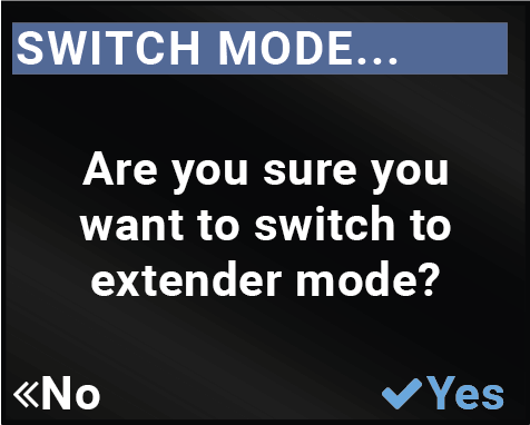
Follow the steps to change the application mode to Extender mode:
Step 1.Navigate to the System Settings / Application Mode submenu.
Step 2.Select the Switch Mode... option.
Step 3.Confirm the selection, press the Yes.
Step 4.The endpoint changes the application mode to Extender immediately.
#applicationmode #extendermode #matrixmode
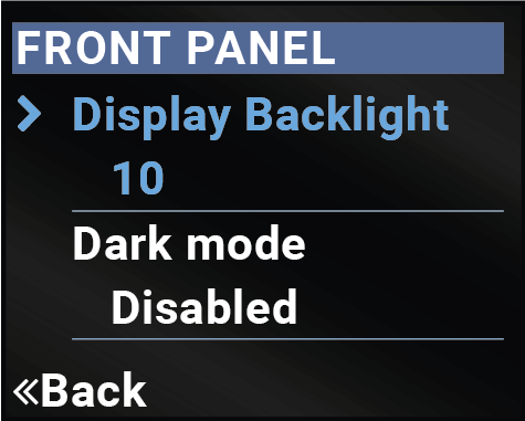
Display Backlight
The brightness of the LCD can be set from 1 to 10 on a scale.
Dark Mode
The dark mode feature can be enabled or disabled. It keeps the LCD screen and the LEDs unlit to hide the device during an event when the mode is enabled. #darkmode
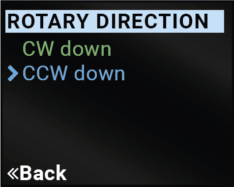
Rotary Direction
The rotary direction of the jog dial control knob can be set in two ways: CW Down (clockwise down) or CCW Down (counter clockwise down). #rotary #jogdial
This setting makes it possible to restart the device. It results in a reboot only and DOES NOT reload the factory default settings. #restart #reboot
Special function for entering the firmware update mode (bootload mode). #bootload
This chapter is about the installation of the device and connecting to other appliances, presenting also the mounting options and further assembly steps:
5.1. Mounting Accessory Compatibility Table
The following table summarizes the compatiblity of the UBEX F-series and R-series devices with the mounting accessories offered by Lightware. The number in the brackets means how many same-size devices can be assembled to the mounting plate. If there is no number, only one device can be mounted. The dimensions are in mm. The following accessories can be ordered separately, please contact sales@lightware.com for the details.

5.2. Mounting Options - F-series Endpoint Devices
Devices can be mounted in several ways, depending on the application. Besides using with rack shelf, a mounting bracket is available, which offers easy mounting on truss systems with standard clamps. The bracket can also be used for building the unit into the furniture:
WARNING!Always use the supplied screws. Using different (e.g. longer) ones may cause damage to the device.
ATTENTION!Pay attention to the ventilation holes when designing the system, especially when the extender is built into/under furniture. Front and rear ventilation holes must not be covered. If a UBEX device is installed in a closed space, the designer shall provide satisfactory ventilation to prevent excessive heat build-up inside.
INFO:The endpoint device is half-rack sized.
To order mounting accessories, please contact .
Mounting bracket V2 gives an opportunity to mount the device to any furniture surface. Fasten the bracket on the side of the unit with the provided screws, and fasten it to a stand / board / truss / furniture.
Fixing the Bracket to the Device
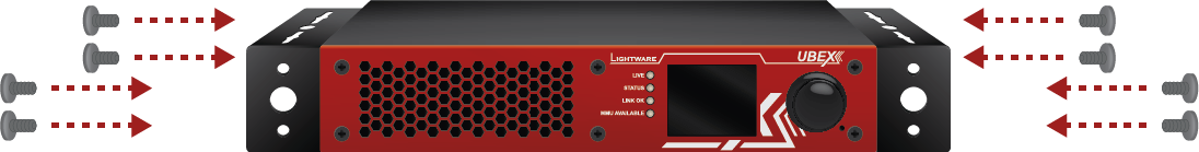
Fasten the mounting bracket on the side of the unit with the provided screws (4 pcs M3 screws per Mounting bracket V2).
WARNING!M3x6 size is the longest allowed screw for fixing the ears to the housing. Using different (e.g. longer) ones may cause damage to the device.
Furniture Mounting
WARNING!Pay attention to the ventilation holes when designing the system. Front and rear ventilation holes must not be covered.
INFO:The chipboard screws are not supplied with the mounting kit.
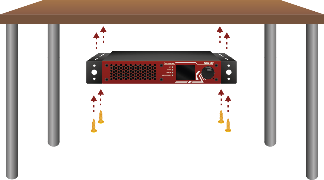
UD mounting plate F120 gives an opportunity to mount the device to any furniture surface. Fasten the plate on the bottom of the unit with the provided screws, and fasten it to a stand / board / furniture.
Fixing the Plate to the Device
Fasten the mounting plate on the bottom of the unit with the provided screws (4 pcs M3 screws).
WARNING!M3x6 size is the longest allowed screw for fixing the ears to the housing. Using different (e.g. longer) ones may cause damage to the device.
Furniture Mounting
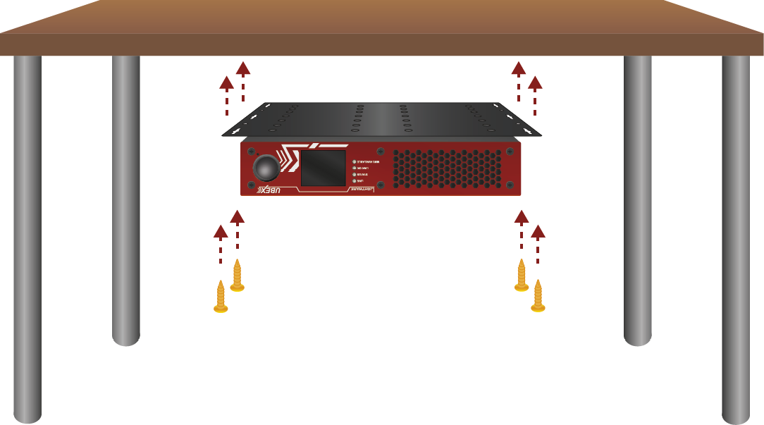
WARNING!Pay attention to the ventilation holes when designing the system. Front and rear ventilation holes must not be covered.
INFO:The chipboard screws are not supplied with the mounting kit.
Allows rack mounting for half-rack, quarter-rack and pocket sized units.
1U high rack shelf provides mounting holes for fastening two half-rack or four quarter-rack sized units. Pocket sized devices can also be fastened on the self.
WARNING!Pay attention to the ventilation holes when designing the system. Front and rear ventilation holes must not be covered.
INFO:The screws for the rack frame are not supplied with the device.
5.3. Mounting Options - R-series Endpoint Devices
UBEX R-series endpoint devices can be mounted in several ways, depending on the application. They can be mounted into the rack in pairs, or can be used standalone. Rack ears also serve easy handling and bump protection, and there are mounting threads on top and one side to conform strict installation safety regulations.
ATTENTION!To ensure the correct ventilation and avoid overheating, leave enough free space in front of and behind of the appliance and keep the ventilation holes free.
5.3.1. Truss Mounting
There are mounting threads on top and on one side for safe and secure installation. Rigging the handles with a safety wire rope is highly recommended for safety reasons.
To order mounting accessories, please contact sales@lightware.com. (Truss clamp and safety wire rope are not available for sales.)
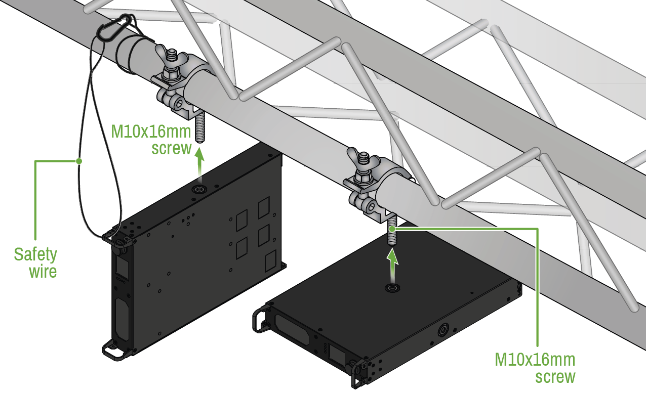
Truss mounting for R-series endpoint devices
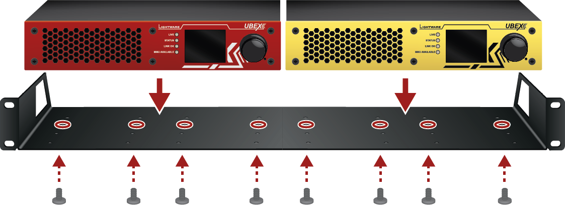
5.3.2. Standard Rack Installation with Two Units
Rack mounting kit includes all necessary accessories for standard rack installation:
▪2 pcs rack ears (PN: 52400959 (2x)),
▪12 pcs. black, M4x8mm hexagon socket countersunk head screws.
Rack mounting kit is not supplied with the product, it can be purchased separately, please contact sales@lightware.com.
Step 1.Take two devices directly next to each other.
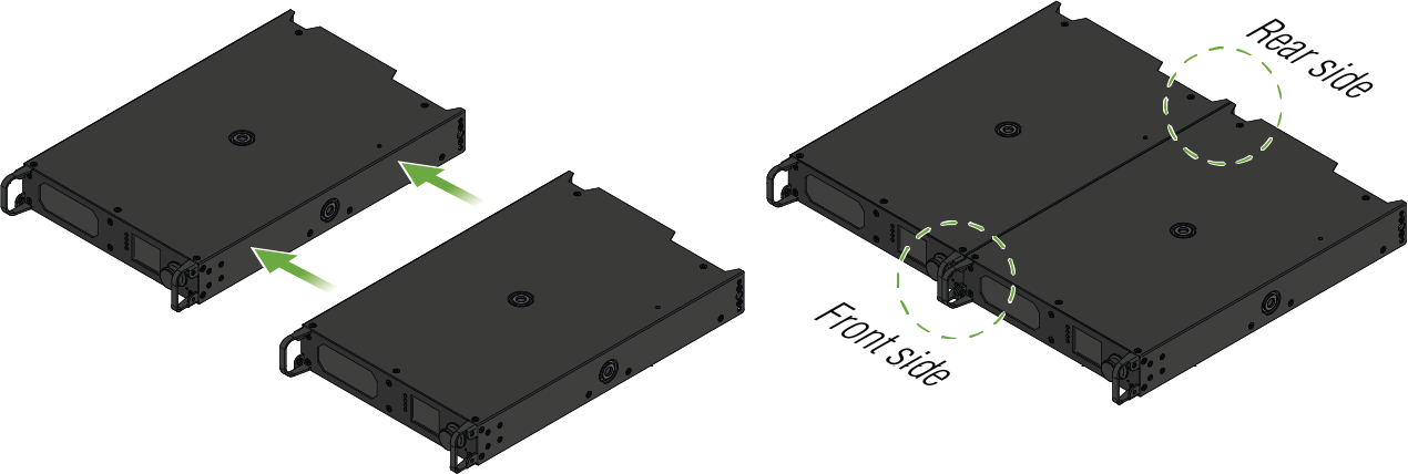
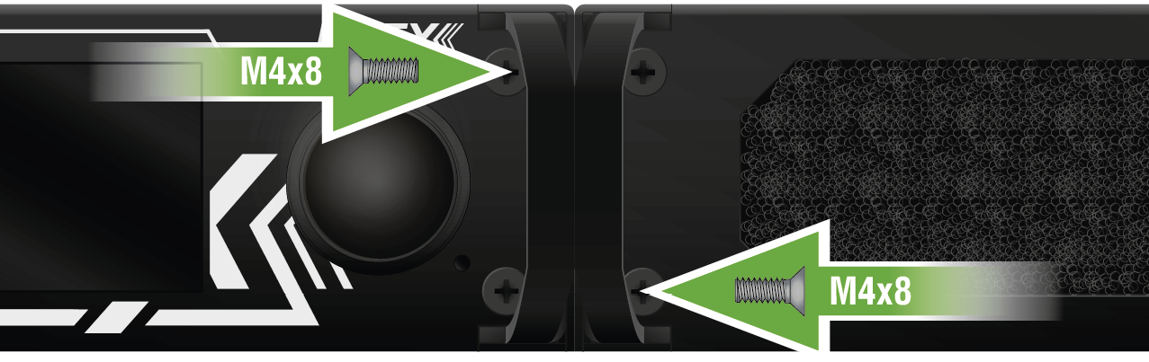
Step 2.Two mounting holes on the front ears and two on the back of the chassis is for fastening the two units to each other with 2x 2 pcs M4x8 mm screws. This way you get a one-rack wide and 1U high device.
Front View
Rear View
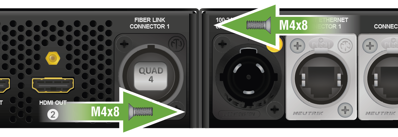
ATTENTION!Take care of the mounting direction of the screws!
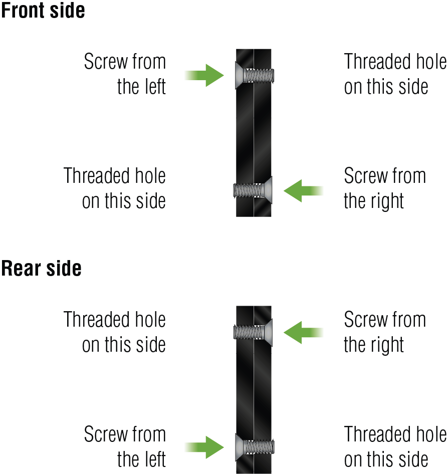
Mounting direction of the screws
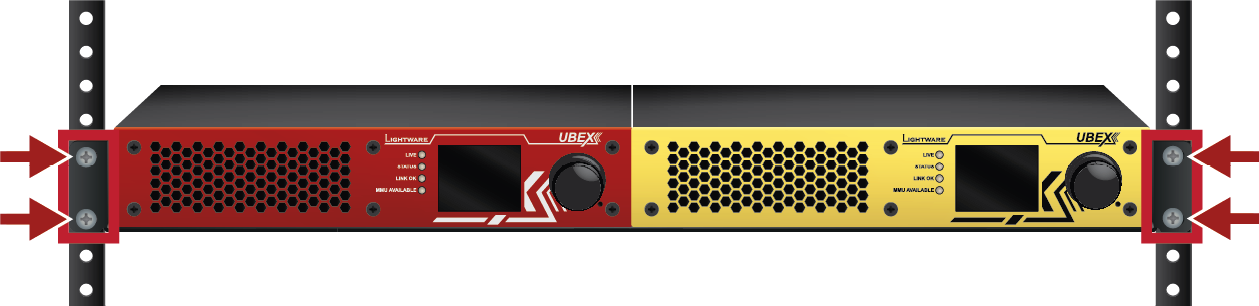
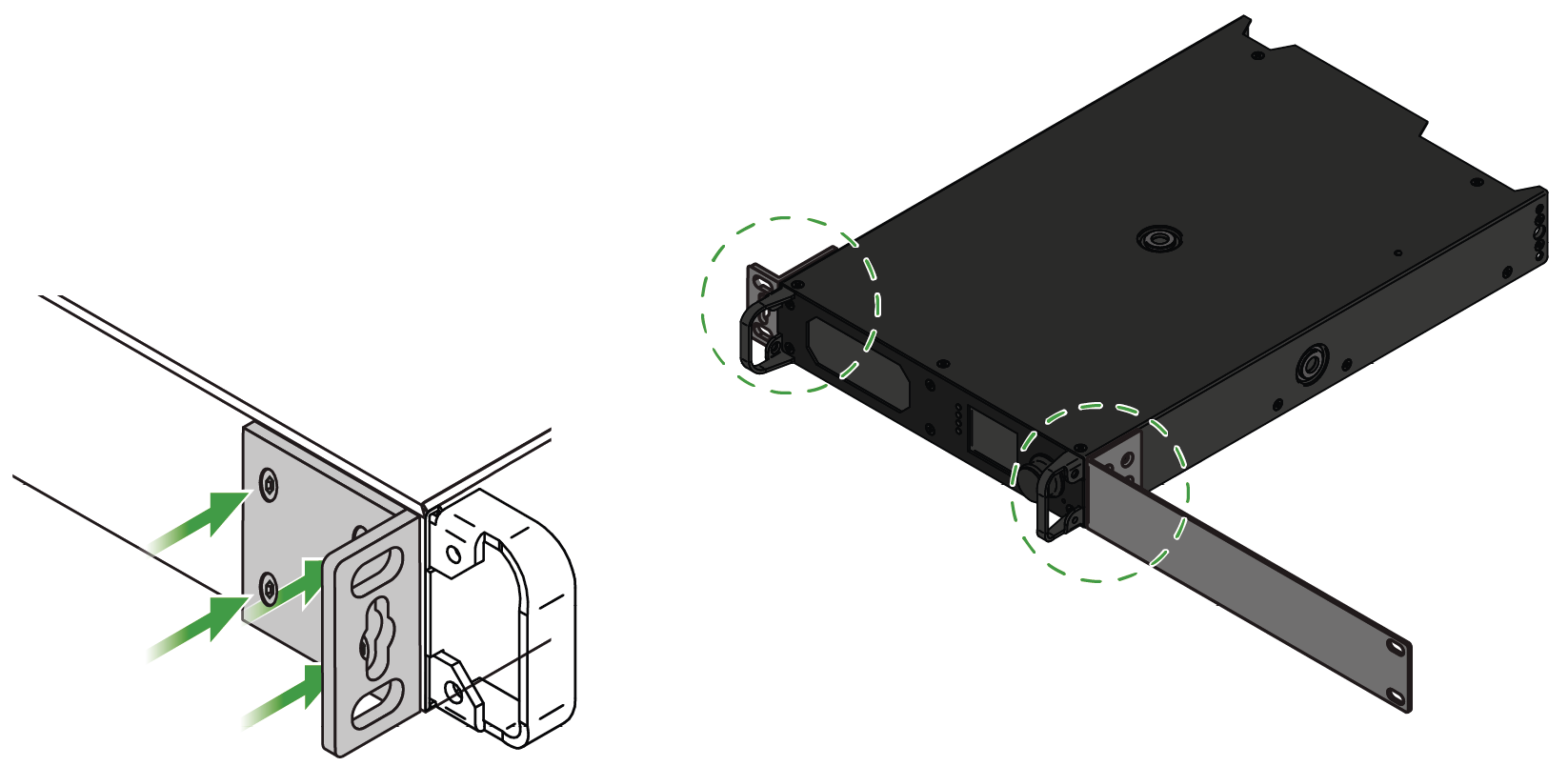
Step 3.Take the rack ears on the left and right side of the extender pair as shown in the picture. Insert the screws into the holes and fix the front ears to the devices.
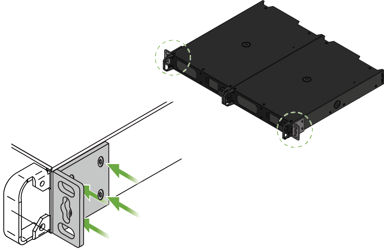
Assembly of the mounting ears
Step 4.As a final step, mount the unit in the rack.
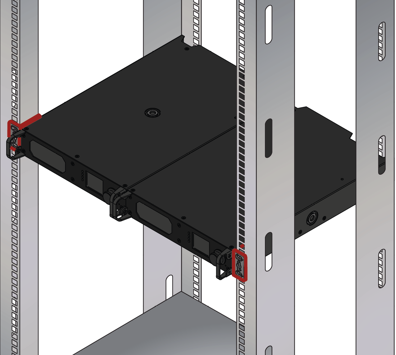
Standard rack installation
ATTENTION!Always use all four screws for fixing the rack ears to the rack rail. Choose properly sized screws for mounting. Keep a minimum of two threads left after the nut screw.
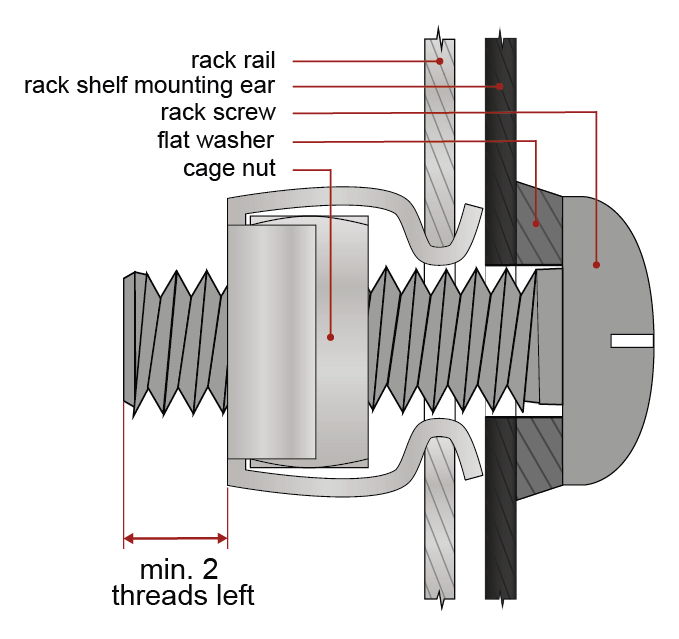
Mounting the rack ears to the rack rail
5.3.3. Standard Rack Installation with One Unit
Lightware provides a rack installation possibility for only one R100 unit with a standard and an extended rack ears. The rack mounting kit includes all necessary accessories for standard rack installation:
▪2 pcs rack ears (PN: 52400959 (1x) and 55450168 (1x)),
▪8 pcs black, M4x8mm hexagon socket countersunk head screws.
Rack mounting kit is not supplied with the product, it can be purchased separately, please contact sales@lightware.com.
Step 1.Take the rack ears on the left and right side of the extender pair as shown in the picture. Insert the screws into the holes and fix the front ears to the devices.
Assembly of the mounting ears
Step 2.As a final step, mount the unit in the rack.
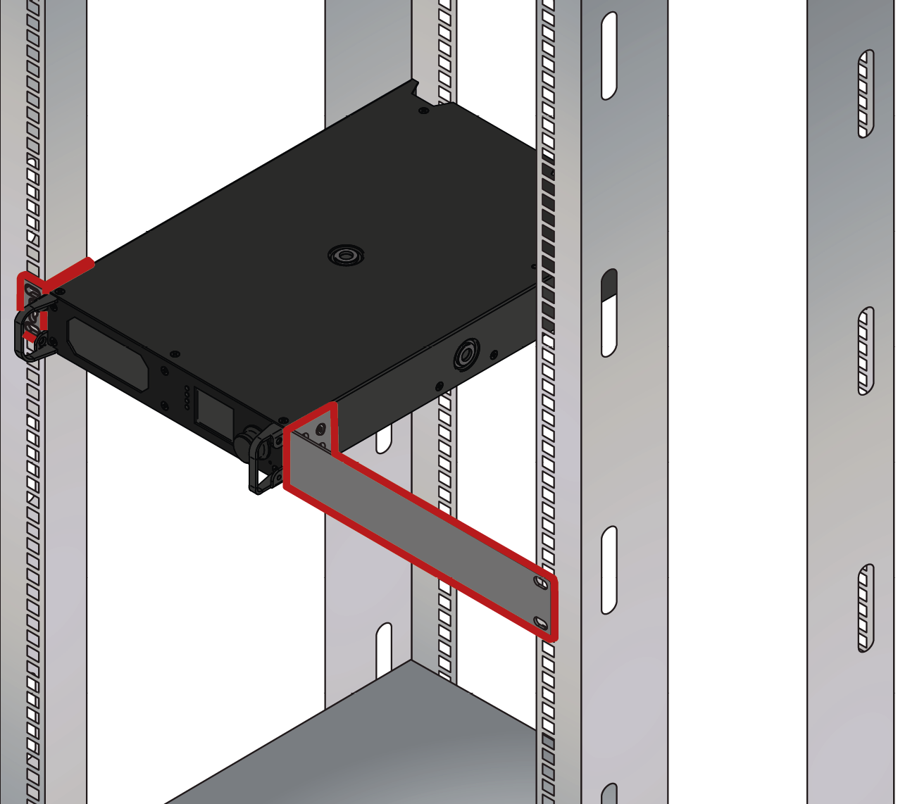
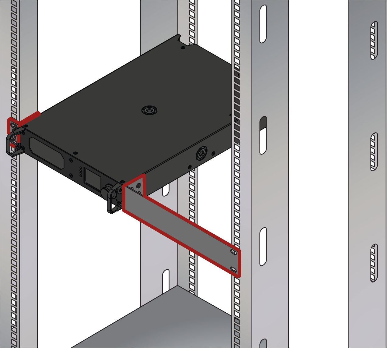
Standard rack installation
ATTENTION!Always use all four screws for fixing the rack ears to the rack rail. Choose properly sized screws for mounting. Keep a minimum of two threads left after the nut screw.
Mounting the rack ears to the rack rail
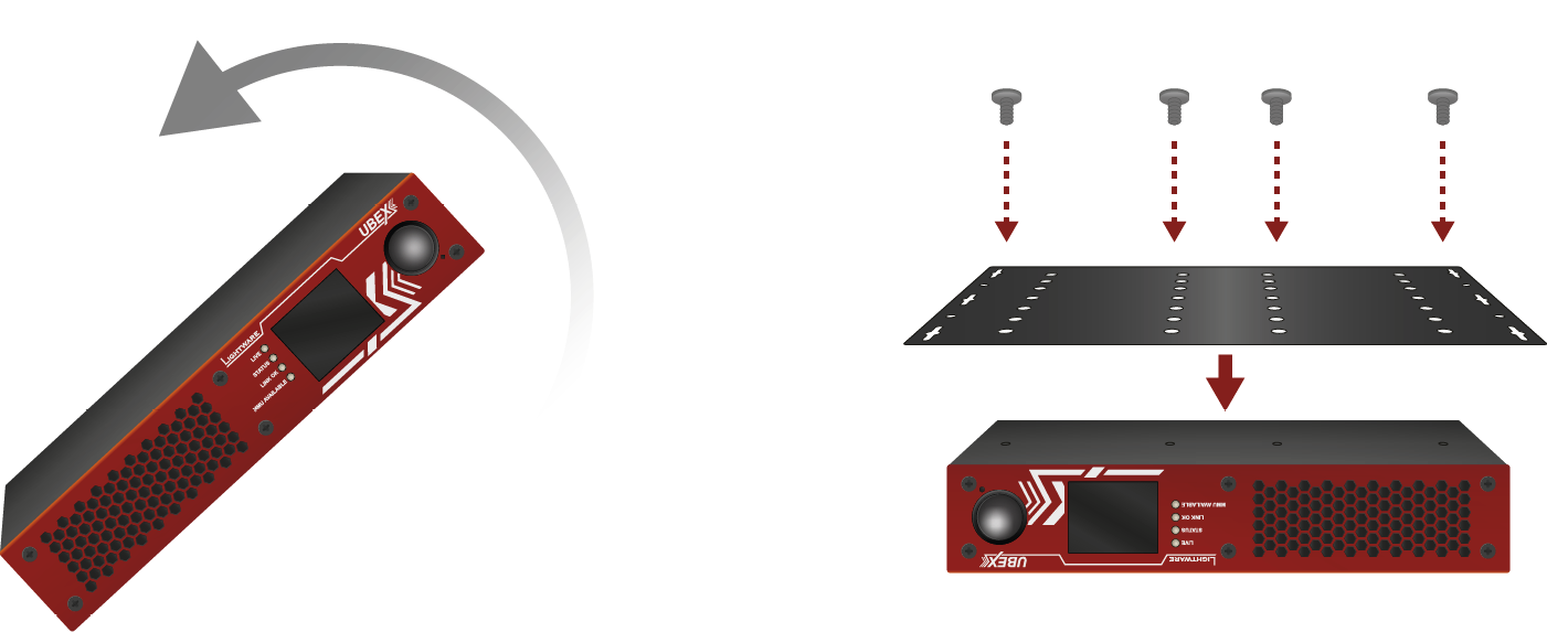
5.4. Rack Shelf Mounting - MMU
Two rack ears are supplied with the product, which are fixed on left and right side with 2x 4 pcs M4 screws. The default position allows mounting the device as a standard rack unit installation.
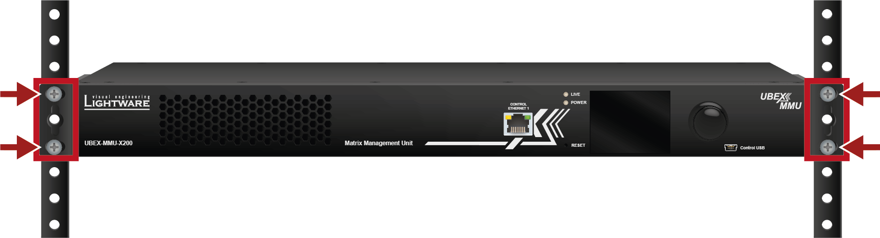
WARNING!M4x8 size is the longest allowed screw for fixing the ears to the housing. Using different (e.g. longer) ones may cause damage to the device.
WARNING!Pay attention to the ventilation holes when designing the system. Front and rear ventilation holes must not be covered.
INFO:The screws for the rack frame are not supplied to the device.
INFO:The device is rack sized and 1U high.
The following sections describe all possible electrical connections of the UBEX endpoint and MMU devices.


The small form-factor pluggable (SFP) is a compact, hot-pluggable optical module transceiver used for both telecommunication and data communication applications. It is a popular industry format jointly developed and supported by many network component vendors. The SFP interface supports data rates up to 1 Gbit/s. *
DEFINITION:The enhanced small form-factor pluggable (SFP+) is an enhanced version of the SFP that supports data rates up to 10 Gbit/s. *
UBEX F-series endpoint devices and the Matrix Management Unit contain standard 1x SFP (in the case of the MMU) and 2x SFP+ (in the case of the endpoint devices) slots for the fiber optical connections via SFP / SFP+ modules or DAC cables. The installed SFP / SFP+ modules can be singlemode or multimode as well.
|
F-series endpoint devices |
MMU |
|
|
Number of slots |
2 |
1 |
|
Type of the slot |
SFP+ |
SFP |
|
Maximum bandwidth per slot |
10 Gbps |
1 Gbps |
|
Transmitted signal |
Audio, video, Ethernet, RS-232, Infrared, USB K+M, USB KVM, USB 2.0 |
Ethernet only |
For the details about the DAC cable / SFP+ module installation, see the SFP / SFP+ Slot Connection section.
Maximum Allowed Cable Length
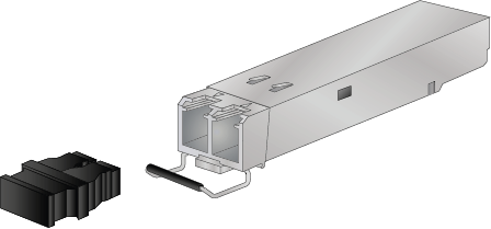
The maximum allowed optical or copper cable length depends of the installed SFP / SFP+ modules. Always check the specification of the optical modules before the fiber optical or copper cabling.
ATTENTION!Always apply equal length copper cables for both SFP+ to RJ45 modules in one endpoint device. Different cable lengths may cause data package lost during the transmission.
* Source: https://en.wikipedia.org/wiki/Small_form-factor_pluggable_transceiver
Standard IEC Connector

UBEX F-series endpoint devices and the Matrix Management Unit contain standard IEC power connector and work with 100 to 240 Volts AC, 50 Hz or 60 Hz power sources.
Connect the power cord to the AC input connector; the extender is immediately powered on.
Neutrik powerCON TRUE1 Connector

UBEX R-series endpoint devices contain Neutrik powerCON TRUE1 NAC3MPX-WOT power connector and work with 100 to 240 Volts AC, 50 Hz or 60 Hz power sources.
Connect the Neutrik powerCON to the AC input connector; the extender is immediately powered on.
See the details about the assembly instructions for the Neutrik powerCON TRUE1 cables on the website of the vendor:
https://www.neutrik.com/en/product/nac3mx-w-top
5.5.3. Symmetrical Analog Stereo Audio Connector
5-pole Phoenix connector is used for balanced analog audio (line in/out). Unbalanced audio signals can be connected as well. For asymmetrical output, connect only + and ground. For asymmetrical input connect + and ground to the source and connect – to the ground.
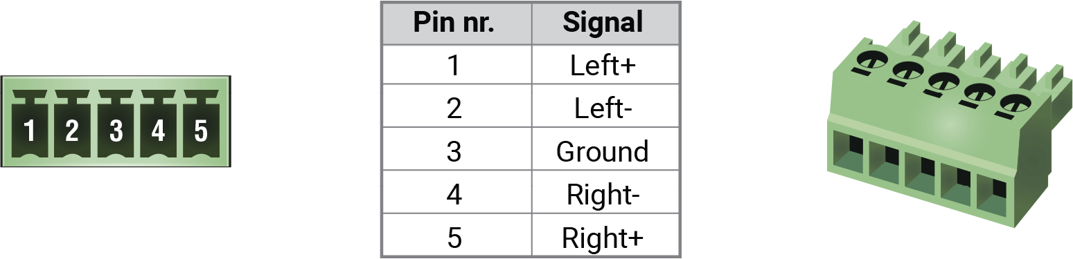
5-pole Phoenix connector pin assignments
Compatible Plug Type
Phoenix® Combicon series (3.5mm pitch), type: MC 1.5/5-ST-3.5.
See more information about the most common audio cable wiring modes in the Audio Ports section.
You can find more information about audio embedding and de-embedding functions in the Audio Interface section.

UBEX-PRO20-HDMI-F120, -F121 and -F130 endpoint models provide USB-A connectors for supporting K+M functionality. The device has 2 pieces of USB 2.0 A-type connectors.
ATTENTION!The USB K+M function supports emulated (composite) mode only. It means in the practice the perfect usage of special keyboard/mouse buttons (e.g. multimedia keyboards and touchpads) are not guaranteed because of the limitation of the emulated mode technology. Lightware recommends usage of ordinary keyboards built up to 104/105 keys and ordinary mice.
5.5.5. USB-B Connector
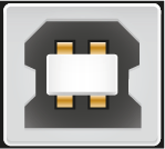
UBEX-PRO20-HDMI-F120 endpoint model provides a USB-B connector for supporting K+M functionality. The device has 1x USB 2.0 B-type connector.
UBEX-PRO20-HDMI-F110 / F120 / F130 endpoint models and the Matrix Management Unit contains a 3-pole Phoenix connector, which is used for RS-232 serial connection.

RS-232 connector pin assignments
Compatible Plug Type
Phoenix® Combicon series (3.5mm pitch, 3-pole), type: MC 1.5/3-ST-3.5.
You can find help for the correct wiring in the Serial Ports section.
You can find more information about serial interface in the Serial Interface section.
5.5.7. USB Mini-B Connector

UBEX series devices provide standard USB 2.0 mini B-type connector for software control and firmware update purpose.
INFO:The USB control function of the MMU will be added by future firmware update.
5.5.8. USB-C Connector

UBEX-PRO20-HDMI-F121 and -F130 endpoint models provide a USB Type-C connector for USB connection between the extender and the host computer.
ATTENTION!The port receives USB data only, no AV signal transmission is accepted. It supports USB 2.0 standard only.

IR detector and IR emitter can be connected to the enpoint device with TRS (Tip, Ring, and Sleeve) connectors. They are also known as (3,5 mm or approx. 1/8”) audio jack, phone jack, phone plug, and mini-jack plug. The pin assignments are the following for the detector and the emitter:

|

|
||
|
Detector – 3-pole TRS |
Emitter – 2-pole TS |
||
|
1 Tip |
Signal (active low) |
1 Tip |
+5V |
|
2 Ring |
GND |
2 Ring |
Signal (active low) |
|
3 Sleeve |
+5V |
3 Sleeve |
|
INFO:Ring pole of the emitter is optional. If your IR emitter has three-pole TRS plug, then the Ring and the Sleeve are the same signal (Output - ).
You can find more information about IR interface in the Infrared Interface section.
5.5.10. HDMI Connector

The endpoint device provides standard 19-pole HDMI connector for inputs and outputs with HDMI 2.0 support. Always use high quality HDMI cable for connecting sources and displays.
See more details about the AV interfaces in the Video Interface and the Audio Interface sections.
Standard RJ45 Connector
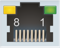
UBEX F-series endpoint devices and the Matrix Management Unit provide standard RJ45 connectors for LAN and user Ethernet access. Always use high quality Ethernet cable.
Neutrik etherCON Connector

UBEX R-series endpoint devices provide Neutrik etherCON NE8FDV-YK connector for LAN and user Ethernet access.
ATTENTION! The connector does not work with CAT6 cable connector (NE8MC6-MO) and NKE6S* cables.
Wiring of LAN Cables
Lightware recommends the termination of LAN cables on the basis of TIA/EIA T 568 A or TIA/EIA T 568 B standards.
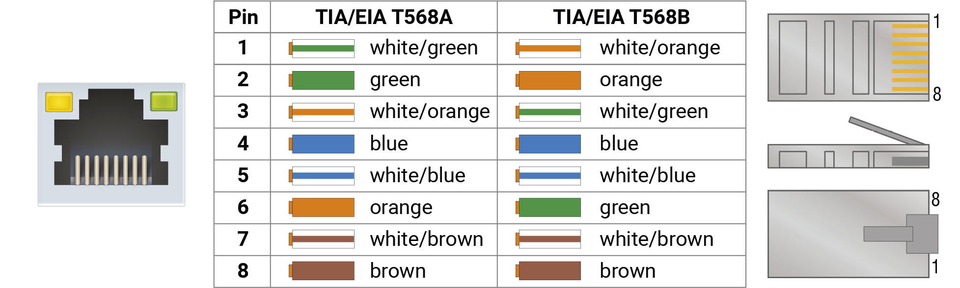
Wiring of LAN cables by types
WARNING!Never connect non-assembled CATx cable to the port while the unit is powered, it may damage the device.
5.5.12. Neutrik opticalCON Connectors
UBEX R-series endpoint devices are built with singlemode or multimode Neutrik opticalCON connectors.
|
UBEX-PRO20-HDMI-R100 models |
|||||
|
2xMM-2xDUO |
2xSM-2xDUO |
2xSM-BiDi-DUO |
2xMM-QUAD |
2xSM-QUAD |
|
|
Number of connectors |
2 |
2 |
1 |
1 |
1 |
|
Connector drawing |

|

|
|||
|
Connector type |
NO2-4FDW-A |
NO4FDW-A |
|||
|
Type of the SFP+ module inside the enclosure |
2x Finisar FTLX8574D3BCL |
2x Finisar FTLX1475D3BCL |
Module A: 1x Finisar FTLX2072D327 |
2x Finisar FTLX8574D3BCL |
2x Finisar FTLX1475D3BCL |
|
Module B: 1x Finisar FTLX2072D333 |
|||||
|
Mode |
Multimode |
Singlemode |
Singlemode |
Multimode |
Singlemode |
|
Supported cable |
LC, Neutrik opticalCON DUO |
LC, Neutrik opticalCON DUO |
LC, Neutrik opticalCON DUO |
Neutrik opticalCON QUAD |
Neutrik opticalCON QUAD |
|
Number of required optical cables for 20GbE |
2x Neutrik opticalCON DUO / 4x LC simplex / 2x LC duplex |
1x Neutrik opticalCON DUO / 2x LC simplex |
1x Neutrik opticalCON QUAD |
||
ATTENTION!The 2xSM-BiDi-DUO model does not support the Neutrik opticalCON DUO crossed fiber wiring (A-A; B-B) cables. Please use standard (A-B) cable only.
See the details about the maximum fiber cable extensions in the R-series Endpoint section.
See more details about the cabling between the Neutrik optical connectors and the SFP+ modules installed in a F-series endpoint or a network switch in the Connection between the Switch and R-series Endpoints section.
5.6.1. F-series Endpoints - Transmitter Operation Mode
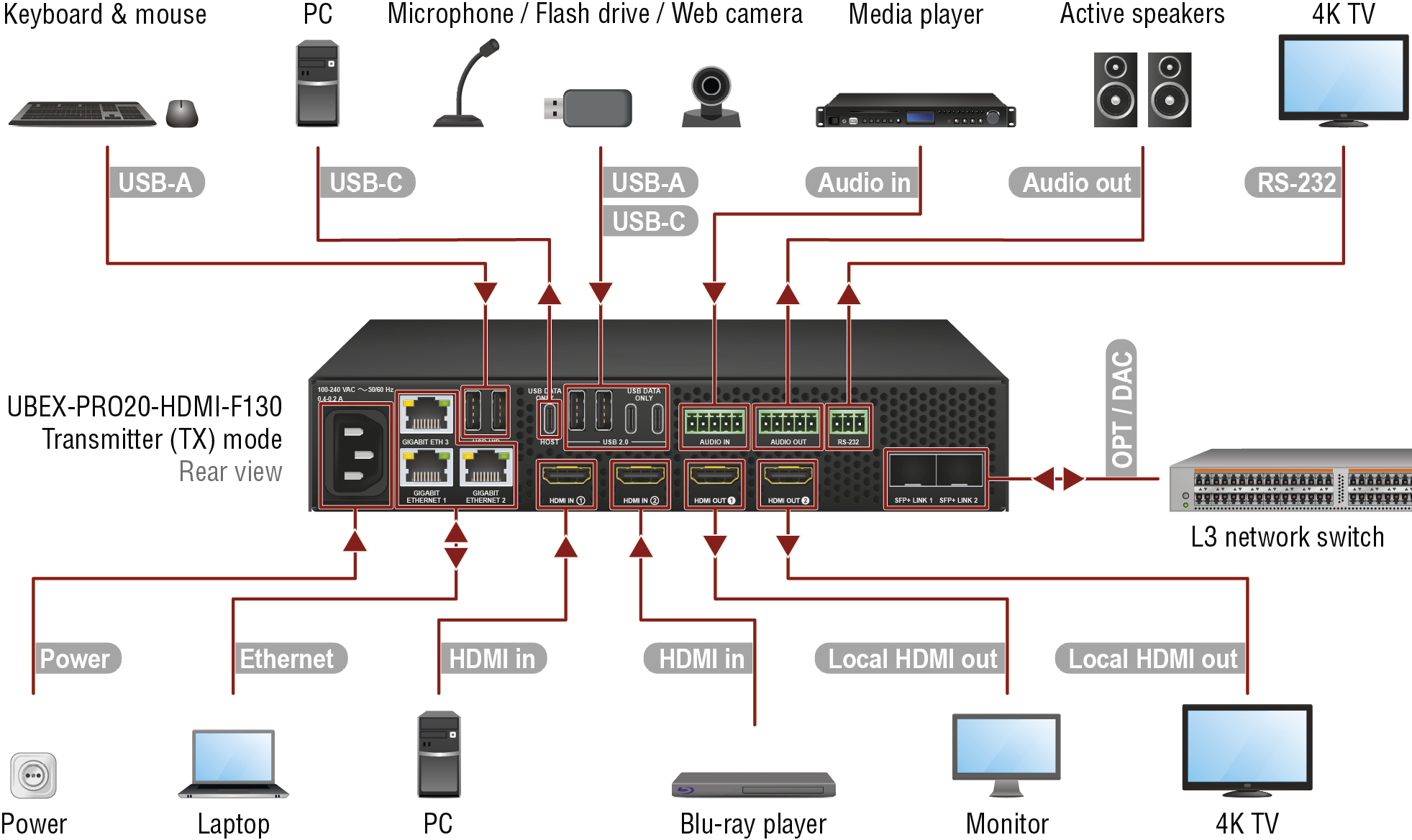
Connections for the F130 model in transmitter operation mode
Changing the Operation Mode
The operation mode of the UBEX endpoint device can be changed using the following methods.
Before connecting the device to the network and the MMU:
▪via front panel LCD menu;
After connecting the device to the network and the MMU:
▪via Lightware Device Controller (LDC) software - see the details in the Device Map section;
▪via LW3 protocol command - see the details in the Set the Operation Mode section.
|
For all F-series models |
|
Connect singlemode or multimode (depends on the installed SFP+ modules) fiber optical cables or DAC cables between the transmitter and the Layer 3 (L3) network switch. The Matrix Mode is detected and applied automatically in the device once the MMU claims the endpoint. |
|
|
|
Connect the source devices (e.g. PC, Blu-ray player) using the HDMI input 1 and 2 ports by HDMI cables. |
||
|
|
Connect the local sink devices (e.g. monitor, 4K TV) to the HDMI output 1 and 2 ports by HDMI cables. |
||
|
|
Optionally connect the transmitter to a LAN in order to control the device. |
||
|
|
Connect the power adaptor to the AC input on the transmitter first, then to the AC power socket. |
||
|
For F111, F121 and F130 models only |
|
Connect an audio source device (e.g. media player) to the audio input connector. |
|
|
|
Connect an audio sink device (e.g. active speakers) to the audio output connector. |
||
|
|
Optionally for RS-232 extension: connect the controlled unit (e.g. 4K TV) to the RS-232 port of the device with a serial cable. |
||
|
For F121 and F130 models only |
|
Optionally for USB HID extension: connect the transmitter to the computer by a USB-C cable. |
|
|
|
Optionally for USB HID extension: connect the USB HID devices to the transmitter (preferably mouse and keyboard). |
||
|
For F130 model only |
|
USB 2.0 ports: connect the USB devices (e.g. microphone, flash drive, web camera, etc) to the extender for the USB 2.0 extension. |
WARNING!User Ethernet is also transmitted over the SFP+ interface, so be sure not to create a network loop.
INFO:The HDMI output ports can be used as local output ports only when the device is configured as transmitter.
5.6.2. F-series Endpoints - Receiver Operation Mode
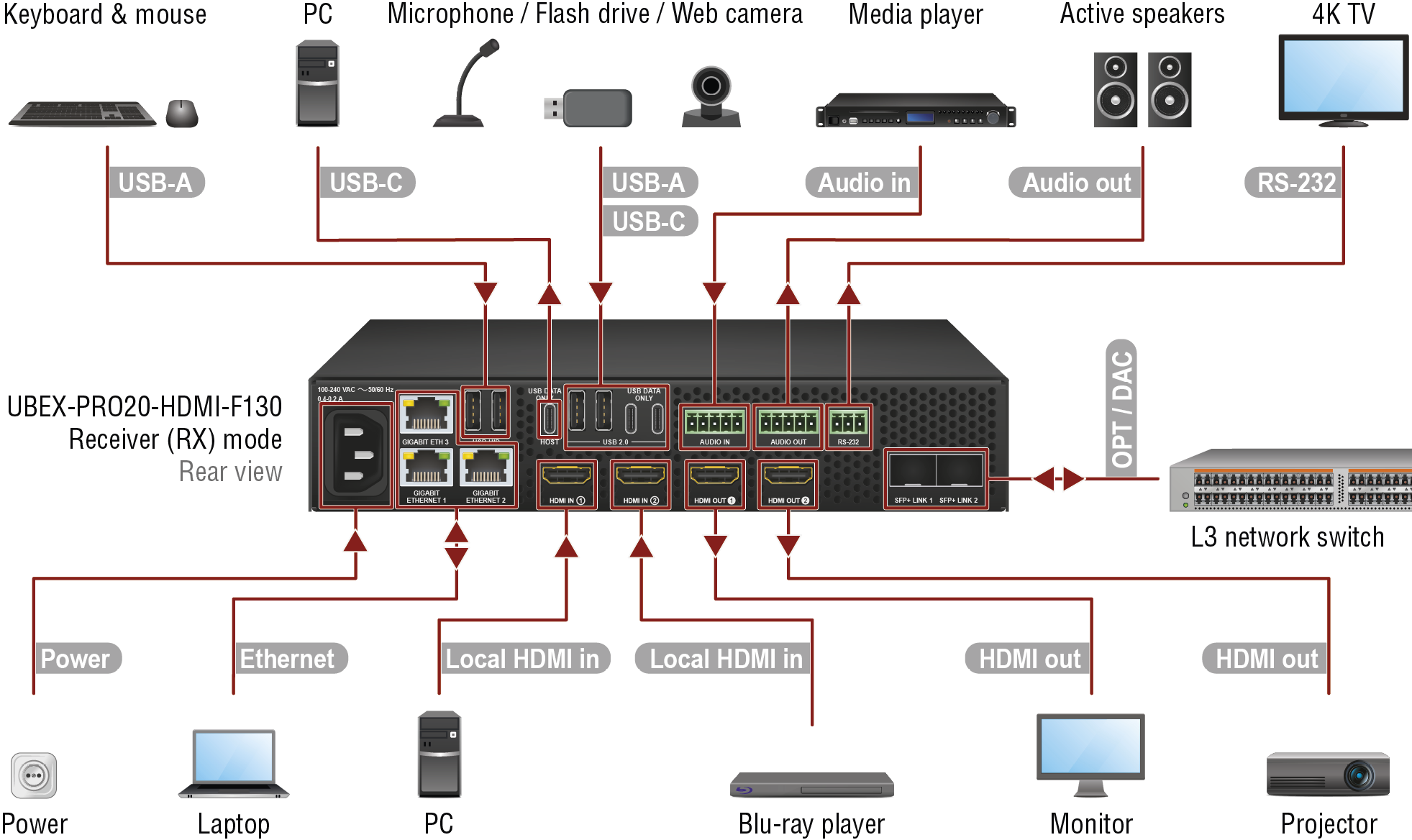
Connections for the F130 model in receiver operation mode
Changing the Operation Mode
The operation mode of the UBEX endpoint device can be changed using the following methods.
Before connecting the device to the network and the MMU:
▪via front panel LCD menu;
After connecting the device to the network and the MMU:
▪via Lightware Device Controller (LDC) software - see the details in the Device Map section;
▪via LW3 protocol command - see the details in the Set the Operation Mode section.
|
For all F-series models |
|
Connect singlemode or multimode (depends on the installed SFP+ modules) fiber optical cables or DAC cables between the receiver and the Layer 3 (L3) network switch. The Matrix Mode is detected and applied automatically in the device once the MMU claims the endpoint. |
|
|
|
Connect the local source devices (e.g. PC, Blu-ray player) using the HDMI input 1 and 2 ports by HDMI cables. |
||
|
|
Connect the sink devices (e.g. monitor, projector) to the HDMI output 1 and 2 ports by HDMI cables. |
||
|
|
Optionally connect the receiver to a LAN in order to control the device. |
||
|
|
Connect the power adaptor to the AC input on the receiver first, then to the AC power socket. |
||
|
For F111, F121 and F130 models only |
|
Connect an audio source device (e.g. media player) to the audio input connector. |
|
|
|
Connect an audio sink device (e.g. active speakers) to the audio output connector. |
||
|
|
Optionally for RS-232 extension: connect the controlled unit (e.g. 4K TV) to the RS-232 port of the device with a serial cable. |
||
|
For F121 and F130 models only |
|
Optionally for USB HID extension: connect the transmitter to the computer by a USB-C cable. |
|
|
|
Optionally for USB HID extension: connect the USB HID devices to the transmitter (preferably mouse and keyboard). |
||
|
For F130 model only |
|
USB 2.0 ports: connect the USB devices (e.g. microphone, flash drive, web camera, etc) to the extender for the USB 2.0 extension. |
WARNING!User Ethernet is also transmitted over the SFP+ interface, so be sure not to create a network loop.
INFO:The HDMI input ports can be used as local input ports only when the device is configured as receiver.
5.6.3. F-series Endpoints - Transceiver Operation Mode
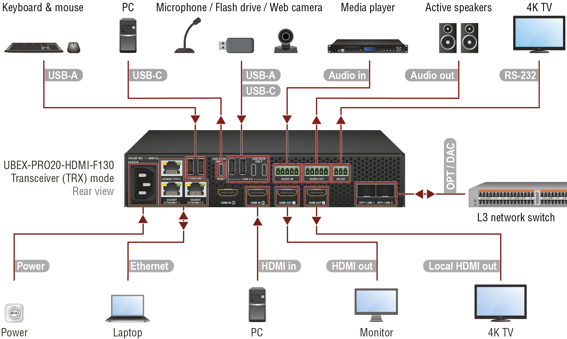
Connections for the F130 model in transceiver operation mode
Changing the Operation Mode
The operation mode of the UBEX endpoint device can be changed using the following methods.
Before connecting the device to the network and the MMU:
▪via front panel LCD menu;
After connecting the device to the network and the MMU:
▪via Lightware Device Controller (LDC) software - see the details in the Device Map section;
▪via LW3 protocol command - see the details in the Set the Operation Mode section.
|
For all F-series models |
|
Connect singlemode or multimode (depends on the installed SFP+ modules) fiber optical cables or DAC cables between the transceiver and the Layer 3 (L3) network switch. The Matrix Mode is detected and applied automatically in the device once the MMU claims the endpoint. |
|
|
|
Connect the source device (e.g. PC) using the HDMI input 2 port by an HDMI cable. |
||
|
|
Connect a sink device (e.g. monitor) to the HDMI output 1 port by an HDMI cable. |
||
|
|
Connect a local sink device (e.g. 4K TV) to the HDMI output 2 port by an HDMI cable. |
||
|
|
Optionally connect the transceiver to a LAN in order to control the device. |
||
|
|
Connect the power adaptor to the AC input on the transceiver first, then to the AC power socket. |
||
|
For F111, F121 and F130 models only |
|
Connect an audio source device (e.g. media player) to the audio input connector. |
|
|
|
Connect an audio sink device (e.g. active speakers) to the audio output connector. |
||
|
|
Optionally for RS-232 extension: connect the controlled unit (e.g. 4K TV) to the RS-232 port of the device with a serial cable. |
||
|
For F121 and F130 models only |
|
Optionally for USB HID extension: connect the transmitter to the computer by a USB-C cable. |
|
|
|
Optionally for USB HID extension: connect the USB HID devices to the transmitter (preferably mouse and keyboard). |
||
|
For F130 model only |
|
USB 2.0 ports: connect the USB devices (e.g. microphone, flash drive, web camera, etc) to the extender for the USB 2.0 extension. |
WARNING!User Ethernet is also transmitted over the SFP+ interface, so be sure not to create a network loop.
INFO:The HDMI input 1 port cannot accept AV signal when the device is configured as transceiver.
5.6.4. F-series Endpoints - Multiviewer Operation Mode
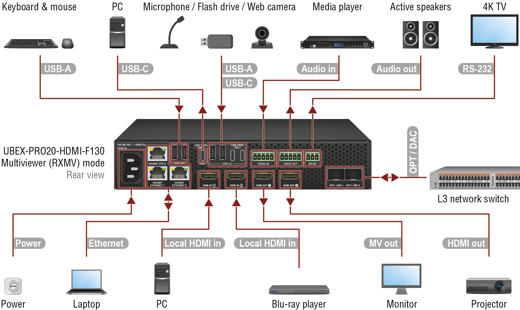
Connections for the F130 model in multiviewer operation mode
Changing the Operation Mode
The operation mode of the UBEX endpoint device can be changed using the following methods.
Before connecting the device to the network and the MMU:
▪via front panel LCD menu;
After connecting the device to the network and the MMU:
▪via Lightware Device Controller (LDC) software - see the details in the Device Map section;
▪via LW3 protocol command - see the details in the Set the Operation Mode section.
DIFFERENCE:The multiviewer operation mode for the endpoint devices is available only from endpoint firmware package v3.2.0 without MMU support. The MMU support is available from MMU firmware package v2.2.0 which includes the endpoint firmware package v3.3.1 for the centralized firmware update.
|
For all F-series models |
|
Connect singlemode or multimode (depends on the installed SFP+ modules) fiber optical cables or DAC cables between the multiviewer and the Layer 3 (L3) network switch. The Matrix Mode is detected and applied automatically in the device once the MMU claims the endpoint. |
|
|
|
Connect the local source devices (e.g. PC, Blu-ray player) using the HDMI input 1 and 2 ports by HDMI cables. |
||
|
|
Connect the multiviewer sink device (e.g. monitor) to the HDMI output 1 port by an HDMI cable. |
||
|
|
Connect a sink device (e.g. projector) to the HDMI output 2 port by an HDMI cable. |
||
|
|
Optionally connect the multiviewer to a LAN in order to control the device. |
||
|
|
Connect the power adaptor to the AC input on the receiver first, then to the AC power socket. |
||
|
For F111, F121 and F130 models only |
|
Connect an audio source device (e.g. media player) to the audio input connector. |
|
|
|
Connect an audio sink device (e.g. active speakers) to the audio output connector. |
||
|
|
Optionally for RS-232 extension: connect the controlled unit (e.g. 4K TV) to the RS-232 port of the device with a serial cable. |
||
|
For F121 and F130 models only |
|
Optionally for USB HID extension: connect the transmitter to the computer by a USB-C cable. |
|
|
|
Optionally for USB HID extension: connect the USB HID devices to the transmitter (preferably mouse and keyboard). |
||
|
For F130 model only |
|
USB 2.0 ports: connect the USB devices (e.g. microphone, flash drive, web camera, etc) to the extender for the USB 2.0 extension. |
WARNING!User Ethernet is also transmitted over the SFP+ interface, so be sure not to create a network loop.
INFO:The HDMI input ports can be used as local input ports only when the device is configured as multiviewer.
5.6.5. F110 / F120 Model - USB K+M and Infrared Connections
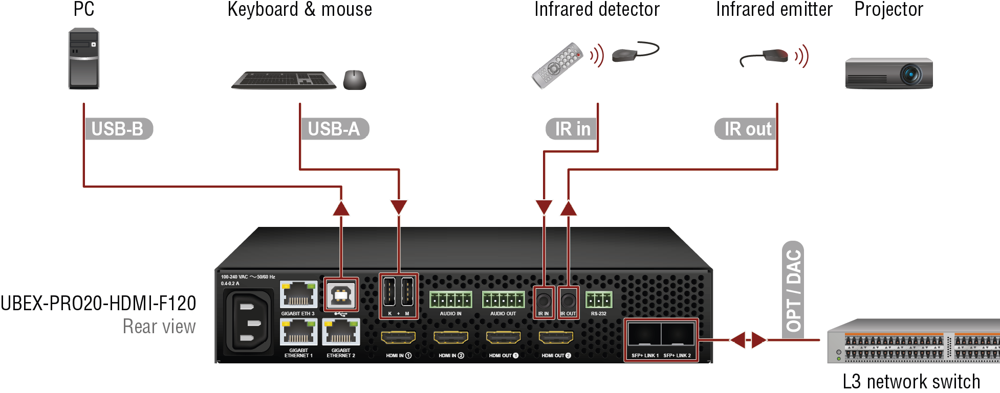
Connections for the F120 model
INFO:The HDMI-, analog audio-, RS-232-, Ethernet-, SFP+ and power-related connections of the F110 and F120 models are the same as the F100 / F111 / F121 / F130 models.
Changing the Mode of the USB HID Ports
The operation mode of the USB HID ports (Local or Remote mode) can be changed using the following methods:
▪via Lightware Device Controller (LDC) software - see the details in the Crosspoint Menu - USB Layer section;
▪via LW3 protocol command - see the details in the Switching the Emulated Port to One Destination and the Switching the Local Emulated Port to the Local Destination sections.
|
For F110 and F120 models |
|
Connect singlemode or multimode (depends on the installed SFP+ modules) fiber optical cables or DAC cables between the multiviewer and the Layer 3 (L3) network switch. The Matrix Mode is detected and applied automatically in the device once the MMU claims the endpoint. |
|
|
|
Connect an Infrared detector unit to the IR IN connector for receiving Infrared input signal. |
||
|
|
Connect an Infrared emitter unit to the IR OUT connector for controlling third-party devices over Infrared signal. |
||
|
For F120 model only |
|
Optionally for USB HID extension: connect the multiviewer to the computer by the USB-B cable. |
|
|
|
Optionally for USB HID extension: connect the USB HID devices to the multiviewer (preferably mouse and keyboard). |
5.6.6. R-series Endpoints - Transmitter Operation Mode
2xMM-2xDUO and 2xSM-2xDUO
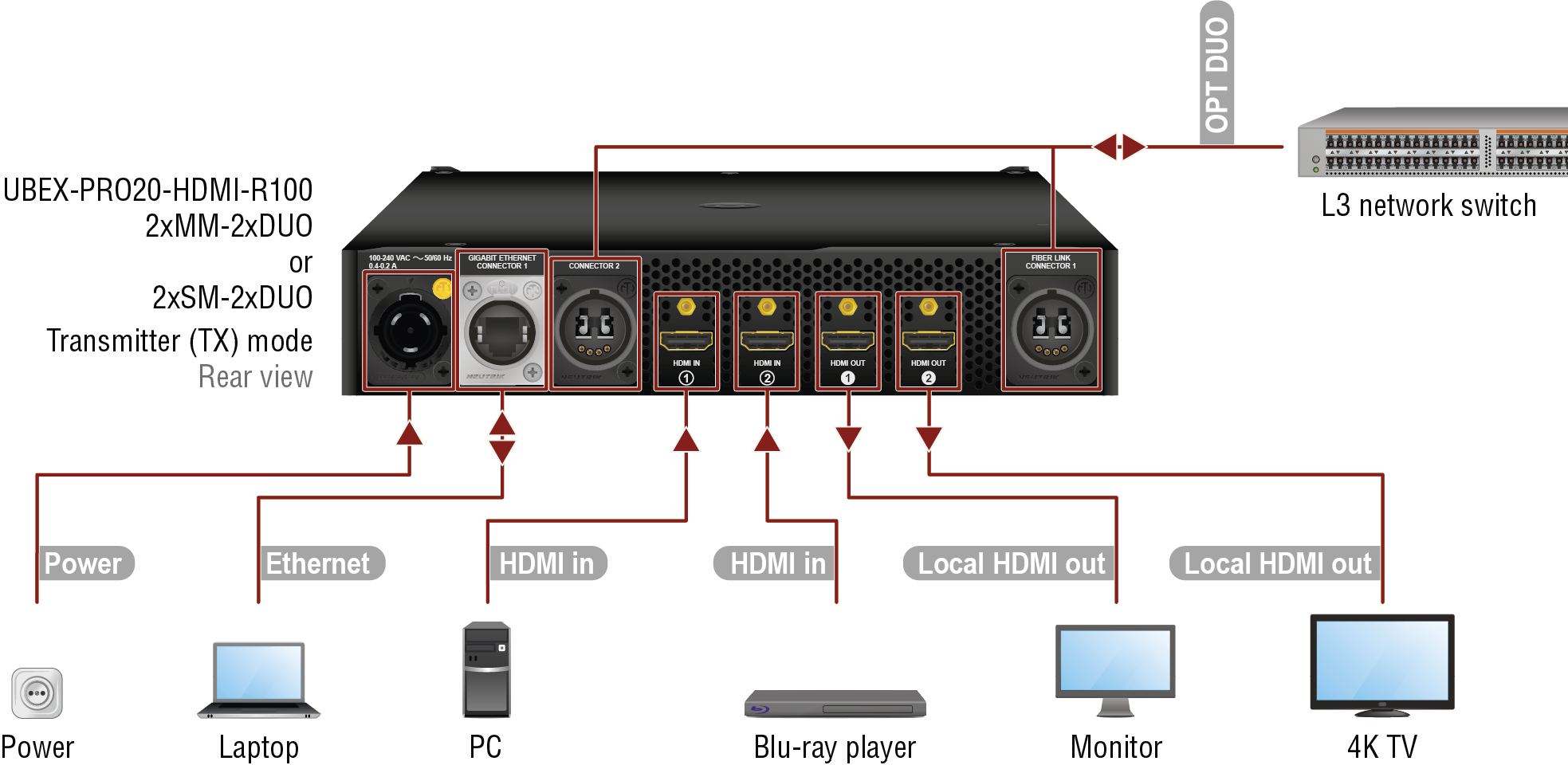
2xMM-QUAD and 2xSM-QUAD

2xSM-BiDi-DUO
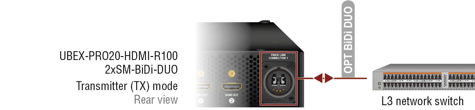
|
For all R-series models |
|
Connect the source devices (e.g. PC, Blu-ray player) using the HDMI input 1 and 2 ports by HDMI cables. |
|
|
|
Connect the local sink devices (e.g. monitor, 4K TV) to the HDMI output 1 and 2 ports by HDMI cables. The ports transmit the original streams of the HDMI input ports. |
||
|
|
Optionally connect the transmitter to a LAN in order to control the device. |
||
|
|
Connect the power adaptor to the AC input on the transmitter first, then to the AC power socket. |
||
|
2xMM-2xDUO |
|
Connect the device and the L3 network switch by 2 pcs multimode Neutrik opticalCON DUO or 4 pcs multimode LC fiber optical cables. * |
|
|
2xMM-QUAD |
|
Connect the device and the L3 network switch by a multimode Neutrik opticalCON QUAD fiber optical cable. * |
|
|
2xSM-2xDUO |
|
Connect the device and the L3 network switch by 2 pcs singlemode Neutrik opticalCON DUO or 4 pcs singlemode LC fiber optical cables. * |
|
|
2xSM-QUAD |
|
Connect the device and the L3 network switch by a singlemode Neutrik opticalCON QUAD fiber optical cable. * |
|
|
2xSM-BiDi-DUO |
|
Connect the device and the L3 network switch by a singlemode Neutrik opticalCON DUO BiDi or 2 pcs singlemode LC fiber optical cables. * The connector does not support the Neutrik opticalCON cross cable. Please use standard cable only. |
WARNING!User Ethernet is also transmitted over the fiber optical interface, so be sure not to create a network loop.
INFO:The HDMI output ports can be used as local output ports only when the device is configured as transmitter.
* You can find more information about the cabling between the switch the R-series endpoint devices in the Connection between the Switch and R-series Endpoints section.
5.6.7. R-series Endpoints - Receiver Operation Mode
2xMM-2xDUO and 2xSM-2xDUO
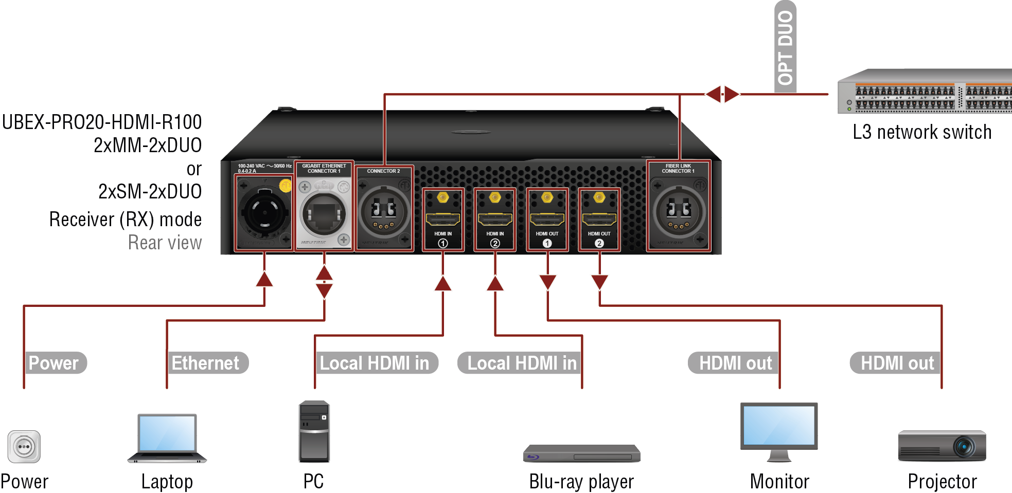
2xMM-QUAD and 2xSM-QUAD
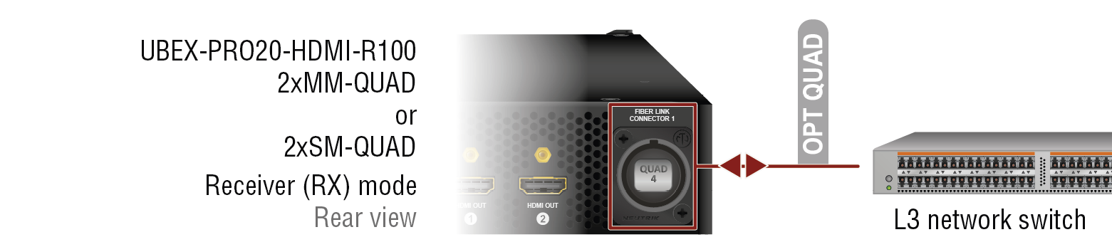
2xSM-BiDi-DUO
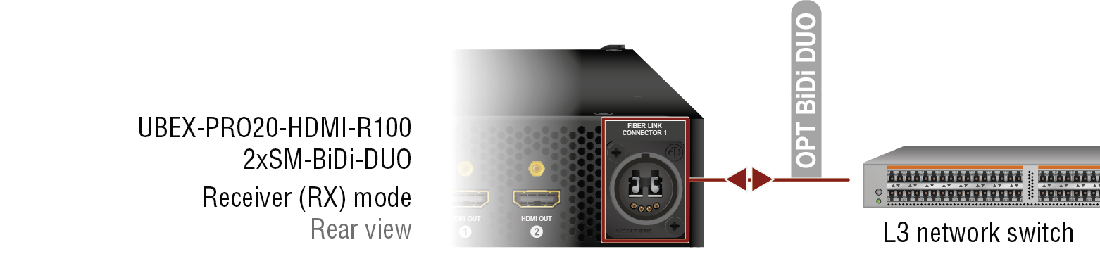
|
For all R-series models |
|
Connect the local source devices (e.g. PC, Blu-ray player) using the HDMI input 1 and 2 ports by HDMI cables. |
|
|
|
Connect the sink devices (e.g. monitor, projector) to the HDMI output 1 and 2 ports by HDMI cables. |
||
|
|
Optionally connect the receiver to a LAN in order to control the device. |
||
|
|
Connect the power adaptor to the AC input on the receiver first, then to the AC power socket. |
||
|
2xMM-2xDUO |
|
Connect the device and the L3 network switch by 2 pcs multimode Neutrik opticalCON DUO or 4 pcs multimode LC fiber optical cables. * |
|
|
2xMM-QUAD |
|
Connect the device and the L3 network switch by a multimode Neutrik opticalCON QUAD fiber optical cable. * |
|
|
2xSM-2xDUO |
|
Connect the device and the L3 network switch by 2 pcs singlemode Neutrik opticalCON DUO or 4 pcs singlemode LC fiber optical cables. * |
|
|
2xSM-QUAD |
|
Connect the device and the L3 network switch by a singlemode Neutrik opticalCON QUAD fiber optical cable. * |
|
|
2xSM-BiDi-DUO |
|
Connect the device and the L3 network switch by a singlemode Neutrik opticalCON DUO BiDi or 2 pcs singlemode LC fiber optical cables. * The connector does not support the Neutrik opticalCON cross cable. Please use standard cable only. |
WARNING!User Ethernet is also transmitted over the fiber optical interface, so be sure not to create a network loop.
INFO:The HDMI input ports can be used as local input ports only when the device is configured as receiver.
* You can find more information about the cabling between the switch the R-series endpoint devices in the Connection between the Switch and R-series Endpoints section.
5.6.8. R-series Endpoints - Transceiver Operation Mode
2xMM-2xDUO and 2xSM-2xDUO
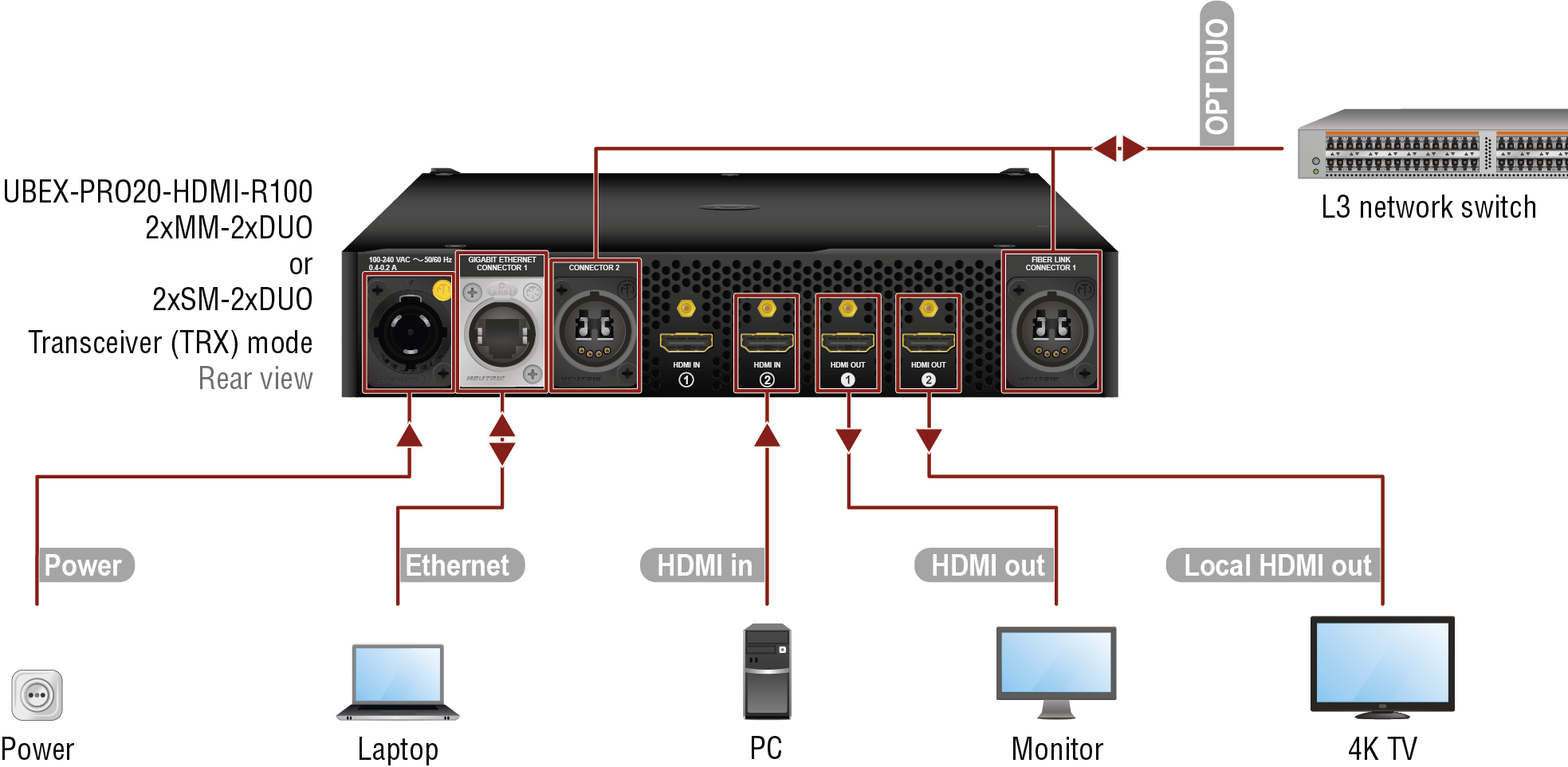
2xMM-QUAD and 2xSM-QUAD
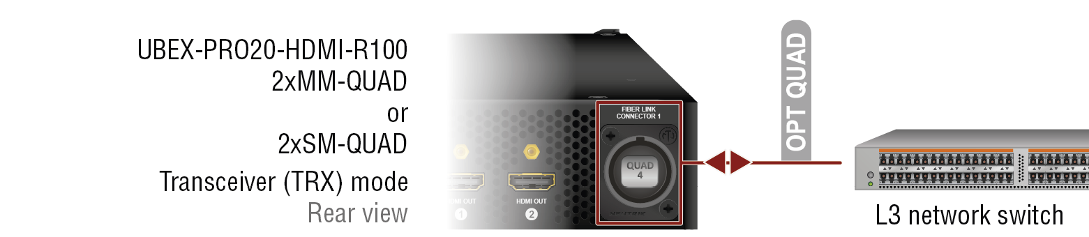
2xSM-BiDi-DUO
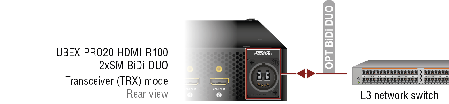
|
For all R-series models |
|
Connect the source device (e.g. PC) using the HDMI input 2 port by an HDMI cable. |
|
|
|
Connect a sink device (e.g. monitor) to the HDMI output 1 port by an HDMI cable. |
||
|
|
Connect a local sink device (e.g. 4K TV) to the HDMI output 2 port by an HDMI cable. The port transmit the original stream of the HDMI in 2 port. |
||
|
|
Optionally connect the transceiver to a LAN in order to control the device. |
||
|
|
Connect the power adaptor to the AC input on the transceiver first, then to the AC power socket. |
||
|
2xMM-2xDUO |
|
Connect the device and the L3 network switch by 2 pcs multimode Neutrik opticalCON DUO or 4 pcs multimode LC fiber optical cables. * |
|
|
2xMM-QUAD |
|
Connect the device and the L3 network switch by a multimode Neutrik opticalCON QUAD fiber optical cable. * |
|
|
2xSM-2xDUO |
|
Connect the device and the L3 network switch by 2 pcs singlemode Neutrik opticalCON DUO or 4 pcs singlemode LC fiber optical cables. * |
|
|
2xSM-QUAD |
|
Connect the device and the L3 network switch by a singlemode Neutrik opticalCON QUAD fiber optical cable. * |
|
|
2xSM-BiDi-DUO |
|
Connect the device and the L3 network switch by a singlemode Neutrik opticalCON DUO BiDi or 2 pcs singlemode LC fiber optical cables. * The connector does not support the Neutrik opticalCON cross cable. Please use standard cable only. |
WARNING!User Ethernet is also transmitted over the fiber optical interface, so be sure not to create a network loop.
INFO:The HDMI input 1 port cannot accept AV signal when the device is configured as transceiver.
* You can find more information about the cabling between the switch the R-series endpoint devices in the Connection between the Switch and R-series Endpoints section.
5.6.9. R-series Endpoints - Multiviewer Operation Mode
2xMM-2xDUO and 2xSM-2xDUO
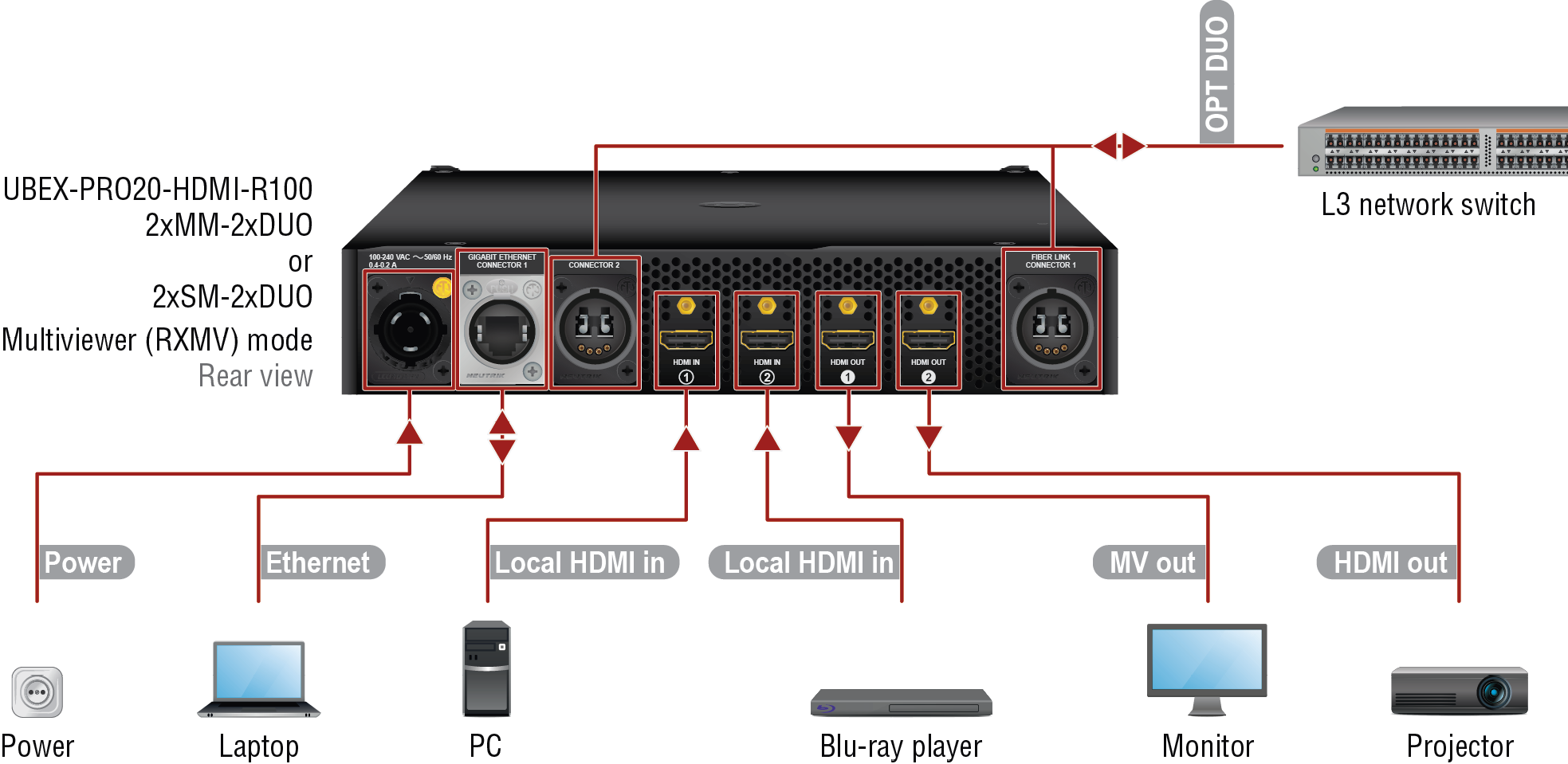
2xMM-QUAD and 2xSM-QUAD
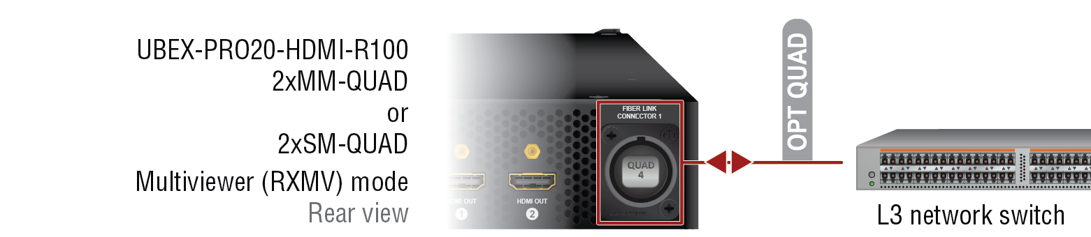
2xSM-BiDi-DUO
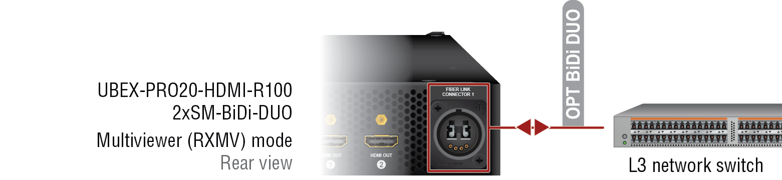
|
For all R-series models |
|
Connect the local source devices (e.g. PC, Blu-ray player) using the HDMI input 1 and 2 ports by HDMI cables. |
|
|
|
Connect the multiviewer sink device (e.g. monitor) to the HDMI output 1 port by an HDMI cable. |
||
|
|
Connect a sink device (e.g. projector) to the HDMI output 2 port by an HDMI cable. |
||
|
|
Optionally connect the multivivewer to a LAN in order to control the device. |
||
|
|
Connect the power adaptor to the AC input on the multivivewer first, then to the AC power socket. |
||
|
2xMM-2xDUO |
|
Connect the device and the L3 network switch by 2 pcs multimode Neutrik opticalCON DUO or 4 pcs multimode LC fiber optical cables. * |
|
|
2xMM-QUAD |
|
Connect the device and the L3 network switch by a multimode Neutrik opticalCON QUAD fiber optical cable. * |
|
|
2xSM-2xDUO |
|
Connect the device and the L3 network switch by 2 pcs singlemode Neutrik opticalCON DUO or 4 pcs singlemode LC fiber optical cables. * |
|
|
2xSM-QUAD |
|
Connect the device and the L3 network switch by a singlemode Neutrik opticalCON QUAD fiber optical cable. * |
|
|
2xSM-BiDi-DUO |
|
Connect the device and the L3 network switch by a singlemode Neutrik opticalCON DUO BiDi or 2 pcs singlemode LC fiber optical cables. * The connector does not support the Neutrik opticalCON cross cable. Please use standard cable only. |
WARNING!User Ethernet is also transmitted over the fiber optical interface, so be sure not to create a network loop.
DIFFERENCE:The multiviewer operation mode for the endpoint devices is available only from endpoint firmware package v3.2.0 without MMU support. The MMU support is available from MMU firmware package v2.2.0 which includes the endpoint firmware package v3.3.1 for the centralized firmware update.
INFO:The HDMI input ports can be used as local input ports only when the device is configured as multiviewer.
* You can find more information about the cabling between the switch the R-series endpoint devices in the Connection between the Switch and R-series Endpoints section.
5.6.10. Matrix Management Unit (MMU)
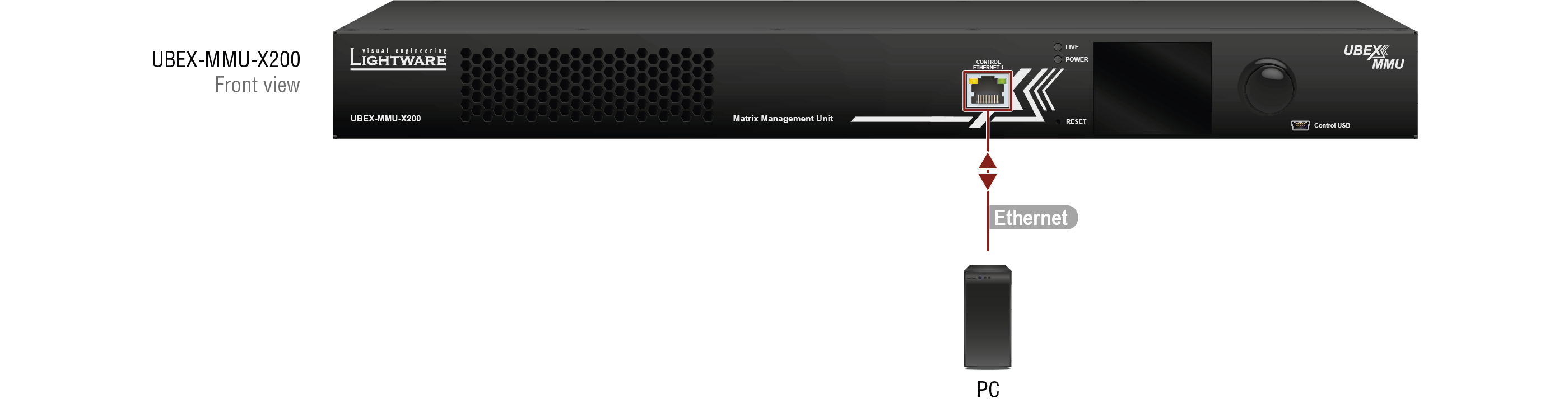
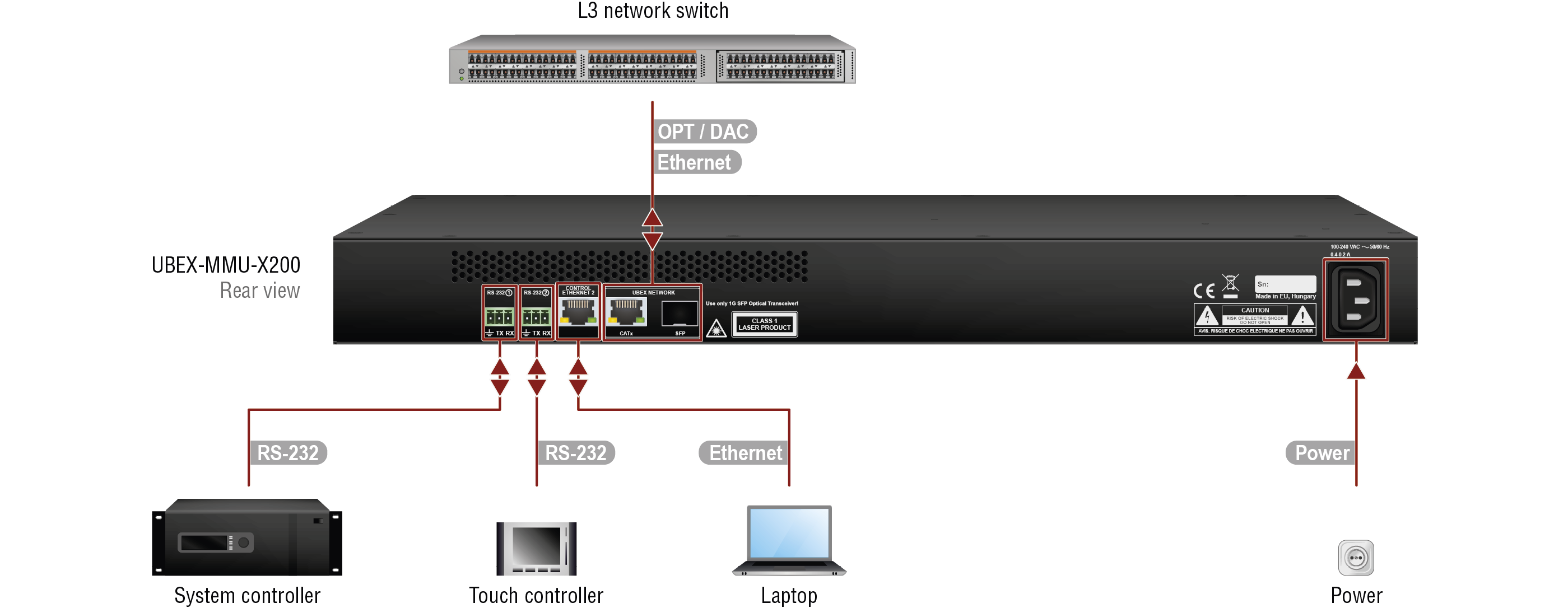
Connections for the UBEX-MMU-X200 Matrix Management Unit
|
|
Two possibilities are available to connect the MMU to the Layer 3 (L3) network switch: ▪via Ethernet: use the CATx port of the UBEX Network for the Ethernet connection between the devices, OR ▪via SFP port: –use a singlemode or multimode (depends on the installed SFP (not SFP+) modules) fiber optical cables or DAC cables between the MMU and the Layer 3 (L3) network switch. –use CATx cable between the MMU and the Layer 3 (L3) network switch when RJ45 SFP (not SFP+) module is installed to the slot. |
|
|
Connect a controller device (e.g. PC, laptop) to the MMU with a CATx cable for the connection to the LAN network. |
|
|
Optionally connect third-party controller devices (e.g. system controller, touch controller) with a serial cable via the RS-232 1 and 2 connectors. |
|
|
Connect the power adaptor to the AC input on the MMU first, then to the AC power socket. |
ATTENTION!Pay attention that the rear panel Ethernet connector supports 1 Gbps, the front panel Ethernet connector supports 100 Mbps Ethernet connection.
INFO:The USB control function will be added by future firmware update.
5.7. SFP / SFP+ Slot Connection
INFO:The SFP / SFP+ slots support the Plug and Play connection which means UBEX devices do not need to be powered off before inserting or removing SFP / SFP+ modules or DAC cables.
5.7.1. Installation of SFP / SFP+ Modules
Endpoint Devices
UBEX endpoint devices use SFP+ modules for the fiber optical connections. The optical modules can be changed based on the recent application of the extender: it can be singlemode or multimode, or BiDi modules, up to 10 GbE signal transmission.
INFO:It is recommended to install 2x 10 GbE SFP+ modules per endpoint in the case of HDMI 2.0 (4K@60 Hz 4:4:4) signal transmission.
Matrix Management Unit
The UBEX-MMU-X200 Matrix Management Unit has one SFP module slot for the fiber optical connection via the network switch.
ATTENTION!The SFP port slot can handle SFP module up to 1 GbE support.
Inserting and Cabling of SFP / SFP+ Modules
Step 1.Put up on the handle bar.
Step 2.Connect the module to the to one of the SFP / SFP+ port slot.
Step 3.Connect the LC connectors / RJ45 Ethernet cables to the SFP / SFP+ modules.
INFO:The SFP / SFP+ modules have a side that clips to the connector on the port of the switch, and is designed to prevent the module from being inserted the wrong way into the port. Do NOT force module into the port.
Removing SFP / SFP+ Modules
Step 1.Disconnect the LC connectors / RJ45 Ethernet cables from the SFP / SFP+ module.
Step 2.Pull down on the handle bar.
Step 3.Gently slide out the SFP / SFP+ module from the slot.
5.7.2. Installation of DAC Cables
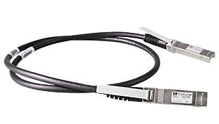
Endpoint Devices
UBEX endpoints can be connected via DAC (Direct Attach Copper) cables to the network switch. The cable type must support 10 GbE signal transmission.
INFO:It is recommended to install 2x 10 GbE DAC cables in the case of HDMI 2.0 (4K@60 Hz 4:4:4) signal transmission.
Matrix Management Unit
The UBEX-MMU-X200 Matrix Management Unit can be connected via DAC (Direct Attach Copper) cables to the network switch.
ATTENTION!The SFP port slot can handle SFP module up to 1 GbE support.
Inserting the DAC Cables
Step 1.Push the plug of the DAC cable to one of the SFP / SFP+ port slot of the transmitter to stop.
Step 2.Push the other plug of the DAC cable to one of the SFP / SFP+ port slot of the receiver to stop.
Removing the DAC Cables
Pull the handle bar of the plug and gently slide out the cable from the slot.
INFO:See more details about the SFP / SFP+ interfaces in the SFP / SFP+ Interfaces section.
5.8. Fiber Optical Cable Connections
The section describes how to connect the fiber optical cables between two SFP+ modules or between two Neutrik opticalCON connectors in case of F and R-series endpoint devices.
5.8.1. Connection between SFP+ Modules
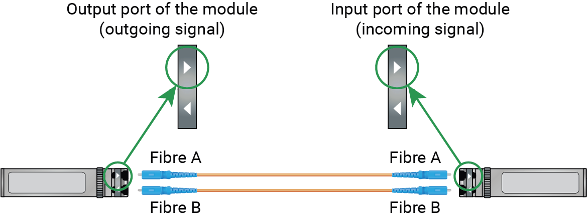
Affected models:
▪UBEX-PRO20-HDMI-F100
▪UBEX-PRO20-HDMI-F110
▪UBEX-PRO20-HDMI-F111
▪UBEX-PRO20-HDMI-F120
▪UBEX-PRO20-HDMI-F121
▪UBEX-PRO20-HDMI-F130
Connect multimode or singlemode fiber optical cables with LC simplex connectors to the SFP+ modules like in the illustration on the right.
ATTENTION!Always check the direction of the optical signal. The TX port of the module is higlighted with an arrow pointing outward from the device, the RX port of the module is higlighted with another arrow pointing inward to the device.
5.8.2. Connection between BiDi (Bidirectional) SFP+ Modules
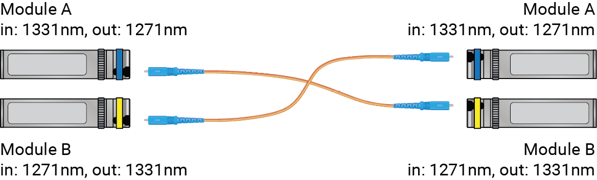
Affected models:
▪UBEX-PRO20-HDMI-F100
▪UBEX-PRO20-HDMI-F110
▪UBEX-PRO20-HDMI-F111
▪UBEX-PRO20-HDMI-F120
▪UBEX-PRO20-HDMI-F121
▪UBEX-PRO20-HDMI-F130
Connect multimode or singlemode fiber optical cables with LC simplex connectors to the BiDi SFP+ modules like in the illustration on the right.
ATTENTION!The Module A must be connected to the Module B. Always check the wavelength of the BiDi modules. If the wavelengths are different, the cabling might be also different and the modules shall be connected across.
5.8.3. Connection between Neutrik opticalCON DUO Connectors
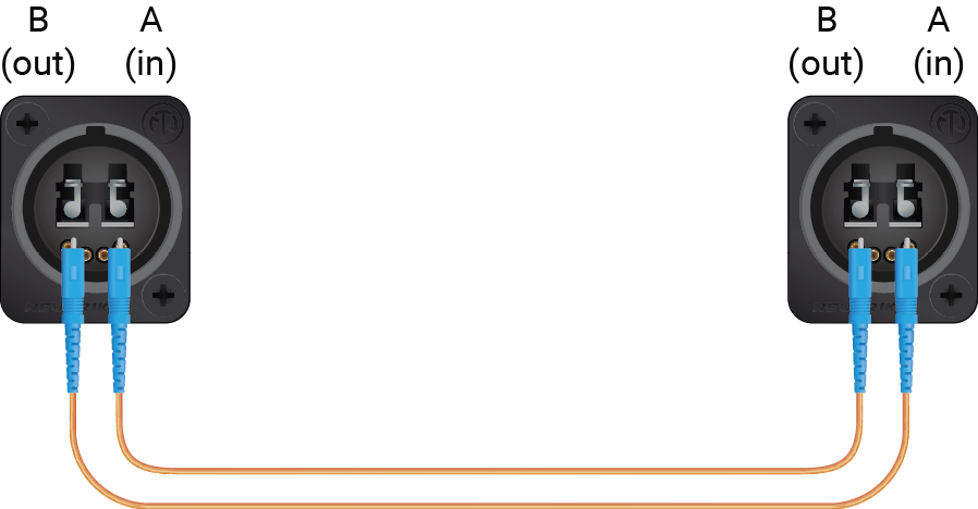
Affected models:
▪UBEX-PRO20-HDMI-R100 2xMM-2xDUO
▪UBEX-PRO20-HDMI-R100 2xSM-2xDUO
Connect multimode or singlemode fiber optical cables with LC simplex connectors to the Neutrik opticalCON DUO connectors like in the illustration on the right.
ATTENTION!Always check the direction of the optical signal. The Port A must be connected to the Port B.
5.8.4. Connection between Neutrik opticalCON DUO BiDi Connectors
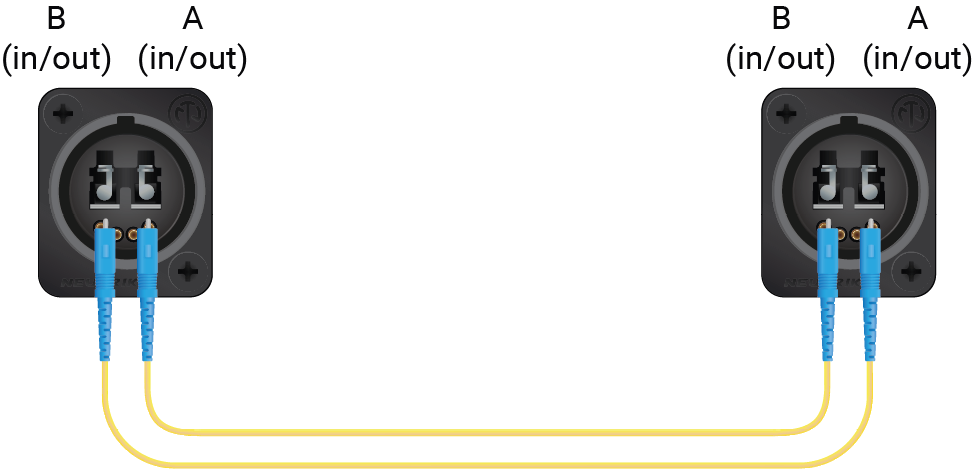
Affected model:
▪UBEX-PRO20-HDMI-R100 2xSM-BiDi-DUO
Connect multimode or singlemode fiber optical cables with LC simplex connectors to the Neutrik opticalCON DUO connectors like in the illustration on the right.
ATTENTION!Always check the direction of the optical signal. The Port A must be connected to the Port B.
5.9. Copper Cable Connections
The section describes how to connect the CATx copper Ethernet cables between two SFP+ to RJ45 modules in case of F-series endpoint devices.
Affected models:
▪UBEX-PRO20-HDMI-F100
▪UBEX-PRO20-HDMI-F110
▪UBEX-PRO20-HDMI-F111
▪UBEX-PRO20-HDMI-F120
▪UBEX-PRO20-HDMI-F121
▪UBEX-PRO20-HDMI-F130
Connect CAT6A or CAT7 (AWG24 or higher category) 10G Ethernet cable to the SFP+ to RJ45 modules.
ATTENTION!Always apply equal length copper cables for both SFP+ to RJ45 modules in case of 20G signal transmission. Different cable lengths may cause data package loss.
INFO:In case of SFP+ to RJ45 module installation, the endpoint device sets the cooling fans to (minimum) 2500 rpm automatically.
TIPS AND TRICKS:AWG number shows the quality of the copper cable. The number is smaller, the quality of the cable is better and its resistance is even smaller. Smaller resistance makes possible applying longer cable.
5.10. Connection between the Switch and R-series Endpoints
L3 network switches are built with SFP+ slots, the R-series devices are built with Neutrik opticalCON DUO and QUAD fiber optical connections. This section is about how to establish connection between the switch and the R-series endpoint devices over the different type of connectors.
5.10.1. SFP+ to Neutrik opticalCON DUO
This method is working with the following endpoint models:
▪UBEX-PRO20-HDMI-R100 2xMM-2xDUO
▪UBEX-PRO20-HDMI-R100 2xSM-2xDUO
Connecting Steps
Step 1.Insert 2 pcs of 10GbE singlemode/multimode SFP+ transceiver modules to the SFP+ slots of the network switch.
Step 2.You need 2 pcs singlemode/multimode Neutrik opticalCON DUO series connectors and 2 pcs of singlemode/multimode fiber optical patch cables with LC duplex connectors. Connect the SFP+ modules and the back of the Neutrik opticalCON DUO connector by the patch cables (a standard LC duplex connector can be found on the back of the Neutrik opticalCON DUO connector).
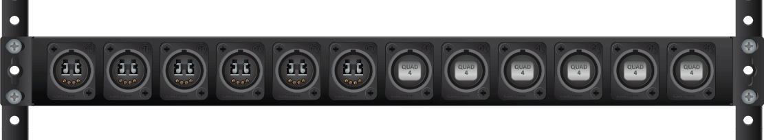
TIPS AND TRICKS:Extra Neutrik connectors can be assembled to a blank 1U high rack shelf which can make the mounting of the connection and the cabling easier.
Step 3.Establish connection between the additional Neutrik opticalCON DUO connectors and the R100 endpoint device using 2 pcs of singlemode/multimode Neutrik opticalCON DUO series cables. The following figure shows the correct cabling layout of optical connectors on the R100 endpoint device:
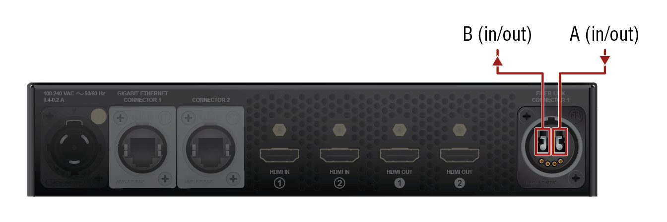
|
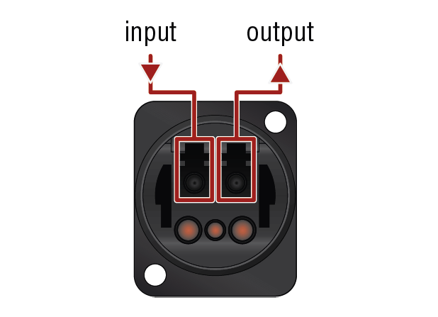
|
|
Layout of the 2xMM-2xDUO / 2xSM-2xDUO models (rear view) |
Layout of the extra connector (rear view) |
ATTENTION!Always be sure that the fiber optical mode of the entire fiber optical equipment (SFP+ modules, LC patch cables, Neutrik connectors, and cables) and R100 endpoint device is the same. Connecting to the 2xMM-2xDUO model requires multimode equipment, connecting to the 2xSM-2xDUO model requires singlemode equipment.
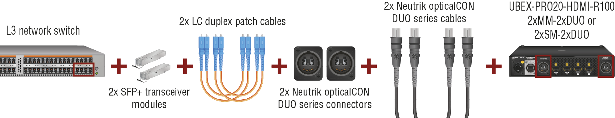
Required fiber optical equipment for connecting the network switch and an R100 DUO endpoint device
INFO:This method does not work in the case of using DAC cables in the network switch.
5.10.2. SFP+ to Neutrik opticalCON QUAD
This method is working with the following endpoint models:
▪UBEX-PRO20-HDMI-R100 2xMM-QUAD
▪UBEX-PRO20-HDMI-R100 2xSM-QUAD
Connecting Steps
Step 1.Insert 2 pcs of 10GbE singlemode/multimode SFP+ transceiver modules to the SFP+ slots of the network switch.
Step 2.You need a singlemode/multimode Neutrik opticalCON QUAD series connector and 2 pcs of singlemode/multimode fiber optical patch cables with LC duplex connectors. Connect the SFP+ modules and the back of the Neutrik opticalCON QUAD connector by the patch cables (2 pcs of standard LC duplex connectors can be found on the back of the Neutrik opticalCON QUAD connector).
TIPS AND TRICKS:Extra Neutrik connectors can be assembled to a blank 1U high rack shelf which can make the mounting of the connection and the cabling easier.
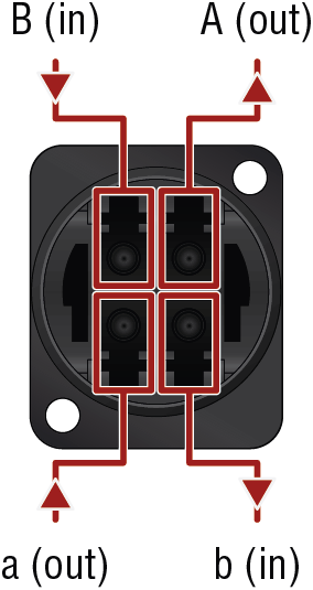
Step 3.Establish connection between the additional Neutrik opticalCON QUAD connector and the R100 endpoint device using a singlemode/multimode Neutrik opticalCON QUAD series cable. The following figure shows the correct cabling layout of the extra QUAD optical connector (the back of the extra connector can be seen on the right).
ATTENTION!Always be sure that the fiber optical mode of the entire fiber optical equipment (SFP+ modules, LC patch cables, Neutrik connectors, and cables) and R100 endpoint device is the same. Connecting to the 2xMM-QUAD model requires multimode equipment, connecting to the 2xSM-QUAD model requires singlemode equipment.
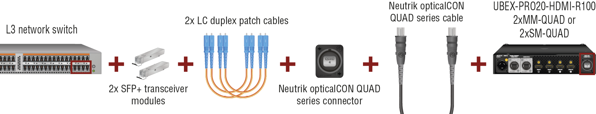
Required fiber optical equipment for connecting the network switch and an R100 QUAD endpoint device
INFO:This method does not work in the case of using DAC cables in the network switch.
5.10.3. SFP+ BiDi to Neutrik opticalCON DUO BiDi
This method is working with the following endpoint model:
▪UBEX-PRO20-HDMI-R100 2xSM-BiDi-DUO
Connecting Steps
Step 1.Insert 2 pcs of 10GbE singlemode SFP+ BiDi transceiver modules to the SFP+ slots of the network switch.
Step 2.You need a singlemode/multimode Neutrik opticalCON DUO BiDi connector and 2 pcs of singlemode/multimode fiber optical patch cables with LC simplex connectors. Connect the SFP+ modules and the back of the Neutrik opticalCON DUO connector by the patch cables (a standard LC duplex connector can be found on the back of the Neutrik opticalCON DUO connector).
TIPS AND TRICKS:Extra Neutrik connectors can be assembled to a blank 1U high rack shelf which can make the mounting of the connection and the cabling easier.
Step 3.Establish connection between the additional Neutrik opticalCON DUO connector and the R100 endpoint device using a singlemode/multimode Neutrik opticalCON DUO BiDi cable. The following figure shows the correct cabling layout of optical connectors on the R100 endpoint device:

|
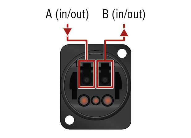
|
|
Layout of the 2xSM-BiDi DUO model (rear view) |
Layout of the extra connector (rear view) |
|
SFP+ modules behind the Neutrik opticalCON DUO connector |
||
|
Channel |
Type of the SFP+ module |
Wavelength |
|
A |
Finisar FTLX2072D327 |
input: 1331 nm; output: 1271 nm |
|
B |
Finisar FTLX2072D333 |
input: 1271 nm; output: 1331 nm |
ATTENTION!The 2xSM-BiDi-DUO model does not support the Neutrik opticalCON DUO cross cables. Please use standard cables only.
ATTENTION!Always be sure that the fiber optical mode of the entire fiber optical equipment (SFP+ modules, LC patch cables, Neutrik connectors, and cables) and R100 endpoint device is the same. Connecting to the 2xSM-BiDi-DUO model requires singlemode equipment.
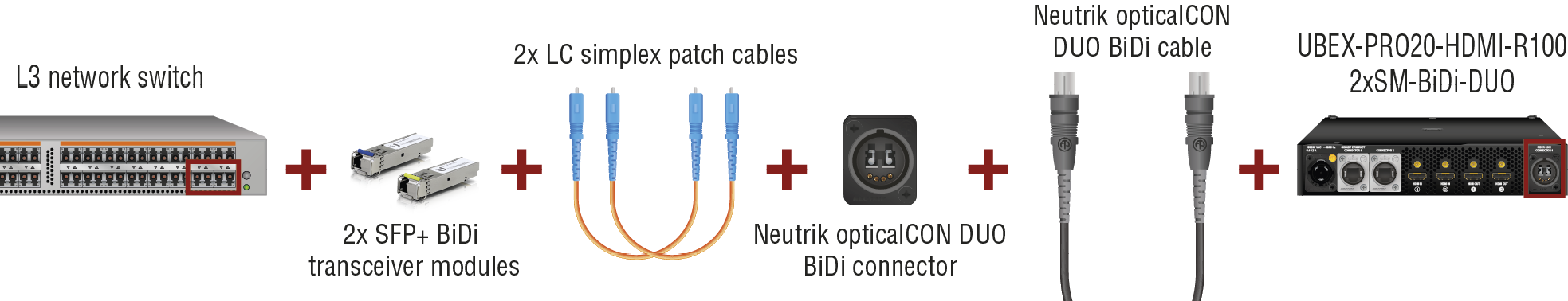
Required fiber optical equipment for connecting the network switch and an R100 2xSM-BiDi-DUO endpoint device
INFO:This method does not work in the case of using DAC cables in the network switch.
5.11. Ethernet Switch - Detailed Requirements
In the virtual matrix architecture a third party switch is used to transfer IP packets. In connection with this switch, the following criteria must be met:
▪10 Gbps non-blocking switch (capable of full bandwidth transmission between all ports)
▪Supports IEEE Std. 802.3ad-2000 Link Aggregation Control Protocol, with Link Aggregation Groups for each endpoint.
▪Supports Internet Group Management Protocol version 2 (RFC 2236) snooping.
▪IPv4 (or Layer 2) Multicast Forwarding based on IGMP v2 snooping, with at least 16 addresses available for each endpoint, e.g. 4096 IPv4 multicast addresses for 256 endpoints.
▪Supports IEEE Std. 802.1Q VLAN tagging: 1 VLAN reserved for UBEX control and media transmission, other(s) available for user traffic.
Optional Requirements:
▪Supports Link Layer Discovery Protocol (LLDP), in order to discover network topology.
ATTENTION!LLDP settings is basically not required to build up a UBEX matrix so it is called optional, however Lightware highly recommends to set up because LLDP is indispensable at the system installation and diagnostics.
▪Supports IEEE Std. 802.1Q (formerly 802.1p) priority code point (PCP), and implements priority based queuing for at least 1 prioritized traffic class. This is required to guarantee uninterrupted media transmission regardless of the user traffic.
▪Supports IEEE Std. 802.1s (merged into IEEE Std. 802.1Q-2005) Multiple Spanning Tree Protocol (MSTP), in order to detect switching loops in VLAN’s.
Installation and Network Guide for UBEX
For more details about requirements of the network switch please visit our website and download the application notes for UBEX:
https://go.lightware.com/guide-for-UBEX
System Design Guide for UBEX
Please check our documentation about the UBEX AV system design. This guide summarizes the network switches of the market and collects the required accessories and costs incurred.
https://go.lightware.com/system-design-guide-for-ubex
5.12. Ethernet Switch Configuration
5.12.1. Link Aggregation (LAG)
DEFINITION:The Link Aggregation Group (LAG) applies to various methods of combining (aggregating) multiple network connections in parallel in order to increase throughput beyond what a single connection could sustain.
Create Link Aggregation Groups (LAG’s)/EtherChannels etc. for each port pair that is used for 20 GbE transmission (LAG is not necessary for the ports which are used for 10 GbE transmission). The bonding mode is dynamic: 802.3-ad LACP has to be enabled for each group.
DEFINITION:A virtual LAN (VLAN) is any broadcast domain that is partitioned and isolated in a computer network at the data link layer (OSI layer 2). LAN is the abbreviation for local area network and in this context, virtual refers to a physical object recreated and altered by additional logic.
The UBEX network uses 802.1Q tagged frames with the VLAN ID of 286. This VLAN has to be available from each LAG, with tagged frames. The LAG’s have to be in trunk mode (multiple VLAN's are available on UBEX devices, other VLAN's may be used with tagged or untagged frames).
The port where the MMU is connected is also a trunk port.
DEFINITION:IGMP snooping is the process of listening to Internet Group Management Protocol network traffic. The feature allows a network switch to listen in on the IGMP conversation between hosts and routers.
IGMPv2 snooping has to be enabled for each LAG in this VLAN.
Enable Link Layer Discovery Protocol (LLDP) on all ports to access topology information in order to speed up your installation process.
5.12.5. Installation and Network Setup Guide for UBEX
For more details about the configuration steps of the network switch, real-life examples and useful practices please visit our website and download the application notes for UBEX:
https://go.lightware.com/guide-for-UBEX
5.12.6. System Design Guide for UBEX
Please check our documentation about the UBEX AV system design. This guide summarizes the network switches of the market and collects the required accessories and costs incurred.
https://go.lightware.com/system-design-guide-for-ubex
5.13. Startup of the System
The following section describes the startup of the UBEX matrix system step-by-step from the beginning to the displayed video on the sink devices.
ATTENTION!Before powering on the system, please check the Connections section to be sure all installation steps are met with the connection requirements.
5.13.1. Switch on the Devices
Power on the network switch, the MMU, all the transmitters and the receivers, the source, and the sink devices as well.
INFO:UBEX endpoints and the MMU do a self-test during the booting procedure. After it is done, the last configuration is loaded automatically.
5.13.2. Configure the Operation Mode
All endpoint devices are manufactured as transmitter (TX) by default. Set up the operation mode for the endpoints to be used as receivers or transceivers with the adequate method:
▪Before connecting the device to the UBEX matrix - use the Front panel LCD menu (System settings / Operation mode submenu).
▪After connecting the device to the UBEX matrix - use the Lightware Device Controller software. See the details in the Device Map section.
5.13.3. Connect to the Matrix Management Unit
Establish the connection between the Matrix Management Unit (MMU) and the controller device. There is three way to connect to the MMU:
▪LAN (Control Ethernet 1 and 2 ports; or via the network switch)
▪Serial communication (RS-232 1 and 2 ports)
ATTENTION!User Ethernet is also transmitted over the SFP+ interface, so be sure not to make a network loop.
INFO:The USB control interface is under development.
INFO:In the case of LAN connection: it does not matter that you connect to the MMU or an endpoint device - finally you will control the MMU in both cases.
Network Settings
Check the network settings of the MMU. You can find the factory default settings of the device in the UBEX-MMU-X200 section. The network settings can be changed using the following method:
▪via LDC software, in the Device discovery window - see the details in the Establishing Connection section.
Lightware Device Controller Software
All required settings can be done by control software, the Lightware Device Controller (LDC). See all the details about it in the Software Control - Lightware Device Controller chapter.
Discovering the MMU
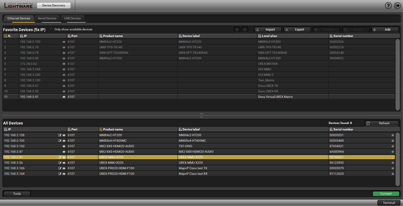
Step 1.Open the LDC software. The Device discovery window will launch automatically to discover all available Lightware devices on the network where the controller device is connected to.
Step 2.Select the MMU (UBEX-MMU-X200) and click on the green Connect button.

TIPS AND TRICKS:When the device discovery found your device but you cannot connect to it, you can set the required IP address by clicking the pencil icon.
5.13.4. Check the Signal Status
The Crosspoint menu in the LDC software displays all important information about your UBEX matrix. For more detailed information, see the Crosspoint Menu - Video Layer section.
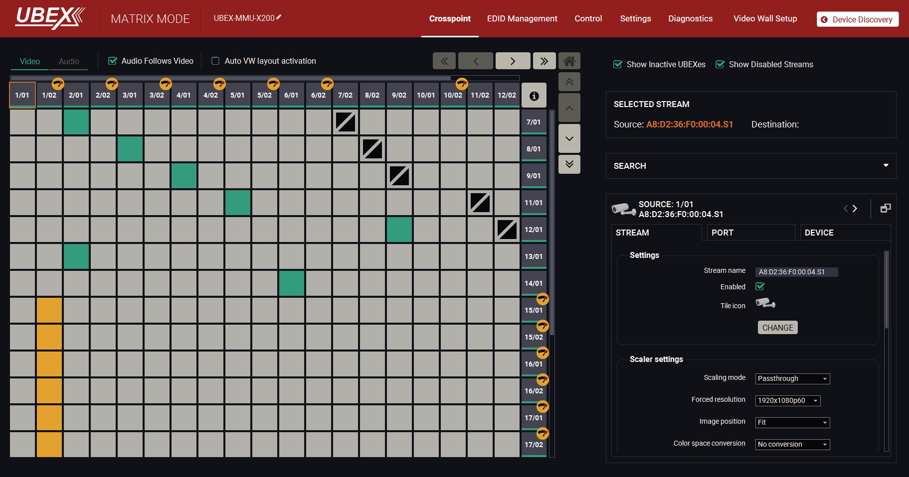
The Crosspoint menu in the LDC software
INFO:You can find more details about the default port numbering and device naming in the Default Naming of the Devices and the Streams section.
Source (Input Stream of a Transmitter or Transceiver) Side

Check the HDMI signal status on the Source ports - if the signal status indicator is green, the signal is present; if it is grey, there is no incoming signal on the port.
Destination (Output Port of a Receiver or Transceiver) Side

Check the HDMI signal status on the Destination ports - if the signal status indicator is green, the signal is present; if it is grey, there is no transmitted signal on the port.
5.13.5. Customize the View of the Matrix

If not all input / output ports of the endpoints are used in your matrix, you can hide the unused ones. Click on the unused source / destination port. Select the Stream tab and remove the tick in the Enabled option. The disabled sources / destinations can be hidden when you disable the Show Disabled Streams option.
5.13.6. Give Unique Names for the Sources and Destinations
INFO:You can find more details about the stream and device naming in the Default Naming of the Devices and the Streams section.
The default name of the streams are generated from the MAC address of the device and a port number of the endpoint. The better recognition of the streams might be helped to give unique names.
Naming of the Streams
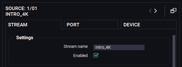
Click on the source / destination port where the stream is transmitted / received. Select the Stream tab and find the Stream name field and type a unique name which can describe the stream well, for example: Intro_4K.
Give names to the Source and Destination sides either, it will help a lot of the setting the crosspoint states later.
TIPS AND TRICKS:The stream names are searchable with the Search Field.
Naming of the Endpoint Devices
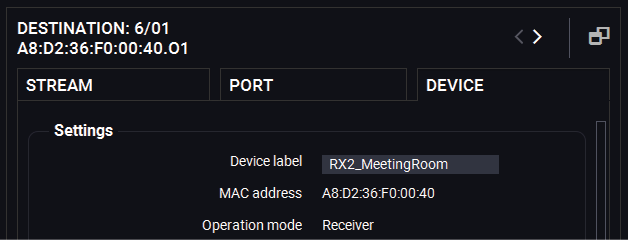
Click on the source / destination port where the device is. It does not matter you select the 01 or 02 port. Select the Device tab and find the Device label field and type a unique name which can describe the device well, for example: RX2_MeetingRoom.
Give names to the Source and Destination sides either, it will help a lot of the re-order the endpoints in the Device map.
TIPS AND TRICKS:If you are not sure which is your selected device physically, use the Identify unit function. Clicking on the button results the blinking of the front panel status LEDs for 10 seconds.
TIPS AND TRICKS:The device labels are searchable with the Search Field.
5.13.7. Add Tags to the Video Streams
More tags can be attached to the streams and devices for the effective searchability.
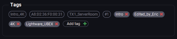
Click on the source / destination port where the stream is transmitted / received. Select the Stream tab and find the Tags section and type a custom text which can describe more streams well, for example: Edited_by_Eric, and add it to the affected streams.
INFO:The following information are automatically added to the tags: stream name, device label, logical device ID.
TIPS AND TRICKS:The tags are searchable with the Search Field.
5.13.8. Customize the Order of the Endpoints
INFO:You can find more details about the default port numbering in the Default Naming of the Devices and the Streams section.
The default order of the endpoints is generated by the MMU based on the discovery order of the units - independently of the operation mode. This order can be customized in the Device map tool.

Device map window
Click on the Device map button, the tool opens in a new window. The order of the devices can be changed easily using drag and drop method by the mouse. See more details about it in the Device Map section.
5.13.9. Set the Video Crosspoint State

Set the connections between the stream sources and the destination ports.
Move the cursor of the mouse above the desired crosspoint. You can check your selection in the Highlighted Streams section. Click on the selected crosspoint to set up the connection.
5.13.10. Set the Source MUX Settings
DEFINITION:The source multiplexer (Source MUX) makes routing several different source signals to the HDMI output ports available. The setting is available only on the output ports of the receiver and transceiver operation modes. Different types of sources are available for the different output ports.
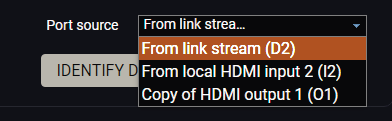
Click on the left side of the output port tile to access the MUX settings. The available options are the following:
Receiver (UBEX RX) Side
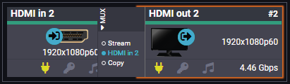
For HDMI out 1
▪Stream - The source signal is the stream received via the SFP+ links from the remote endpoint device;
▪HDMI in 1 - The source signal is the stream received via the local HDMI in 1 port.
For HDMI out 2
▪Stream - The source signal is the stream received via the SFP+ links from the remote endpoint device;
▪HDMI in 2 - The source signal is the stream received via the local HDMI in 2 port.
▪Copy - The receiver is able to copy the signal of the HDMI out 1 port. This is the COPY function.
Transceiver (UBEX TRX) Side
For HDMI out 2
▪HDMI in 2 - The source signal is the stream received via the local HDMI in 2 port.
▪Copy - The receiver is able to copy the signal of the HDMI out 1 port. This is the COPY function.
ATTENTION!If the selected source is the local input port or the copy of the HDMI out 1, the output is still selectable as a destination in the global crosspoint table. It means the crosspoint setting is not forbidden for the selected output and it is still included in the bandwidth calculation. When the sum of the two incoming streams exceeds the bandwidth limit, the signal transmission can be denied on the HDMI out 2 port even if the incoming stream of the HDMI out 1 is not used. The solution of this limitation is disabling of the unused destination port.
Appereance of the Destination Tile
When the selected source is the local input port or the copy of the HDMI out 1, the destination port tiles and the crosspoint tile appear as the following:

5.13.11. Check the Signal Bandwidth Status
Check the signal bandwidth and the bandwidth limit status indicator. When the bandwidth limit is exceeded, the source/destination port tiles and the crosspoint tile appear as the following:
▪Crosspoint (connection) tile when bandwidth limit is exceeded:

▪Source/destination port tile when bandwidth limit is exceeded:

Bandwidth Limitation
If an endpoint exceeds bandwidth limit, the MMU disable the stream of HDMI in 2 of the transmitter automatically. The stream of HDMI in 1 is transmitted continuously.
Solution
More possible solutions can be applied to avoid the bandwidth limitation:
▪Enable the scaler / FRC on the HDMI inputs of the transmitter;
▪Apply the color space conversion on the stream source(s).
▪In the case of 10 GbE link (only one SFP+ module / DAC cable is installed in the SFP+ ports) upgrade the bandwidth performance of the endpoint to 20 GbE.
5.13.12. Set the HDCP Settings

Check the HDCP settings both on the sources and destinations. For more details about HDCP technology see the HDCP Management section.
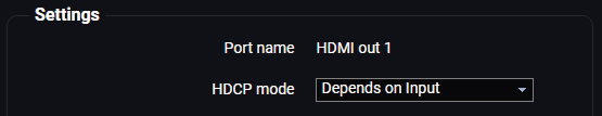
▪Click on the source port properties panels on the transmitter side and select the Port tab. Check the HDCP enable setting. Put a tick to enable HDCP capability on the port.
▪Click on the destination port properties panels on the receiver side and select the Port tab. Check the HDCP mode setting.
INFO:UBEX extenders always authenticate the highest version of HDCP-encryption and cannot force the lower version.
5.13.13. Emulate the Correct EDID
Emulate the right EDID to the HDMI input ports of the transmitter. The EDID must be set according to the desired resolution / refresh rate of the stream.
INFO:You can find detailed information about the EDID Management menu of the LDC software in the EDID Management Menu section; about the technology in general, please read the EDID Management section.
Navigate to the EDID Management in the LDC software. Set the right side of the panel to the Emulated EDIDs, and set the left panel to the Factory EDIDs. See the entire list of the pre-installed factory EDIDs in the Factory EDID List section.
Example
For HDMI in 1 (1/01)
In our example the incoming signal on the HDMI in 1 port is 4K UHD 60 Hz (3840x2160p@60Hz 4:4:4).
Select the F137 memory address on the left side and also select the E101 EDID memory slot on the Emulated side. Click on the Transfer button (the arrow in the middle) to emulate the selected EDID.
For HDMI in 2 (1/02)
In our example the HDMI in 2 port receives 1080p60 Hz signal (1920x1080p@60Hz).
Select the F49 memory track on the left side and also select the E102 EDID memory slot on the Emulated side. Click on the Transfer button (the arrow in the middle) to emulate the selected EDID.
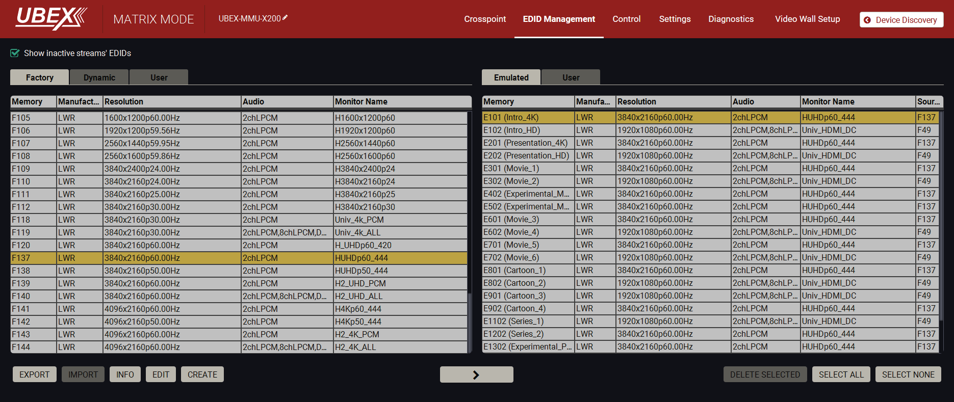
EDID Management menu in the LDC
TIPS AND TRICKS:If there is no pre-installed factory EDID in the list that can fit your system, a new EDID can be created via the EDID Creator wizard. See more details about it in the Creating an EDID - Easy EDID Creator section.
5.13.14. Set the Scalers
Set up the scalers for the best user experience. The forced resolution and refresh rate are recommended to fit the supported resolution / refresh rate of the sink device.
DIFFERENCE:The receiver is built with scaler function on both HDMI output ports and the transceiver is built with scaler function on the HDMI in 2 port from firmware version v2.1.0. These ports have FRC and CSC functions only in case of previous firmware versions.
DIFFERENCE:The transmitter is built with scaler function on both HDMI input ports from firmware version v2.4.1. HDMI in 2 port has FRC and CSC functions only in case of previous firmware versions.
Scaler - Example
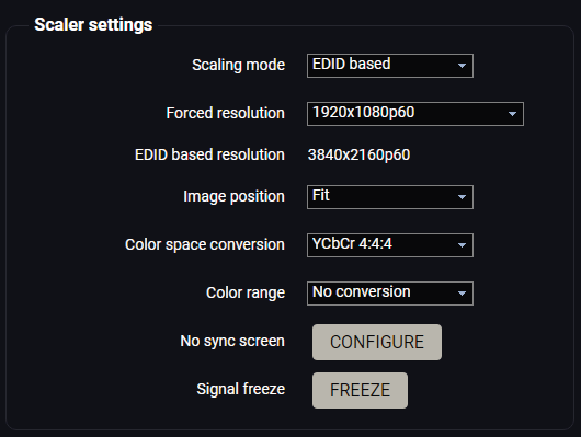
In our example the sink device is a 4K-ready monitor and we have to display a 4K60 Hz video on it. The signal is transmitted on the HDMI out 1 port of the UBEX receiver.
Click on the desired destination port and select the Port tab. Set the Scaling Mode setting to EDID based, which means the receiver reads out the EDID of the sink device and scales the image to that. In our example it is 3840x2160p60. Set the Image position to Fit, the Color space conversion to YCbCr 4:4:4.
INFO:For the video wall installation you can find a detailed tutorial in the Video Wall Setup section.
INFO:For the multiviewer installation you can find a detailed tutorial in the Multiview Designer - Tutorial section.
5.13.15. Set the Audio Crosspoint State
Set up the audio crosspoint settings. Navigate to the Crosspoint menu and select the Audio layer. Digital and analog audio source streams are also selectable in the case of UBEX-PRO20-HDMI-F110 and UBEX-PRO20-HDMI-F120 endpoint devices. All audio streams can be selected to all outputs.
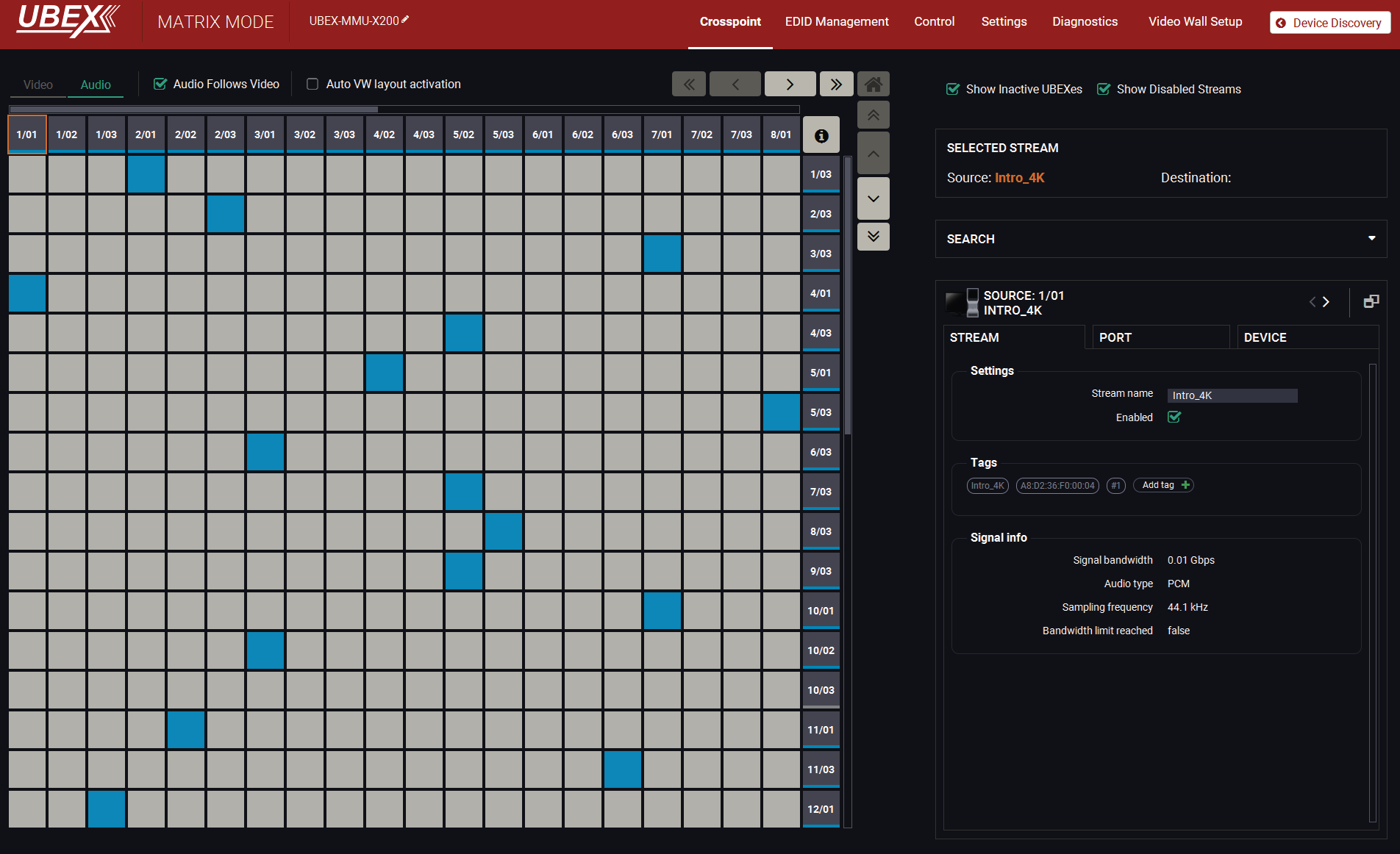
Audio crosspoint menu in the LDC
See more details about the audio crosspoint settings in LDC in the Crosspoint Menu - Audio Layer section.
DIFFERENCE:HBR audio formats are supported from LDC version v2.5.8b2, endpoint firmware version v2.0.0 and MMU firmware version v1.4.0 only. If the embedded audio signal is HBR and an HBR audio not supported error message is received during the new crosspoint setting, please update the control software to the latest one. See more information about the updating procedure in the Install and Update section.
5.13.16. Set the Parameters of the Audio Streams
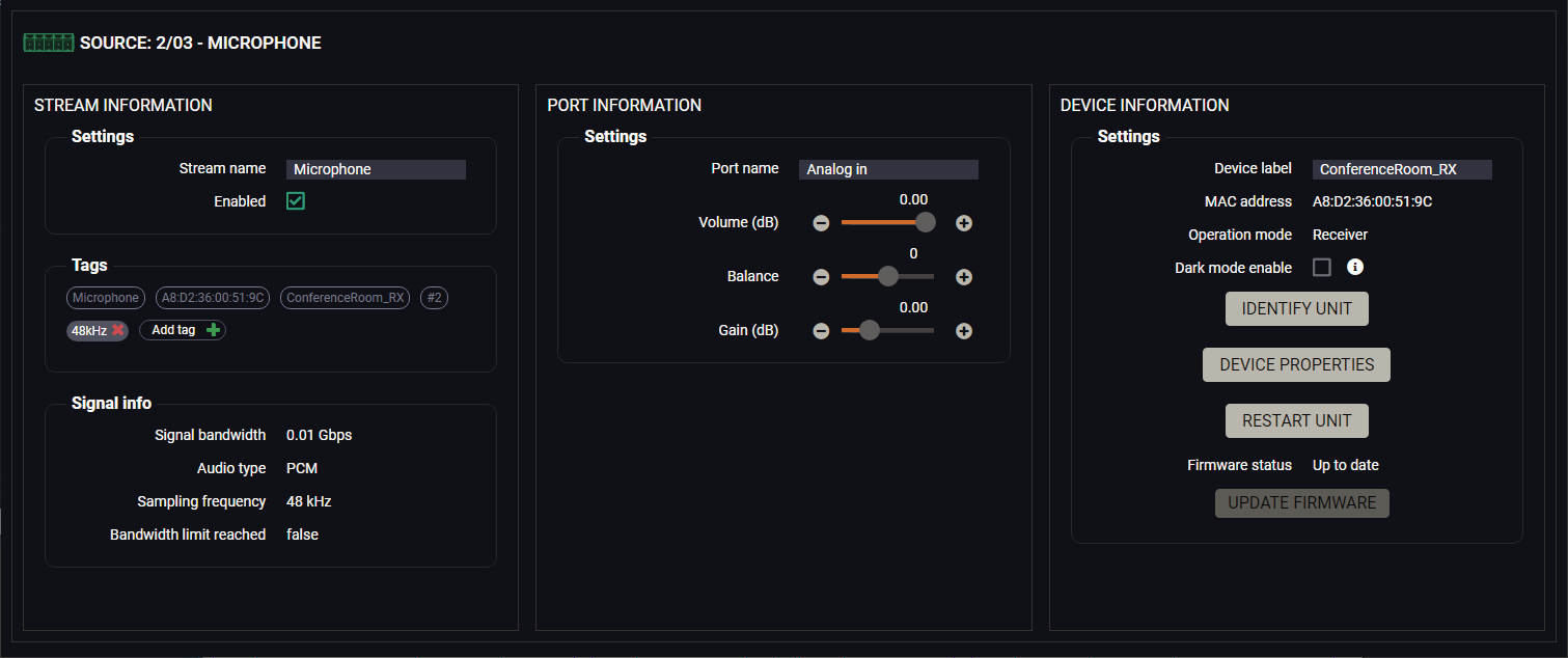
Analog audio input port properties window in the LDC
Set up and customize the analog and digital audio streams. Select the desired source or destination port and check the following settings / parameters:
▪Set a unique stream name;
▪Check the audio signal status;
▪Check the enable/disable status of the stream;
▪Set tags for the stream;
▪In case of analog signal adjust the volume, balance, gain settings.
TIPS AND TRICKS:The stream names, tags, and device labels are searchable with the Search Field.
5.13.17. Checkpoints for the Seamless Switching
UBEX series extenders provide seamless switching (clean cut) technology, which is the capability to deliver consistent performance and reliability. The advantage of the technology is that various environments with different video sources and displays will not impact signal loss. #seamless
For the best available user experience, please check the following settings being completed to fulfill the requirements of the seamless switching:
▪Emulate the correct EDID: emulate the right EDID to the HDMI input ports of the transmitter/transceiver. The EDID must be set according to the desired resolution / refresh rate of the stream. For example, emulate the F135 factory EDID track (4096x2160@24Hz 2chLPCM) for a 4096x2160@24Hz resolution.
▪Set the scaler: set the scaler on the output ports of the receiver or transceiver. The forced resolution and refresh rate are recommended to fit the supported resolution / refresh rate of the sink device. For example, if the preferred resolution of the sink device is 3840x2160@60Hz, apply the following settings in the scaler:
=Scaling mode: Forced resolution or EDID based
=Forced resolution: 3840x2160p60
=Image position: Fit
=Timing mode: Free run
▪Set the HDCP: check the HDCP settings both on the input and output ports.
=Inputs: tick the HDCP enable setting to enable.
=Outputs: if the types of the sink devices are different, set the HDCP mode to Forced HDCP 2.2 Type 1 (the sink device must support the HDCP 2.2 Type 1).
▪Set the color space: set the color space (RGB / YCbCr) and the sampling rate (4:4:4 / 4:2:2) to the same value for all sink devices in case of the color space of the signal sources being different.
▪Set the color range: if the color ranges of the signal source devices are different, this setting helps adjusting between the different types. Lightware recommends the following settings for the color range:
=If the color range of the signal source devices are the same: set to No conversion (default).
=If the color range of the signal source devices are different: set to Full range or Limited range, depending on the received source signals.
▪Set the color depth: if the color depth of the signal source and sink devices are different, this setting helps adjusting between the different types. Lightware recommends the following settings for the color depth:
=If the color depth of the source and sink devices are the same: set to Passthrough (default).
=If the color depth of the source and sink devices are different: set both side to a fixed value: 8 bpc / 10 bpc / 12 bpc.
The following chapter describes the features of the device with a few real-life examples. The topics what are described:
6.1. The Matrix Management Unit (MMU)
The Matrix Management Unit (MMU) is the brain of UBEX system in the case of Matrix mode. The MMU builds up the crosspoints; controls, manages, and supervises the endpoints connected the UBEX network.
When the endpoint devices are connected to the network and they are claimed by the MMU, the UBEX matrix became one entity which is managed by the MMU.
6.1.1. Port Diagram
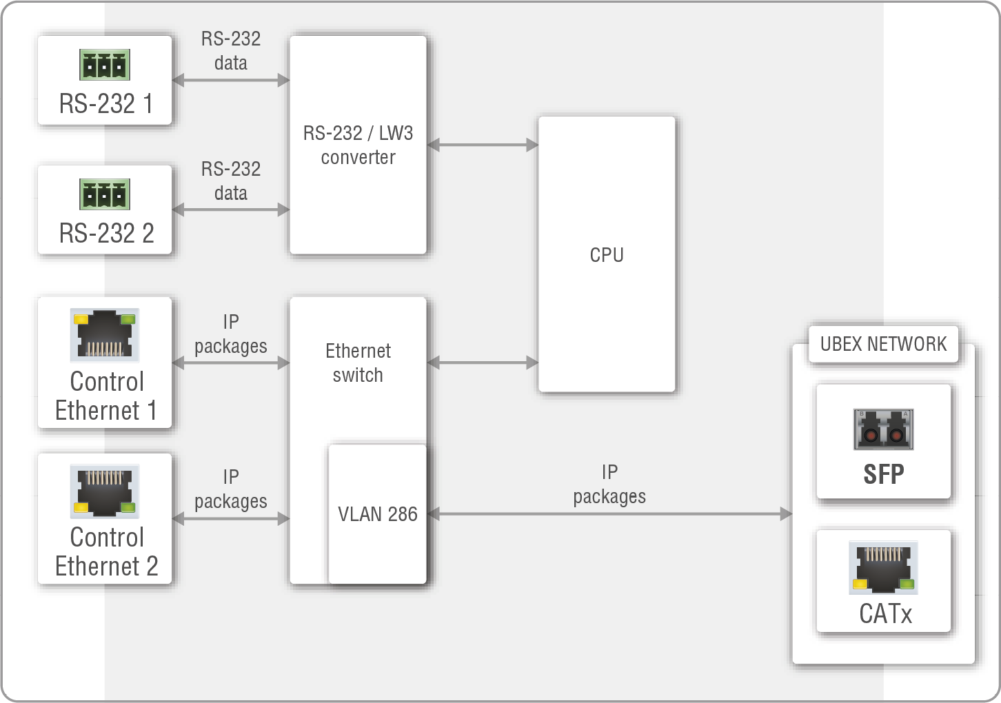
Port diagram of the Matrix Management Unit
The UBEX-MMU-X200 can receive control signals from the two serial ports (RS-232 1 and 2), and the two Ethernet ports (Control Ethernet 1 and 2).
ATTENTION!The Control Ethernet 1 port (on the front panel) supports 100 Mbps Ethernet only. The Control Ethernet 2 port (on the rear panel) supports the 1 Gbps Ethernet connection.
INFO:The MMU does not transmit HDMI signals.
The CPU forwards the RS-232 and Ethernet signals to the SFP and CATx ports and after a TCP/IP converting transmits it to UBEX endpoints.
The Functions of the Matrix Management Unit (in Matrix Mode):
▪Dynamic crosspoint handling
▪Network bandwidth utilization management
▪EDID management
▪Monitoring of the network and the endpoints
▪Backup and restore
▪Interface for third-party system controllers
▪Centralized firmware update method for the endpoint devices
What if the Connection with the MMU is lost?
If the connection with the MMU is lost, the AV signal transmission between the endpoint devices will continue without any problem. You can calculate with the following restrictions:
▪Establishing the connection to the UBEX matrix is not available;
▪Crosspoint changing is not available;
▪Dynamic EDID will not be changed in the case changing a sink device on a receiver;
▪Control features of the system are not available;
▪New endpoint devices can not be claimed.
Once the MMU returns to the system and establishes the connection with the endpoint devices, the above listed restrictions cease immediately.
Description
The Endpoint License for Matrix Management Unit means the number of endpoint devices which are able to be claimed by the MMU is limited. The default value of the limition is 16. The number of claimable UBEX endpoint devices can be expanded by the user. The following table shows the available endpoint licenses:
|
Name |
Description |
|---|---|
|
UBEX-MMU-X200-16 |
UBEX-MMU-X200 limited to 16 endpoints. This is default value of the MMU, no license is applied on the device. |
|
UBEX-MMU-X200-50 |
UBEX-MMU-X200 limited to 50 endpoints. |
|
UBEX-MMU-X200-100 |
UBEX-MMU-X200 limited to 100 endpoints. |
|
UBEX-MMU-X200-150 |
UBEX-MMU-X200 limited to 150 endpoints. |
|
UBEX-MMU-X200 |
UBEX-MMU-X200 has no endpoint limitation by software. |
|
Upgrading a level |
UBEX MMU-X200 upgrading to the next level. |
|
Upgrading to unlimited level |
UBEX MMU-X200 upgrading to unlimited from the last limitation level. |
INFO:The MMU can be upgraded by purchasing one of the listed license. For more details, please contact sales@lightware.com. #license
Features and Properties of the Endpoint Licenses
▪The MMU can be upgraded to higher level anytime.
▪One license can be applied for one MMU.
▪The licenses do not expire (the time of the usage is unlimited for all level of licenses).
▪The endpoint devices are able to be claimed as much as the limition of the recent license is. For example, if the matrix installed with 18 endpoints, but the MMU has a Level 1 license with 16-endpoint limitation, 2 of the 18 endpoint devices will not be claimed.
▪The MMU reboots after a new license is applied or a license is removed.
▪If the license is removed, but more than 16 endpoint devices have already been claimed by the MMU, the already claimed endpoint devices remain a part of the UBEX matrix. The only restriction is that claiming new devices is not allowed until a valid license is applied.
The following sections are about how to control the endpoint devices and the Matrix Management Unit by a computer or any third-party controller.
INFO:It does not matter which device (the MMU directly or any endpoints) you want to use establishing connection with the UBEX matrix, you will reach the MMU finally.
The following interfaces can be used to control the matrix:
|
Interface |
MMU |
Endpoints |
|
|
|
|
|

|
|
|
|
ATTENTION!The RS-232 port of the F110 and F120 endpoint models can be used for controlling third-party devices only.
INFO:The USB control interface for the MMU will be added by a future firmware update.
Description
The endpoint devices and the Matrix Management Unit can be controlled over Ethernet interface. The ports are standard RJ45 connectors in the case of endpoint and the MMU as well.
ATTENTION!When you connect to an endpoint, you reach the MMU from the control point of view. The control commands and settings are done in the MMU finally.
The matrix can be configured with the following tools:
▪Lightware Device Controller (LDC) software (details: Software Control - Lightware Device Controller);
▪LW3 protocol commands (details: Programmers Reference).
Bandwidth Differences between the Ethernet Connectors
The rear side Ethernet connector has 1 Gbps bandwidth capability, the front side Ethernet connector is limited to 100 Mbps.
ATTENTION!Pay attention to the configuration of the port of the network switch where the Ethernet control port of the MMU is connected to.
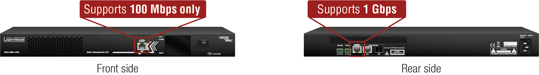
Matrix Control over Ethernet - Example
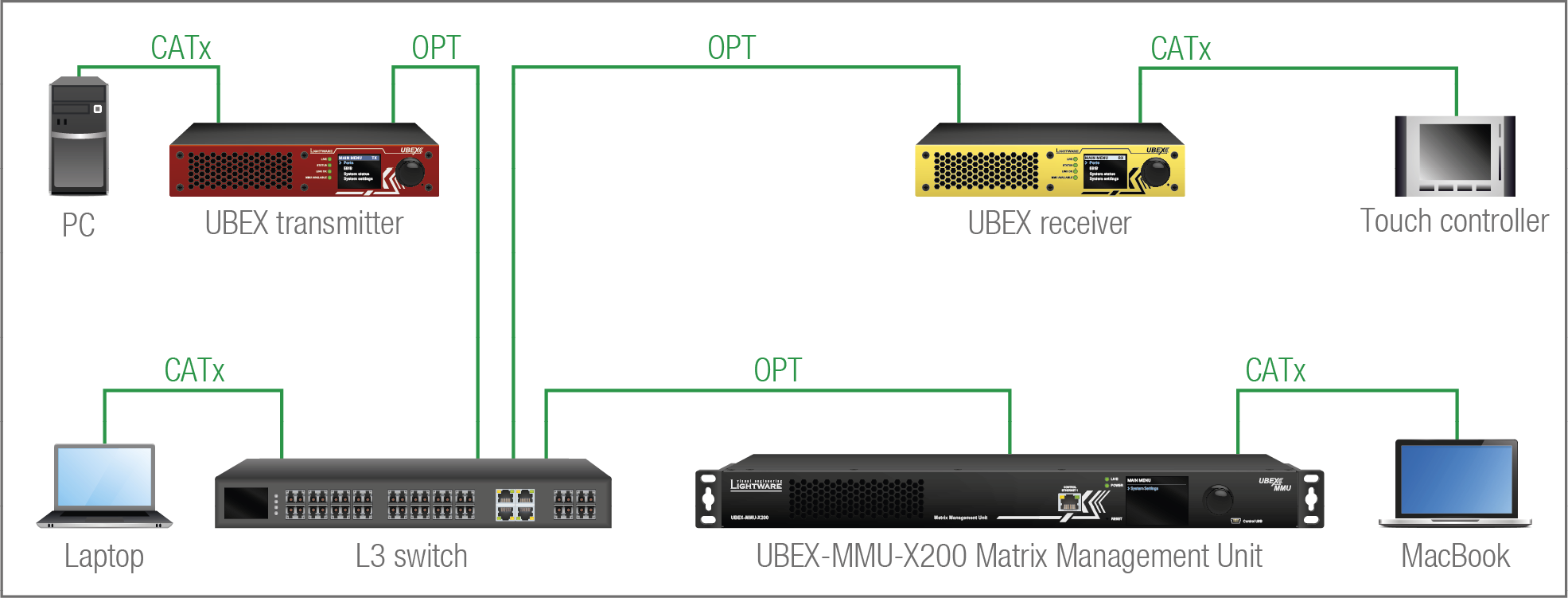
The Concept
The matrix has one transmitter and one receiver connected to an L3 switch and supervised by the MMU. There are four control devices connected to the network: a PC to the transmitter, a touch controller to the receiver, a laptop to the switch, and a MacBook to the MMU. It does not matter which device you want to use for controlling, all of them reach the MMU and you can configure the matrix.
This section is about the serial interface of the MMU.
ATTENTION!The RS-232 port of the endpoint devices cannot be used for controlling the UBEX matrix.
Description
The Matrix Management Unit contains 2 pieces of 3-pole Phoenix connectors for serial communication. The interface can be used for controlling the MMU or the matrix.
The matrix can be configured with the following tools:
▪Lightware Device Controller (LDC) software (details: Software Control - Lightware Device Controller);
▪LW3 protocol commands (details: Programmers Reference).
Matrix Control over RS-232 - Example
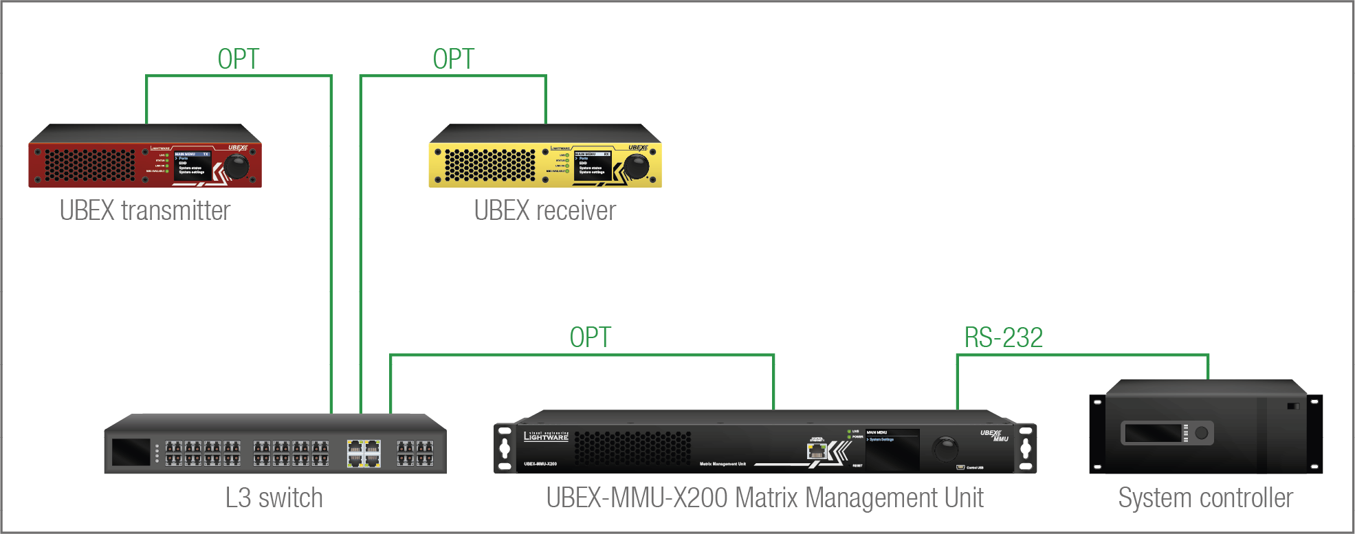
The Concept
The endpoint devices are connected to the UBEX matrix over the network switch via the optical ports. The MMU is controlled by the system controller over the serial interface by LW3 protocol commands. All AV related actions are available with LW3 protocol, e.g. crosspoint switching, EDID management, scaling, etc.
Port Diagram
The port diagram is valid for the following UBEX endpoint models:
▪UBEX-PRO20-HDMI-F100; -F110; -F111; -F120; -F121; -F130
▪UBEX-PRO20-HDMI-R100 series
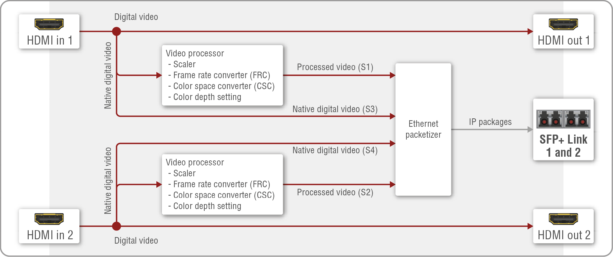
Video port diagram of the F-series and R-series transmitter
HDMI Input Modes
The transmitter can receive HDMI video streams from two HDMI 2.0 input ports. The signals can be up to 4K@60 Hz 4:4:4 in the case of both inputs.
The video streams of the HDMI inputs can be processed in the video processors. The processor of the HDMI in 1 and 2 have video scaler, frame rate converter (FRC), color space converter (CSC) and color depth setting functions.
DIFFERENCE:The transmitter is built with scaler function on both HDMI input ports from firmware version v2.4.1. The HDMI in 2 port has FRC and CSC functions only in case of previous firmware versions.
The scaler, frame rate converter, color space converter and color depth settings are available in the LDC software (see the details in the Video Source Port Properties Window or in the Stream Properties Panels section).
DIFFERENCE:The scaler supports up to 10 bit/channel color space conversion from firmware package v3.3.0.
The native AV streams (e.g. with 12 bit/channel (deep color) support) can also be transmitted, altogether four streams are switchable on the remote UBEX extender. Please check the 20G bandwidth limitation before the transmission. Find more help for the calculation in the Bandwidth Requirements of the Resolutions section.
HDMI Output Modes
The HDMI output ports of the transmitter are HDMI loop-back ports and can be used as local HDMI outputs. The HDMI output 1 transmits the signal of the HDMI input 1 port, the HDMI output 2 transmits the signal of the HDMI input 2 port.
Fiber Optical Interface
After the Ethernet packetizing, the two video streams are transmitted to the remote endpoint device via the fiber optical ports.
Summary Tables
|
HDMI INPUTS |
||||
|
HDMI input 1 |
HDMI input 2 |
|||
|
Processed stream |
Native stream |
Processed stream |
Native stream |
|
|
Accepted signal |
up to 4K@60 4:4:4 |
up to 4K@60 4:4:4 |
||
|
Scaler |
|
- |
|
- |
|
Frame rate converter (FRC) |
|
- |
|
- |
|
Color space converter (CSC) |
|
- |
|
- |
|
Color depth setting |
|
- |
|
- |
|
HDMI OUTPUTS |
||
|
HDMI output 1 |
HDMI output 2 |
|
|
Output signal |
up to 4K@60 4:4:4 |
up to 4K@60 4:4:4 |
|
Signal source |
HDMI input 1 |
HDMI input 2 |
2x 4K60 Transmission
The UBEX transmitter is built with 2 pcs of HDMI 2.0 input ports that are capable of receiving 2x 4K60 4:4:4 video streams from the source devices. The two streams together require more than 20 Gbps on the SFP+ links, so this is the bottleneck of the transmission on the fiber optical link. UBEX endpoints offer several settings and AV signal adjustments, that make it possible to transmit 2x 4K60 signal on 20G:
▪Color space conversion (CSC): The built-in color space converter (CSC) helps keeping the resolution of the stream at the expense of the picture quality. If 4:4:4 color sampling generates one unit bandwidth, then in case of 4:2:2 the bandwidth will be 66% of it; in case of 4:2:0, it is halved.
▪Color depth setting: The color depth of the stream can be set on both HDMI input ports. HDMI 2.0 signal in YCbCr color space has 12 bit/channel color depth (over 68 billion possible colors) by default, but it can be converted to 8 bit/channel (16 million possible colors) or 10 bit/channel (1 billion possible colors).
See more details about the bandwidth calculation of the UBEX extenders and more useful tips & tricks in the Bandwidth Requirements of the Resolutions section.
Port Diagram
The port diagram is valid for the following UBEX endpoint models:
▪UBEX-PRO20-HDMI-F100; -F110; -F111; -F120; -F121; -F130
▪UBEX-PRO20-HDMI-R100 series
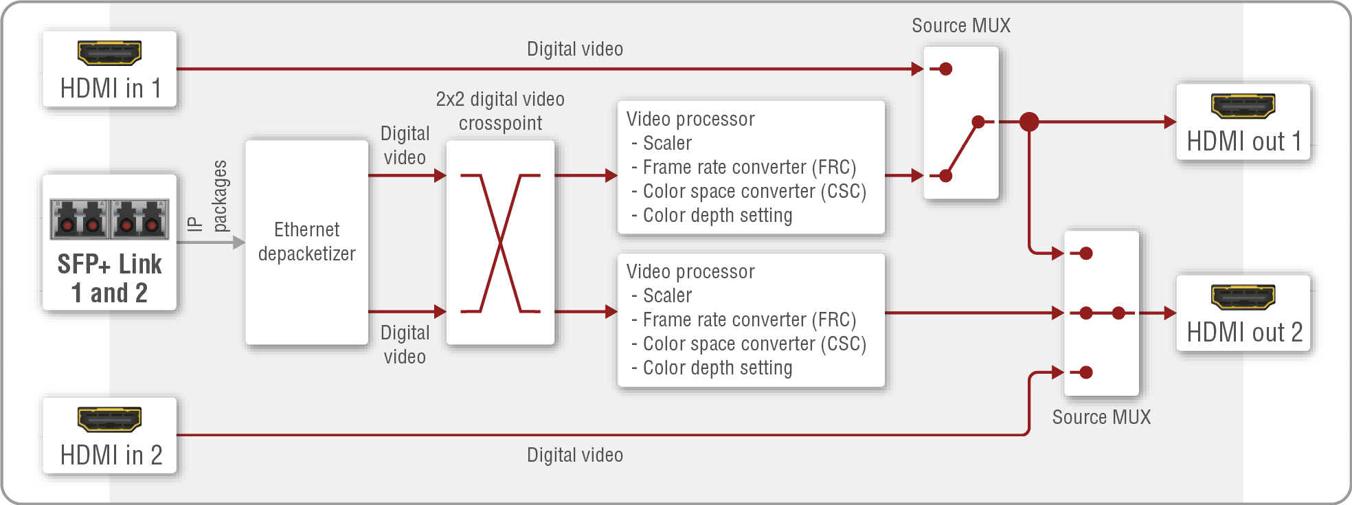
Video port diagram of the F-series and R-series receiver
Fiber Optical Interface
The receiver can receive two HDMI video streams via the fiber optical input ports.
HDMI Output Modes
The receiver can transmit HDMI video streams on two HDMI 2.0 output ports. The signal can be up to 4K@60 Hz 4:4:4 in the case of both outputs. The streams received from the remote endpoint device can be routed to any HDMI outputs of receiver, e.g. the stream from the TX - HDMI in 1 can be switched to the RX - HDMI out 1 or 2, or both ones either.
The streams can be processed in the video processors. The processor of the HDMI out 1 and 2 have video scaler, frame rate converter (FRC), color space converter (CSC) and color depth setting functions.
DIFFERENCE:The receiver is built with scaler function on both HDMI output ports from firmware version v2.1.0. The HDMI out 2 port has FRC and CSC functions only in case of previous firmware versions.
The scaler, frame rate converter, and color space converter settings are available in the LDC software (see the details in the Video Destination Port Properties Window or in the HDMI Output Ports section).
Source Multiplexer (MUX)
The source multiplexer (Source MUX) makes routing several different source signals to the HDMI output ports available. The type of sources is different for the two outputs.
HDMI out 1
▪Able to accept signal up to 4K@60 4:4:4 resolution via the SFP+ links from the remote endpoint device;
▪Able to accept signal up to 4K@60 4:4:4 resolution via the local HDMI in 1 port.
HDMI out 2
▪Able to accept signal up to 4K@60 4:4:4 resolution via the SFP+ links from the remote endpoint device;
▪Able to accept signal up to 4K@60 4:4:4 resolution via the local HDMI in 2 port;
▪Able to copy the signal of the HDMI out 1 port up to 4K@60 4:4:4 resolution. This is the COPY function.
ATTENTION!If the selected source is the local input port or the copy of the HDMI out 1, the output is still selectable as a destination in the global crosspoint table. It means the crosspoint setting is not forbidden for the selected output and it is still included in the bandwidth calculation. When the sum of the two incoming streams exceeds the bandwidth limit, the signal transmission can be denied on the HDMI out 2 port even if the incoming stream of the HDMI out 1 is not used. When the sum of all incoming streams exceeds the bandwidth limit, the signal transmission can be denied on the HDMI out 2 port even if some of the incoming streams of the HDMI out 1 are not used. The solution of this limitation is to disable the unused destination port.
HDMI Input Modes
The HDMI input ports of the receiver operate as local HDMI inputs. The stream cannot be affected by any video processing.
Summary Tables
|
HDMI INPUTS |
||
|
HDMI input 1 |
HDMI input 2 |
|
|
Accepted signal |
up to 4K@60 4:4:4 |
up to 4K@60 4:4:4 |
|
Signal sink |
HDMI output 1 |
HDMI output 2 |
|
HDMI OUTPUTS |
|||||
|
HDMI output 1 |
HDMI output 2 |
||||
|
Output signal |
up to 4K@60 4:4:4 |
up to 4K@60 4:4:4 |
|||
|
Signal source |
Source MUX |
Source MUX |
|||
|
Selected input port of the remote device |
Local HDMI input 1 |
Selected input port of the remote device |
Local HDMI input 2 |
Copy of the HDMI output 1 |
|
|
Scaler |
|
- |
|
- |
- |
|
Frame rate converter (FRC) |
|
- |
|
- |
- |
|
Color space converter (CSC) |
|
- |
|
- |
- |
|
Color depth setting |
|
- |
|
- |
- |
Port Diagram
The port diagram is valid for the following UBEX endpoint models:
▪UBEX-PRO20-HDMI-F100; -F110; -F111; -F120; -F121; -F130
▪UBEX-PRO20-HDMI-R100 series
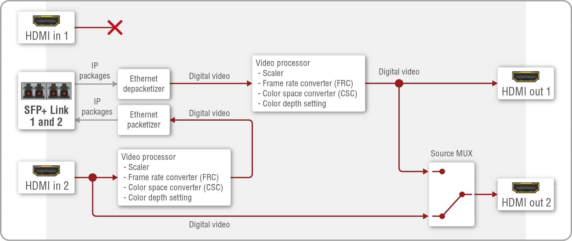
Video port diagram of the F-series and R-series transceiver
Fiber Optical Interface
The transceiver is able to send and receive HDMI video streams together at the same time over the fiber optical links.
HDMI Input Modes
The transceiver can receive one HDMI video stream from the HDMI in 2 input port. The signal can be up to 4K@60 Hz 4:4:4. The video stream can be processed in the video processor. The processor of the HDMI in 2 has video scaler, frame rate converter (FRC), color space converter (CSC) and color depth setting functions. The video processor settings are available in the LDC software (see the details in the Video Source Port Properties Window or in the Source Stream Panel section).
ATTENTION!The HDMI in 1 input port cannot accept video signal.
HDMI Output Modes
The transceiver can transmit HDMI video streams on two HDMI 2.0 output ports. The signal can be up to 4K@60 Hz 4:4:4 in the case of both outputs.
The HDMI out 1 transmits the HDMI signal coming from the remote UBEX endpoint. The video stream can be processed in the video processor (it contains scaler, frame rate converter (FRC), color space converter (CSC) and color depth setting functions). The video processor settings are available in the LDC software (see the details in the Video Destination Port Properties Window or in the HDMI Out 1 Panel section).
In default state, the HDMI out 2 transmits the HDMI signal coming from the HDMI in 1 input port so it operates as a local output port. The stream cannot be affected by any video processing.
Source Multiplexer (MUX)
The source multiplexer (Source MUX) makes routing several different source signals to the HDMI output 2 port available.
HDMI out 2
▪Able to accept signal up to 4K@60 4:4:4 resolution via the local HDMI in 2 port;
▪Able to copy the signal of the HDMI out 1 port up to 4K@60 4:4:4 resolution. This is the COPY function.
ATTENTION!If the selected source is the local input port or the copy of the HDMI out 1, the output is still selectable as a destination in the global crosspoint table. It means the crosspoint setting is not forbidden for the selected output and it is still included in the bandwidth calculation. When the sum of the two incoming streams exceeds the bandwidth limit, the signal transmission can be denied on the HDMI out 2 port even if the incoming stream of the HDMI out 1 is not used. The solution of this limitation is disabling of the unused destination port.
Summary Tables
|
HDMI INPUTS |
||
|
HDMI input 1 |
HDMI input 2 |
|
|
Accepted signal |
|
up to 4K@60 4:4:4 |
|
Scaler |
- |
|
|
Frame rate converter (FRC) |
- |
|
|
Color space converter (CSC) |
- |
|
|
Color depth setting |
- |
|

|
HDMI OUTPUTS |
|||
|
HDMI output 1 |
HDMI output 2 |
||
|
Output signal |
up to 4K@60 4:4:4 |
up to 4K@60 4:4:4 |
|
|
Signal source |
Input port of the remote device |
Source MUX |
|
|
HDMI input 2 |
Copy of the HDMI output 1 |
||
|
Scaler |
|
- |
- |
|
Frame rate converter (FRC) |
|
- |
- |
|
Color space converter (CSC) |
|
- |
- |
|
Color depth setting |
|
- |
- |
2x 4K60 Transmission
The UBEX transceiver is built with a HDMI 2.0 input port and a HDMI 2.0 output port as well that are capable of transmitting 2x 4K60 4:4:4 video streams. The two streams together require more than 20 Gbps on the SFP+ links, so this is the bottleneck of the transmission on the fiber optical link. UBEX endpoints offer several settings and AV signal adjustments, that make it possible to transmit 2x 4K60 signal on 20G:
▪Color space conversion (CSC): The built-in color space converter (CSC) helps keeping the resolution of the stream at the expense of the picture quality. If 4:4:4 color sampling generates one unit bandwidth, then in case of 4:2:2 the bandwidth will be 66% of it; in case of 4:2:0, it is halved.
▪Color depth setting: The color depth of the stream can be set on both HDMI input ports. HDMI 2.0 signal in YCbCr color space has 12 bit/channel color depth (over 68 billion possible colors) by default, but it can be converted to 8 bit/channel (16 million possible colors) or 10 bit/channel (1 billion possible colors).
See more details about the bandwidth calculation of the UBEX extenders and more useful tips & tricks in the Bandwidth Requirements of the Resolutions section.
Two video streams can be transmitted at the same time from an endpoint device up to 20 Gbps bandwidth. When the bandwidth limit is exceeded, the priority of the streams is the following:
Transmitter Side
The stream of the HDMI in 1 has the higher priority and the stream of the HDMI in 2 will not be transmitted until the bandwidth limit problem is solved (the parameters of the video are still received by the receiver). In that case the stream tile of the disabled stream becomes amber in the LDC software.
|
Transmitter side |
HDMI in 1 |
HDMI in 2 |
||||
|
Status |
Stream tile (LDC) |
Port tile (LDC) |
Status |
Stream tile (LDC) |
Port tile (LDC) |
|
|
Enabled |

|

|
Disabled |

|

|
|
Receiver Side
The switched stream of the HDMI out 1 has the higher priority and the stream of the HDMI out 2 is going to be disabled (the parameters of the video are still received). In that case the stream tile of the disabled stream becomes amber in the LDC software.
|
Receiver side |
HDMI out 1 |
HDMI out 2 |
||||
|
Status |
Stream tile (LDC) |
Port tile (LDC) |
Status |
Stream tile (LDC) |
Port tile (LDC) |
|
|
Enabled |

|

|
Disabled |

|

|
|
Transceiver Side
Thanks to the 20G full-duplex SFP+ interface, the transceiver has no bandwidth limitation on the input and output sides either. The device is able to receive and transmit 2x 4K60 Hz 4:4:4 24bit streams on the HDMI input and output ports either.
|
Transceiver side |
HDMI in 2 |
HDMI out 1 |
||||
|
Status |
Stream tile (LDC) |
Port tile (LDC) |
Status |
Stream tile (LDC) |
Port tile (LDC) |
|
|
Enabled |
|

|
Enabled |
|
|
|
INFO:You can find the bandwidth requirements of each resolution in the Bandwidth Requirements of the Resolutions section.
6.3.5. The Difference between the Image Positions of the Scaler
The following section helps to understand how the image position settings of the scaler works. Three different image positions are available: stretch, fit and center.
DIFFERENCE:The receiver is built with scaler function on both HDMI output ports and the transceiver is built with scaler function on the HDMI in 2 port from firmware version v2.1.0. The HDMI out 2 port has FRC and CSC functions only in case of previous firmware versions.
DIFFERENCE:The transmitter is built with scaler function on both HDMI input ports from firmware version v2.4.1. The HDMI in 2 port has FRC and CSC functions only in case of previous firmware versions.
The aspect ratio of the original stream and the sink device are different in the following examples.
Stretch
The aspect ratio of the stream is distorted because it is adjusted to the aspect ratio of the sink.
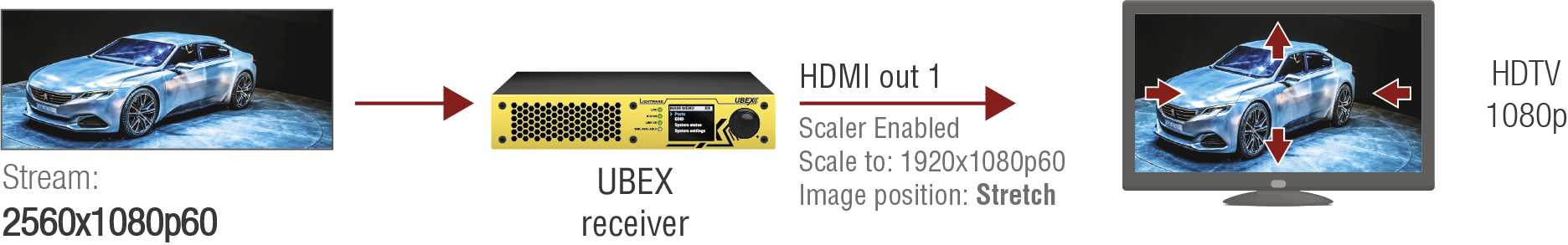
Fit
The picture is adjusted to the resolution of the sink and the aspect ratio of the stream is kept, thus the whole picture will be displayed without cropping. The scaler fills the extra image part with black pixels.
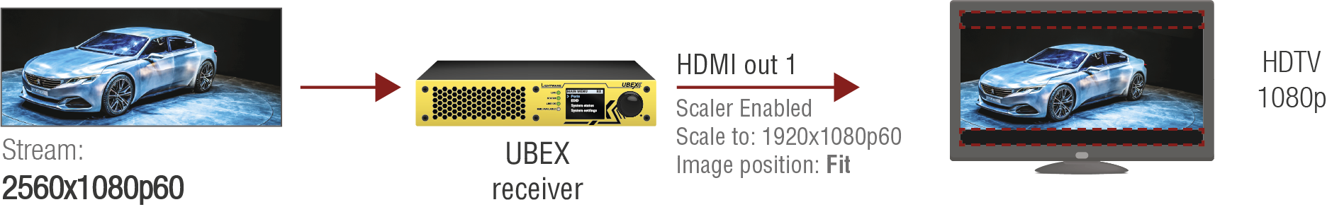
Center
The scaler crops the center part of the stream with the resolution of the sink.
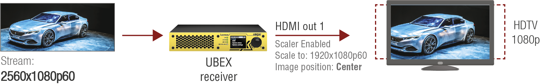
Technical Background
UBEX receivers and transceivers provide two different timing modes on the HDMI outputs:
▪Free run: the receiver generates nominal clock frequency, which is not bonded to the source. It means TBC (time base correction) is applied in the stream, which may cause frame repetition/drop between minimum 1 and maximum 2 frames value. The seamless stream switching is available in this mode only.
▪Source locked: time stamps are transmitted with the stream from the source, and the receiver can generate accurate clock frequency; in this way the latency within one frame (up to 16 lines) can be guaranteed. This mode is ideal for the video walls where the extra low latency is the most important requirement.
ATTENTION!Seamless switching is available only if the timing mode is set to free run.
The setting is available in the LDC software (see the details in the Port Information section) and by LW3 protocol commands (see the details in the Timing Mode Setting section).
Application of Timing Mode Settings - Example
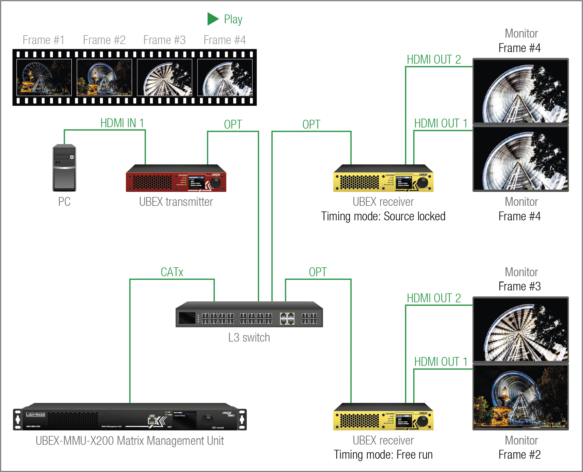
The Concept
The stream of the PC is selected on all four outputs of the UBEX receivers. The playing of the stream is at the Frame #4 at this moment.
The HDMI output ports of the upper UBEX receiver are set to source locked so the video stream is generated in the receiver, which does not engage any delay compared to the original stream.
The HDMI output ports of the lower UBEX receiver are set to free run. The differences between the actual content of the connected monitors might be noticeable.
6.3.7. HDMI Signal Transmission - Example
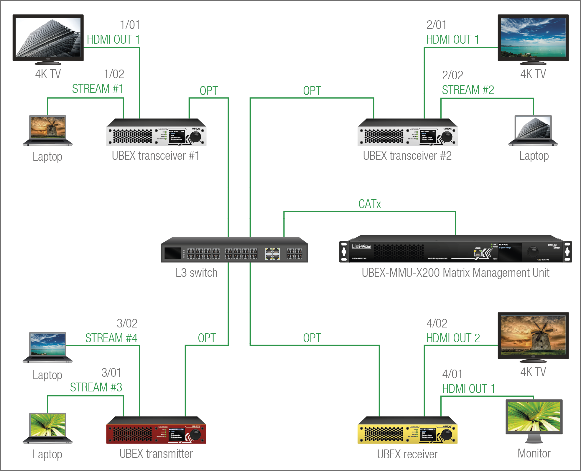
The Concept
This example shows a 4x4 UBEX matrix with an L3 network switch and the MMU in its center. The matrix contains 4 inputs (Stream #1..4) and 4 outputs (2x 1 HDMI output per transceiver and 2 pcs HDMI outputs of the receiver). The MMU builds up the crosspoints and controls the AV system.
Crosspoint Settings

The best overview of the crosspoint settings is available in the Lightware Device Controller software. The following description based on the software.
INFO:See the comprehensive description of the LDC software in the Software Control - Lightware Device Controller chapter.
The upper tiles mean the inputs (Stream #1..4 - processed streams, Stream #5-6 - native streams of the transmitter), the tiles on the right side mean the outputs (HDMI out 1 and 2 of the receivers). The naming is the following:
▪Sources: 1/02, where the 1 is the UBEX transceiver #1 (the first endpoint which is joined to the network and added by the MMU), the 02 is the Stream #1 on the HDMI in 2 port.
▪Destinations: 4/02, where the 4 is the UBEX receiver (the fourth endpoint which is joined to the network and added by the MMU), the 02 is the HDMI out 2 port of the receiver.

|
The tile means a denied connection (only for transceivers). The explanation is the input port of the transceiver cannot be selected to the output port of the same transceiver. |
Port Numbering
The following table shows which port ID belongs to the HDMI ports.
|
UBEX Endpoint |
HDMI Port |
Stream |
Port ID |
|
|
UBEX transceiver #1 |
HDMI IN 2 |
Stream #1 |

|
1/02 |
|
HDMI OUT 1 |
- |
1/01 |
||
|
UBEX transceiver #2 |
HDMI IN 2 |
Stream #2 |

|
2/02 |
|
HDMI OUT 1 |
- |
2/01 |
||
|
UBEX transmitter |
HDMI IN 1 |
Processed - Stream #3 |

|
3/01 |
|
Native - Stream #5 |
|
3/03 |
||
|
HDMI IN 2 |
Processed - Stream #4 |

|
3/02 |
|
|
Native - Stream #6 |
|
3/04 |
||
|
UBEX receiver |
HDMI OUT 1 |
- |
4/01 |
|
|
HDMI OUT 2 |
- |
4/02 |
||
Crosspoint Possibilities
The following table shows the available crosspoint possibilities:
|
Crosspoint possibilities of the video streams for the UBEX matrix |
Destinations |
|||||||
|
TRX #1 |
TRX #2 |
RX |
||||||
|
1/01 |
2/01 |
4/01 |
4/02 |
|||||
|
4K TV |
4K TV |
4K TV |
Monitor |
|||||
|
Sources |
TRX #1 |
Laptop |
1/02 |
Stream #1 |
- |
|
|
|
|
TRX #2 |
Laptop |
2/02 |
Stream #2 |
|
- |
|
|
|
|
TX |
Laptop |
3/01 |
Stream #3 |
|
|
|
|
|
|
Laptop |
3/02 |
Stream #4 |
|
|
|
|
||
Summary: The video streams of the transmitters can be selected to all sink devices. The video stream of a transceiver is not selectable to the output of the same transceiver.
Stream Identifying Tools
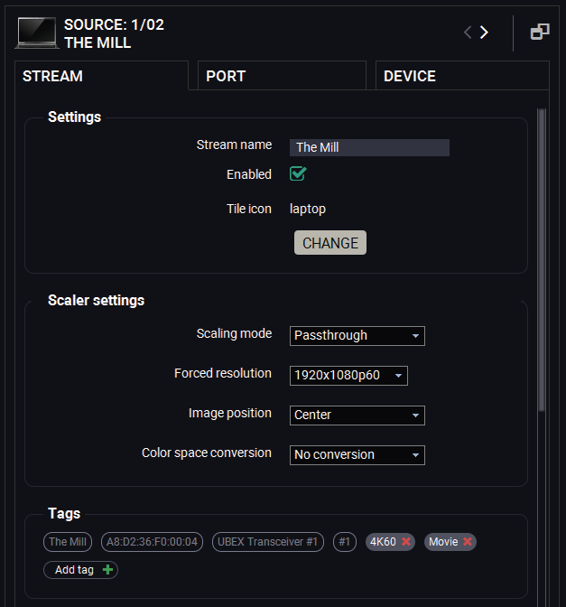
User can add a unique name and additionally tags can be attached to the stream. In this way the streams become searchable easily.
The following settings help the user to handle the streams in a bigger matrix:
▪Stream name: a unique name given by the user, like "The Mill";
▪Tags: more tags can be attached to the stream to help identifying it. You can search for words and LDC shows the hits.
=The first three outlined tags are fixed: the stream name, MAC address, and the logical device ID; these ones cannot be removed from the tags.
=The following tags are freely configurable by the user. The following characters are allowed when naming: Letters (A-Z) and (a-z), numbers (0-9), and any special characters, except semicolon ( ; ).
Stream Search

Use the Search field to find any stream on the network. You can search in the Sources, in the Destinations, or Both. Start typing in the field the LDC lists the hits and narrows it during the typing. See the details in the Search Field section.
Scaling Options
If a 4K60 stream is switched to a HD monitor, it cannot display the high-resolution video. The solution is to scale the stream to lower resolution which can be supported by the sink device. Two options are available:
▪The stream is re-scaled on the source (TX) side - in this case the stream is transmitted with HD resolution to the receiver, additionally you can optimize the network bandwidth usage as well.
▪The stream is re-scaled on the destination (RX or TRX) side - the original 4K60 signal is transmitted to the receiver and it is re-scaled on the output port.
Device Map

The default order of the endpoint devices can be reconfigured easily using drag & drop method with the Device map tool.
The intelligent search tool in the device map makes possible to find the desired endpoint device and handle a bigger matrix effectively.
The current operation mode (transmitter, receiver, or transceiver) can also be changed in the Device map.
See the details about the tool in the Device Map section.
6.4.1. Description
The UBEX matrix has built-in video wall feature which can be configured countless ways. The main properties of the video wall: #videowall #vw
▪Handles up to 8x4 (column x row) display devices;
▪More different layouts for the same video wall;
▪Zones within the video wall;
▪Easily applicable display bezel and gap correction;
▪Works in receiver and transceiver operation modes as well;
▪Interactive GUI in the LDC software for the easier handling;
▪Editable with LW3 protocol commands;
DIFFERENCE:The receiver is built with scaler function on both HDMI output ports from firmware version v2.1.0. Both HDMI out 1 and 2 ports of the receiver can participate in the video wall.
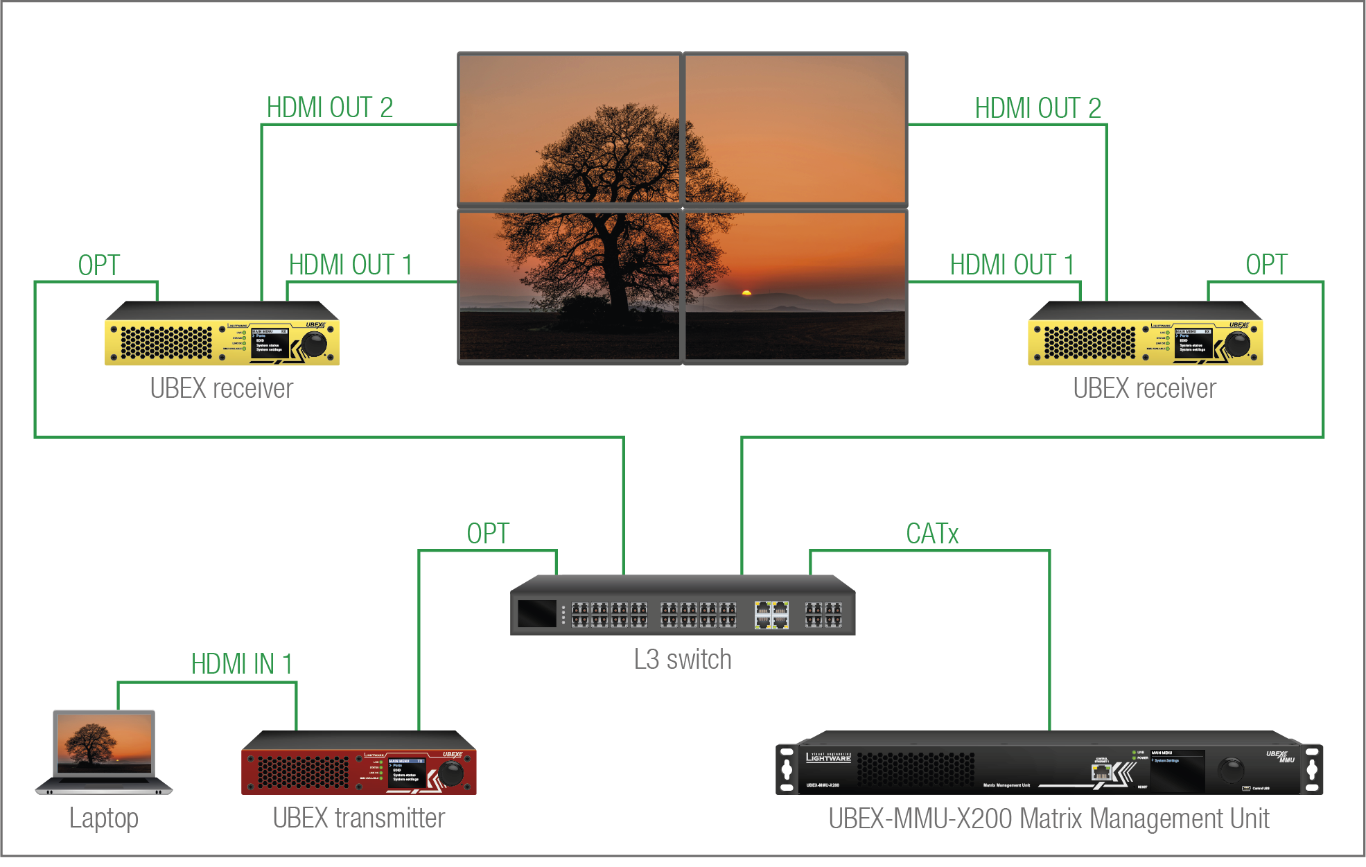
Installation example for the video wall
6.4.2. Layouts and Zones
More different layouts can be defined within a video wall installation. The layouts contain one or more zones where different sized video walls can be displayed. The different zones can display different source streams.
You can find a detailed tutorial how to create video walls, layouts, and define zones in the Video Wall Setup section.
The following figures show some examples for the usage of the layouts and the zones. The size of the video wall is always 4x4 in our example.
The Default Layout
When a video wall is created, the default layout contains one zone only (Zone 0) which includes all displays in the video wall showing one stream.

Layout with Four Zones
The next layout example contains four zones which displays four different source streams. Each zones have four display devices.
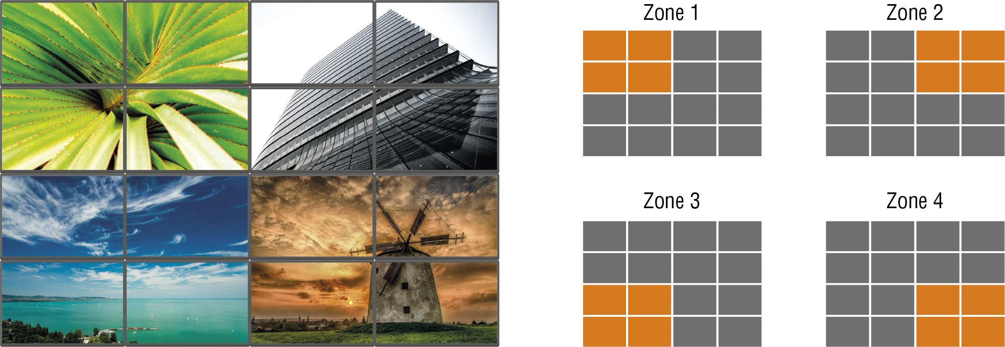
Layout with Six Zones
The next layout example contains six zones which displays six different source streams. It has a 3x3, a 3x1, and four standalone zones with one display device per zone.

6.4.3. Identifying of the Display/Zone
The UBEX video wall system has a feature to help identifying a display device or a zone physically. When you need to see quickly which display or zone you want to configure actually, this feature generates 10 test colors on the display device(s) for 10 seconds.
Example for Identifying a Display
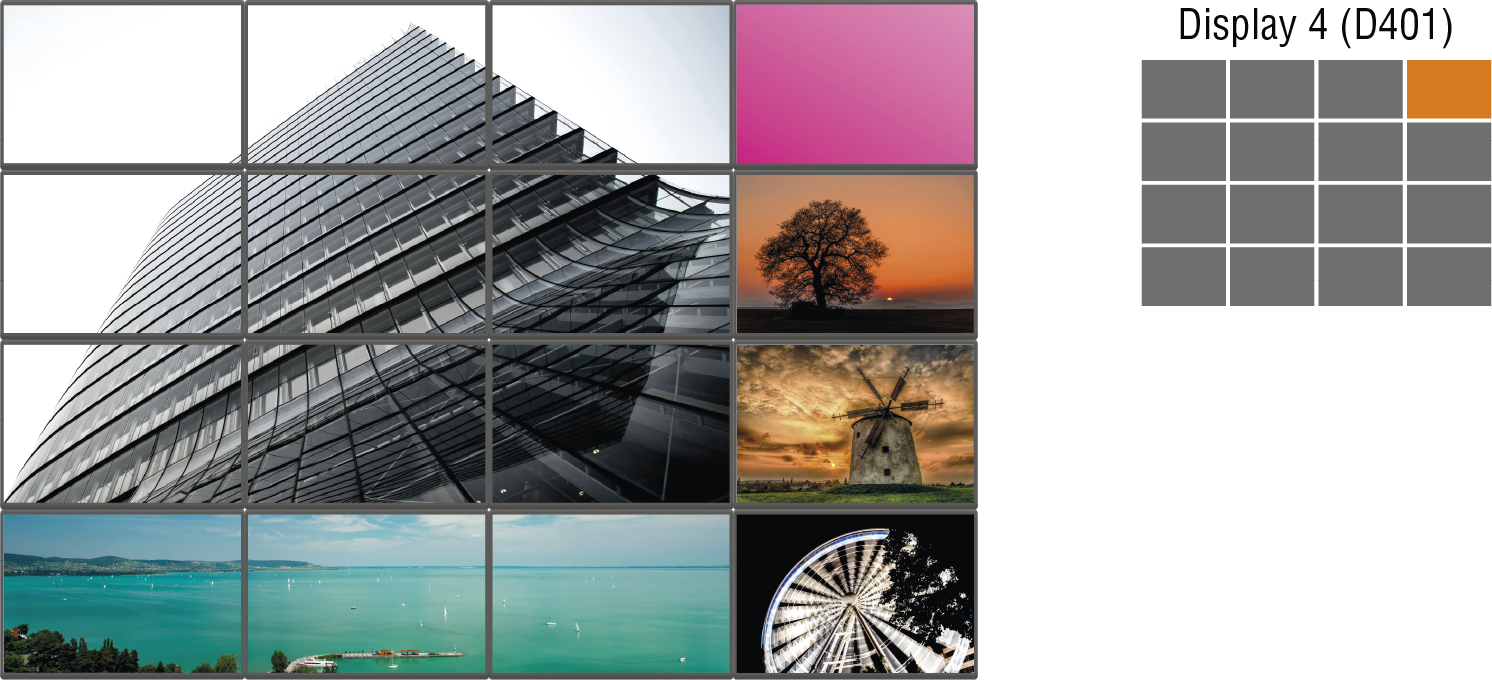
Example for Identifying a Zone

The Identify display/zone feature is available:
▪in the Lightware Device Controller (LDC) software - see the details in the Managing of the Layout and Zones section.
▪with LW3 protocol commands - see the details in the Identify the Zone section.
6.4.4. Software Control Modes of the Video Wall
Video walls can be defined and supervised by two software control method:
▪Lightware Device Controller (LDC) / Built-in Website - see the details in the Video Wall Setup section.
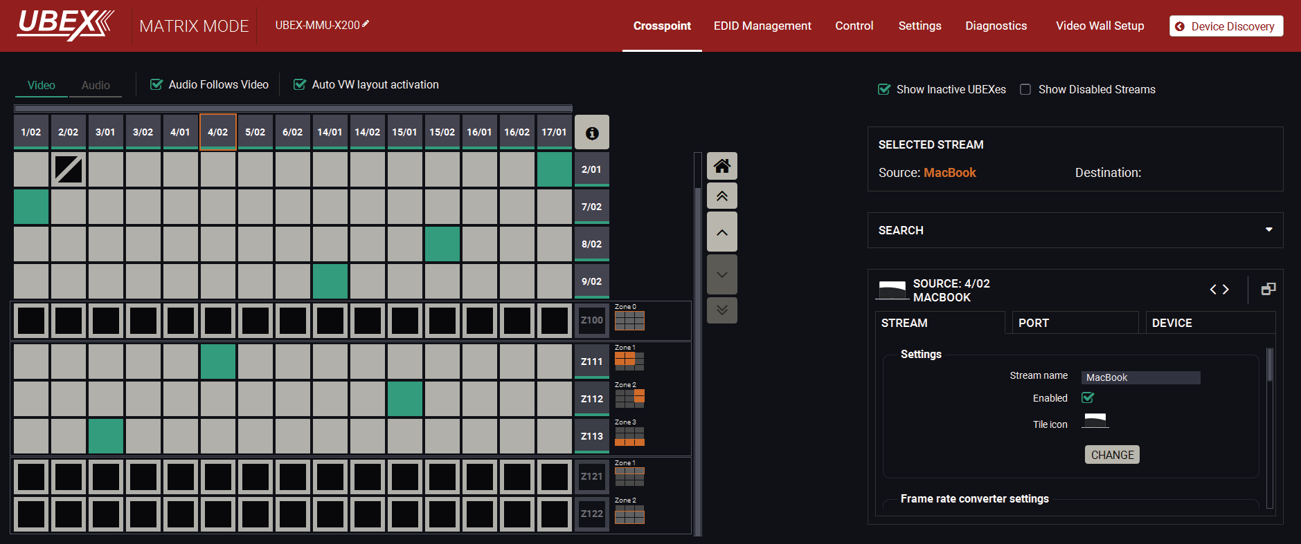
Crosspoint view of the LDC with video wall
▪LW3 protocol commands - see the details in the Video Wall Configuration section.
DIFFERENCE:The fully operational multiviewer operation mode with GUI and centralized fimware package support is available from endpoint firmware package v3.5.1 and MMU firmware package v2.4.3. #multiviewer
UBEX multiviewer is a special operation mode of the endpoint device where video signals from different sources can be displayed on one single sink device ordered by various layouts.
6.5.1. Activation of the Multiviewer Mode
Multiviewer is an operation mode of the endpoint device like transmitter, receiver or transceiver. It can be turned on by the following methods:
▪via Lightware Device Controller (LDC) / Built-in web - see the details in the Device Map section;
▪via LW3 protocol command - see the details in the Set the Operation Mode section.
ATTENTION!This operation requires to reboot the endpoint device.
After the device boots up the endpoint is functioning as a multiviewer.
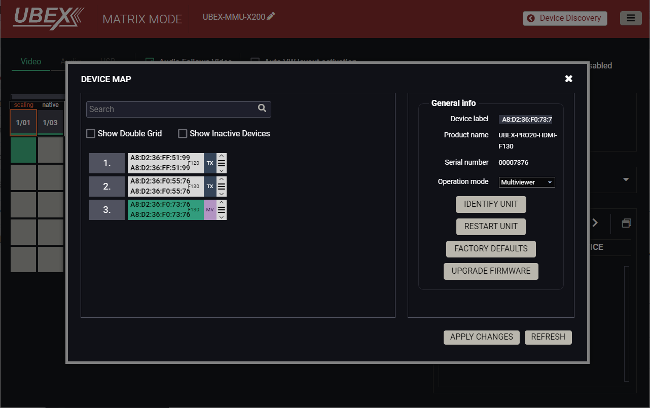
Device map window in the LDC
6.5.2. Definitions
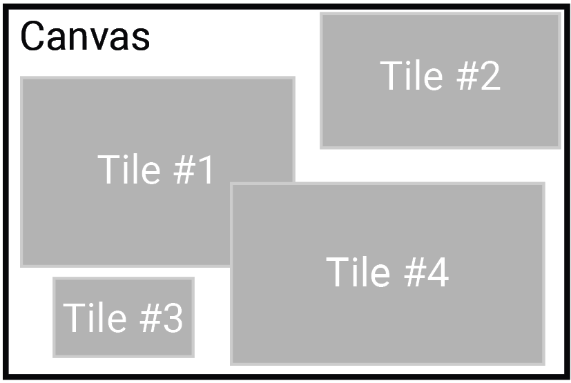
The multiviewer mode brings several new definitions in the user manual. This section is dedicated to clear up all of them.
▪Multiviewer: the multiview video content means several tiles placed on a canvas where one tile contains one video stream.
▪Canvas: the surface where the tiles are located. Its resolution is the same as the resolution of the sink device. In case of UBEX multiviewer, the canvas with the tile(s) cannot be scaled or manipulated on the multiviewer side, but streams can be processed several different way on the transmitter/transceiver side.
▪Tile: the tile contains the video content on the canvas. Up to four tiles can be placed on the canvas in the UBEX multiviewer system. The resolution of the tile must be smaller than the resolution of the canvas. One tile contains one video stream. In case of UBEX multiviewer, the resolution of the stream and the size of the tile must be the same.
Multiview Layouts

▪Basic QUAD multiview: the most common layout of the tiles where four same size tiles are ordered in two rows and two columns, the tiles do not overlap each other and no blank space left in the canvas. In this case the video format must be the same for the four tiles and the canvas (the sink device); as well as the resolution of the tile must be the half of the resolution of the canvas (e.g. if the canvas is 2160p, the tiles must be 1080p).

▪Basic NxM multiview: layout of four tiles where the tiles are ordered in two rows and two columns, they can overlap each other and the video format of the tiles can be different. The empty spaces of the canvas will be filled by black pixels.

▪Picture-by-picture multiview: layout of two equally wide tiles which are placed side-by-side, the tiles can overlap each other and the video format of the tiles can be different. The empty spaces of the canvas will be filled by black pixels.

▪Picture-in-picture multiview: layout of two or more tiles which overlap each other. The size of the foreground tile is always smaller than the background tile's one. There is no pillarbox and letterbox around the foreground tile, its Active and Content have the same resolution. The empty spaces of the canvas will be filled by black pixels.
6.5.3. Description
UBEX multiviewer is a special operation mode of the endpoint device where video signals from different sources can be displayed on one single sink device ordered by various layouts. The key features of the UBEX multiviewer are the following:
▪Handles up to 4 different sources that means up to 2x2 tiles can be placed on the canvas;
▪The Active and the Content of the tiles have the same sizes, which means neither Pillarbox nor Letterbox are defined in the UBEX multiviewer system;
▪Picture-by-picture and picture-in-picture layouts are supported;
▪Tiles can overlap each other;
▪Tiles must be placed within the canvas area, extending beyond the canvas is not supported;
▪Multiviewer supports RGB color space only;
▪In case of HDCP authentication problem of a tile, the whole canvas area will be filled with black pixels;
▪Audio streams can be switched independently in the Audio layer.
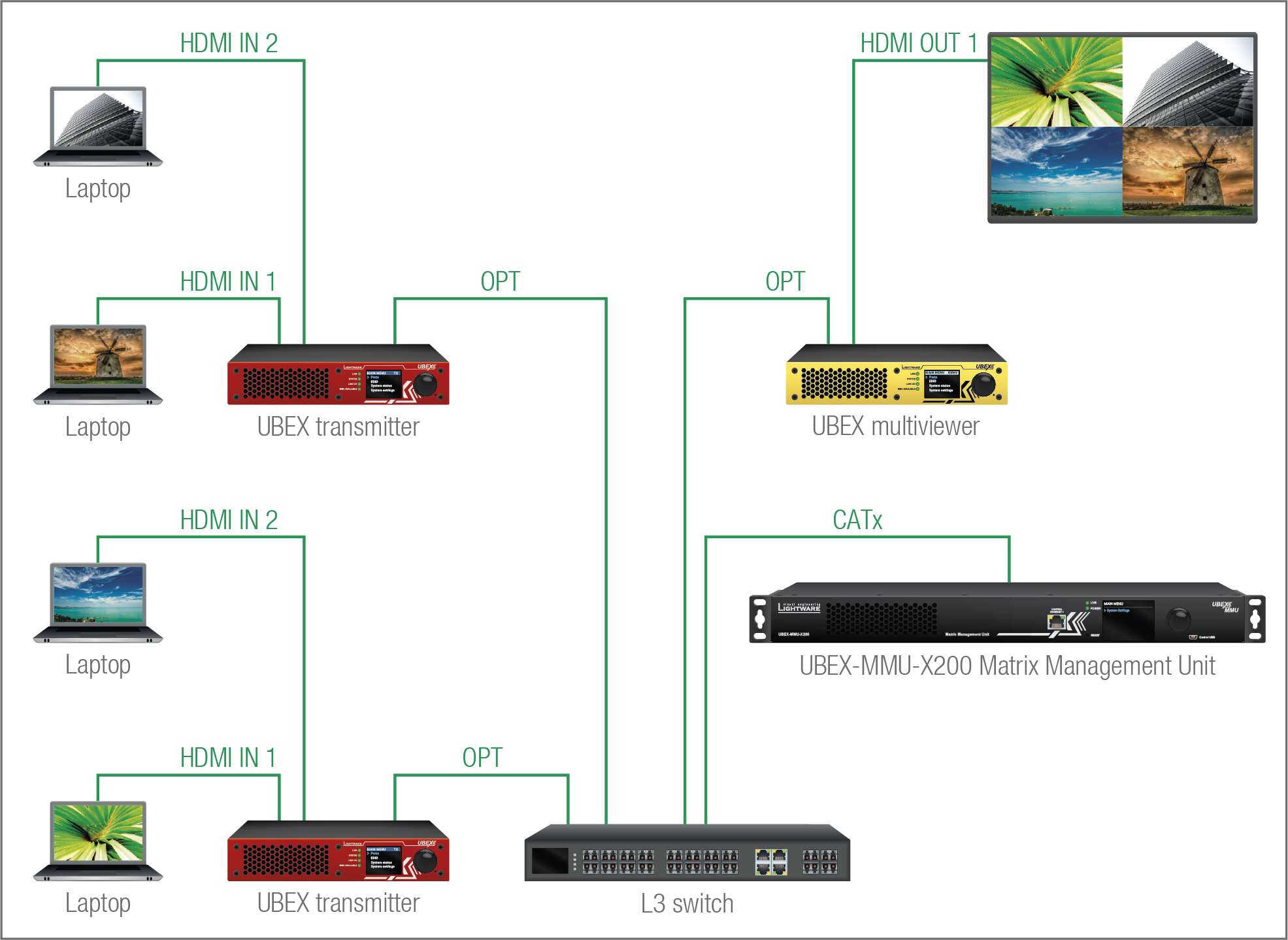
Installation example for the multiviewer feature
The port diagram is valid for the following UBEX endpoint models:
▪UBEX-PRO20-HDMI-F100; -F110; -F111; -F120; -F121; -F130
▪UBEX-PRO20-HDMI-R100 series
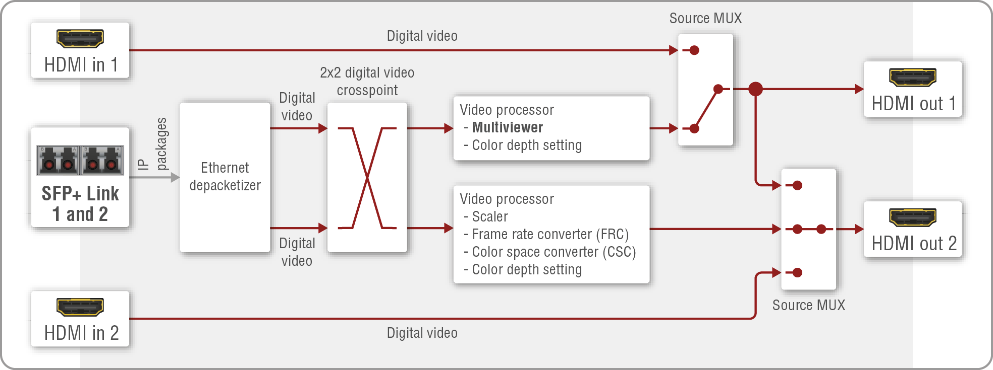
Video port diagram of the F-series and R-series multiviewer
Fiber Optical Interface
The multiviewer can receive up to five HDMI video streams via the fiber optical input ports up to 20 Gbps bandwidth.
HDMI Output Modes
The multiviewer can transmit HDMI video streams on two HDMI 2.0 output ports. The signal can be up to 4K@60 Hz 4:4:4 in the case of both outputs.
ATTENTION!Multiviewer supports RGB color space only.
HDMI Out 1
Up to four video streams can be received from the remote endpoint devices, which can be routed to the HDMI output 1 port and organized into various layouts.
The canvas (including all tile streams) can be processed in the video processor that has color depth setting function.
The multiviewer functions and the color depth setting are available by LW3 protocol commands only, see more details in the Multiviewer Configuration section.
HDMI Out 2
The stream received from the remote endpoint device can be routed to the HDMI output 2.
The streams can be processed in the video processors. The processor of the HDMI 2 has video scaler, frame rate converter (FRC), color space converter (CSC) and color depth setting functions.
Source Multiplexer (MUX)
The source multiplexer (Source MUX) makes routing several different source signals to the HDMI output ports available. The type of sources is different for the two outputs.
HDMI out 1
▪Able to accept up to four signals via the SFP+ links from up to four remote endpoint devices;
▪Able to accept signal up to 4K@60 4:4:4 resolution via the local HDMI in 1 port.
HDMI out 2
▪Able to accept signal up to 4K@60 4:4:4 resolution via the SFP+ links from the remote endpoint device;
▪Able to accept signal up to 4K@60 4:4:4 resolution via the local HDMI in 2 port;
▪Able to copy the signal of the HDMI out 1 port up to 4K@60 4:4:4 resolution. This is the COPY function.
ATTENTION!If the selected source is the local input port or the copy of the HDMI out 1, the output is still selectable as a destination in the global crosspoint table. It means the crosspoint setting is not forbidden for the selected output and it is still included in the bandwidth calculation. When the sum of the two incoming streams exceeds the bandwidth limit, the signal transmission can be denied on the HDMI out 2 port even if the incoming stream of the HDMI out 1 is not used. When the sum of all incoming streams exceeds the bandwidth limit, the signal transmission can be denied on the HDMI out 2 port even if some of the incoming streams of the HDMI out 1 are not used. The solution of this limitation is to disable the unused destination port.
HDMI Input Modes
The HDMI input ports of the multiviewer operate as local HDMI inputs. The stream cannot be affected by any video processing.
Summary Tables
|
HDMI INPUTS |
||
|
HDMI input 1 |
HDMI input 2 |
|
|
Accepted signal |
up to 4K@60 4:4:4 |
up to 4K@60 4:4:4 |
|
Signal sink |
HDMI output 1 |
HDMI output 2 |
|
HDMI OUTPUTS |
|||||
|
HDMI output 1 |
HDMI output 2 |
||||
|
Output signal |
up to 4K@60 4:4:4 |
up to 4K@60 4:4:4 |
|||
|
Signal source |
Source MUX |
Source MUX |
|||
|
Multiviewer input streams (up to four sources) |
Local HDMI input 1 |
Selected input port of the remote device |
Local HDMI input 2 |
Copy of the HDMI output 1 |
|
|
Scaler |
- |
- |
|
- |
- |
|
Frame rate converter (FRC) |
- |
- |
|
- |
- |
|
Color space converter (CSC) |
- |
- |
|
- |
- |
|
Color depth setting |
|
- |
|
- |
- |
6.5.5. Options and Features
The following options and features are available in the UBEX multiviewer system via LW3 protocol commands.
ATTENTION!At recent stage of development the multiviewer features and settings are available by LW3 protocol commands only.
|
Canvas size / resolution |
Enable/disable the tile |
|

|

|
|
|
The resolution of the canvas is equal to the resolution of the sink device. |
The desired tile can be muted and switched on again anytime. |
|
|
Tile position |
Tile size / resolution |
|

|

|
|
|
The position of the tile inside the canvas can be set. The top left corner of the tile is the starter pixel, the required parameters are the horizontal and vertical pixels. Tiles must be placed within the canvas area, extending beyond the canvas is not supported. |
The tile size and the resolution of the input stream must be the same. Tiles must be placed within the canvas area, extending beyond the canvas is not supported. |
|
|
Layer order |
Tile opacity |
|

|

|
|
|
The setting is for re-prioritization of the tile layouts which can use in case of the tiles overlap each other. The priority of the tiles determines which is in front. |
The setting adjusts the opacity of the selected tile. The opacity is in percent, 100% means the stream is not transparent, 0% means the stream is not visible. |
The options and features are available over the following interfaces:
▪Lightware Device Controller (LDC) software - see the details in the Multiviewer Configuration section;
▪LW3 protocol commands - see the details in the Multiviewer Configuration section.
INFO:Learn more details about the multiviewer configuration setup in a detailed step-by-step tutorial in the Multiview Designer - Tutorial section.
6.5.6. Multistream Feature of the Transmitter
DIFFERENCE:The multistream feature for the transmitter is available from firmware version v3.3.0.
The transmitter is able to transmit the processed and the native version of the stream at the same time. There are dedicated stream lines built into the transmitter and the user can decide which one or both together are wanted to be transmitted toward to the sink devices. The feature gives oppurtinity to decide according to the needs of the user.
The feature brings more audio and video ports to the endpoints in all operation modes, please check the Endpoint Port Numbering (Stream ID Calculation) section before set the crosspoint.
ATTENTION!Always check the bandwidth limitation of the endpoints. See the formula to the bandwidth calculation in the Bandwidth Requirements of the Resolutions section.
6.6. Multiview Designer - Tutorial
The following tutorial helps the installation and configuration of the UBEX multiviewer system including useful tips and tricks to optimize your network traffic as well.
6.6.1. Installation
Set the operation mode of the endpoint devices. The source side shall be transmitters (TX) and transceivers (TRX), the sink side is the multiviewer (RXMV). Use the following method to set the RXMV operation mode:
▪via Lightware Device Controller (LDC) / Built-in web - see the details in the Device Map section;
▪via LW3 protocol command - see the details in the Set the Operation Mode section.
The HDMI out 1 port can be used for multiviewer purpose.
See more detailed installation steps and notices in the F-series Endpoints - Multiviewer Operation Mode and the R-series Endpoints - Multiviewer Operation Mode sections.
6.6.2. Configuration
INFO:At recent stage of development the multiviewer features and settings are available by LW3 protocol commands only. See all related commands in the Multiviewer Configuration section.
The following steps are required to configure the multiviewer system. The steps are listed in logical order but they can be interchangeable.
Set the Resolution of the Canvas
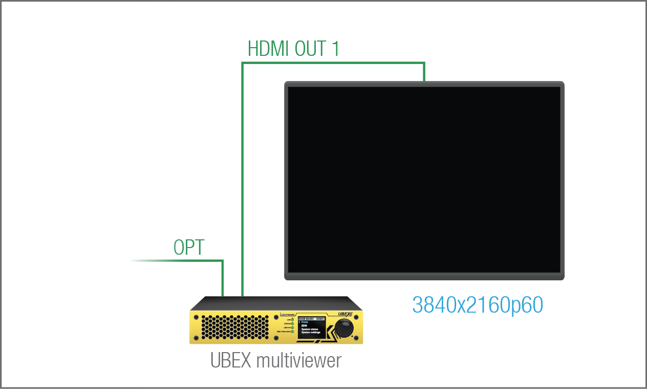
The resolution of the canvas is equal to the resolution of the sink device. For example if the sink where the multiviewer is designed is a 4K UHD monitor, set the canvas size to 3840x2160p60. The canvas size setting of the multiviewer is available via:
▪Lightware Device Controller (LDC) software / Built-in web - see the details in the Layout Settings section;
▪LW3 protocol command - see the details in the Setting the Resolution of the Canvas section.
Set the Resolution of the Source Streams
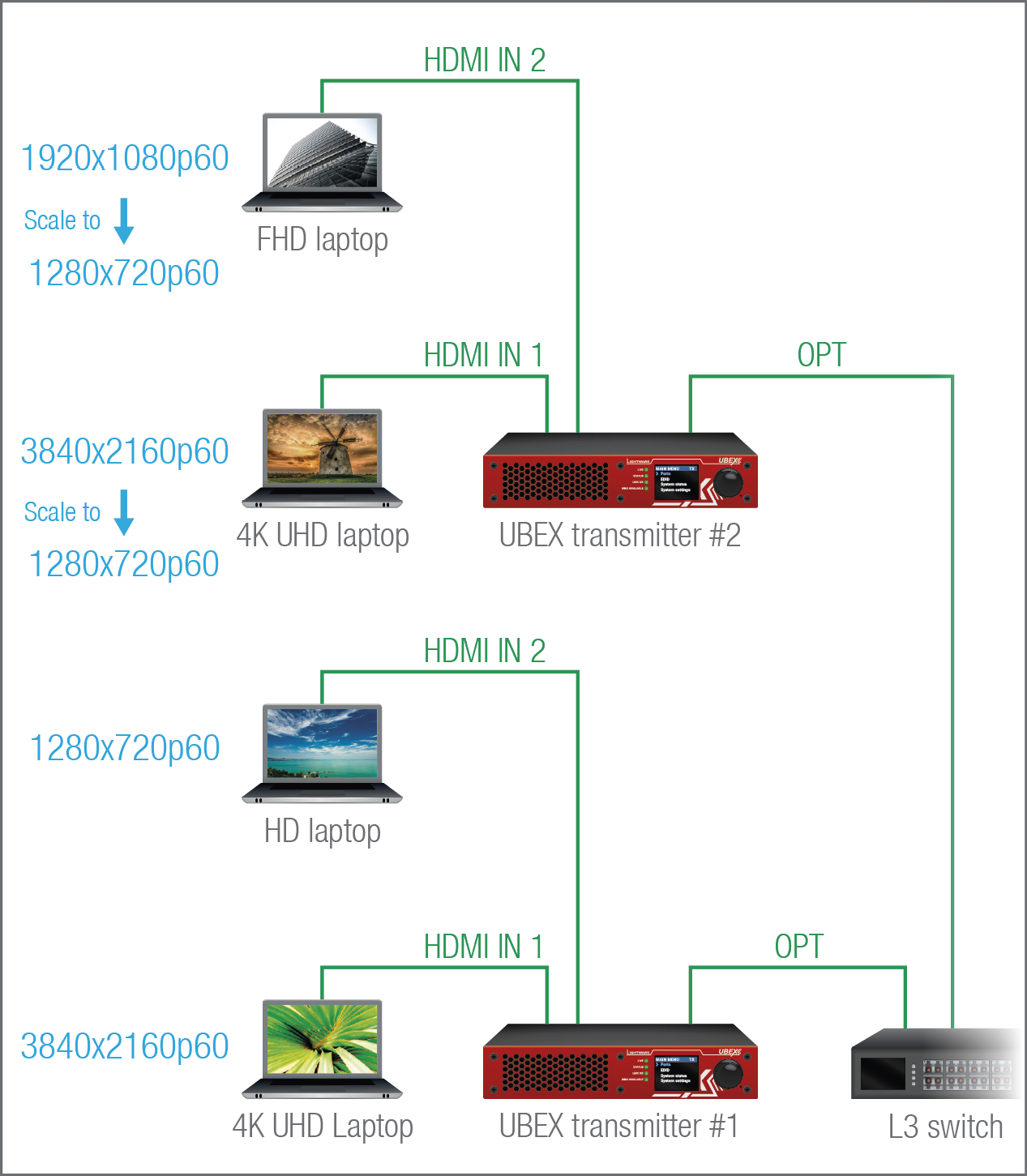
Four source streams per multiviewer can be received from the transmitter side which can be processed by the UBEX transmitter before they are transmitted to the multiviewer.
This example presents a picture-in-picture multiviewer layout where there is a background and three foreground streams on the multiviewer sink. Altogether four source devices are connected to two transmitters: a FHD laptop, two 4K UHD capable laptops and an HD laptop.
In our example the size of the foreground tiles will be 1280x720 for all foreground streams so three streams need to be scaled to 1280x720p60. The scaler setting of the transmitter is available via:
▪Lightware Device Controller (LDC) software - see the details in the Video Source Port Properties Window section;
▪LW3 protocol command - see the details in the Resolution Mode Setting and the Tile Resolution Setting sections.
Optimize the Source Streams
The 20G connection between the endpoints is enough to build a basic quad multiview system with 4x 1080p streams (4x 3.23 Gpbs) or like in our example, a 4K UHD background and 3x 720p foreground streams. If the network traffic needs to be optimized, UBEX transmitter provides several possibilities for processing the AV signal, which can result in reduced signal bandwidths.
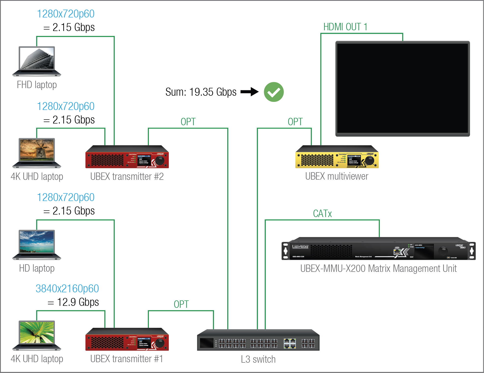
|
Stream |
Device |
Resolution and refresh rate |
Color sampling |
Color depth |
Required bandwidth |
|---|---|---|---|---|---|
|
Stream 1 |
TX #1 |
3840x2160@60Hz |
4:4:4 |
24 bit (8 bit/ch) |
12.9 Gbps |
|
Stream 2 |
TX #1 |
1280x720@60Hz |
4:4:4 |
36 bit (12 bit/ch) |
2.15 Gbps |
|
Stream 3 |
TX #2 |
1280x720@60Hz |
4:4:4 |
36 bit (12 bit/ch) |
2.15 Gbps |
|
Stream 4 |
TX #2 |
1280x720@60Hz |
4:4:4 |
36 bit (12 bit/ch) |
2.15 Gbps |
Bandwidth Error

If the bandwidth of the source streams is out of the range, the tiles will not be displayed on the canvas and the tile status will be "BandwidthError".
The actual status of the tile of the multiviewer is available via:
▪Lightware Device Controller (LDC) software / Built-in web - see the details in the Crosspoint Menu section;
▪LW3 protocol command - see the details in the Querying the Status of the Tile section.
Optimalization and Signal Processing
The transmitter has a built-in scaler with color depth converter on both input ports. The following signal processing can be applied on the streams to reduce the required bandwidth:
|
Stream |
Device |
Resolution and refresh rate |
Color sampling |
Color depth |
Required bandwidth |
|---|---|---|---|---|---|
|
Stream 1 |
TX #1 |
3840x2160@60Hz |
4:4:4 |
24 bit (8 bit/ch) |
12.9 Gbps |
|
Stream 2 |
TX #1 |
1280x720@60Hz |
4:4:4 |
24 bit (8 bit/ch) |
1.43 Gbps |
|
Stream 3 |
TX #2 |
1280x720@60Hz |
4:4:4 |
24 bit (8 bit/ch) |
1.43 Gbps |
|
Stream 4 |
TX #2 |
1280x720@60Hz |
4:4:4 |
24 bit (8 bit/ch) |
1.43 Gbps |
The sum of bandwidths of the four streams is 17.19 Gbps, it's a saving of more than 2G on the network traffic.
The color depth converter of the transmitter is available via:
▪Lightware Device Controller (LDC) software - see the details in the Video Source Port Properties Window section;
▪LW3 protocol command - see the details in the Color Depth Setting section.
Crosspoint Settings
The crosspoint setting is available via:
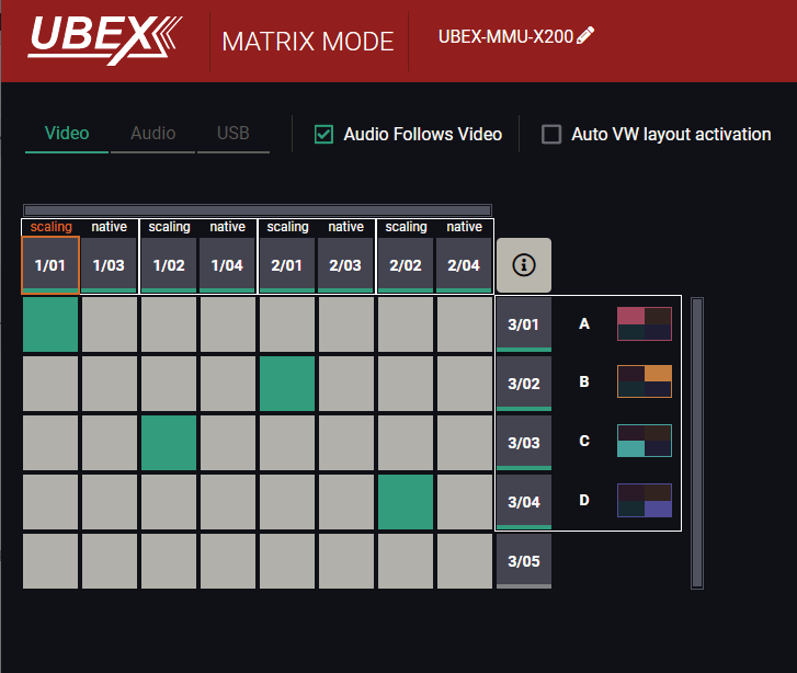
▪Lightware Device Controller (LDC) software - see the details in the Crosspoint Menu section;
▪LW3 protocol command - see the details in the Switching the Video Stream to One Destination section.
Set the Tile Sizes
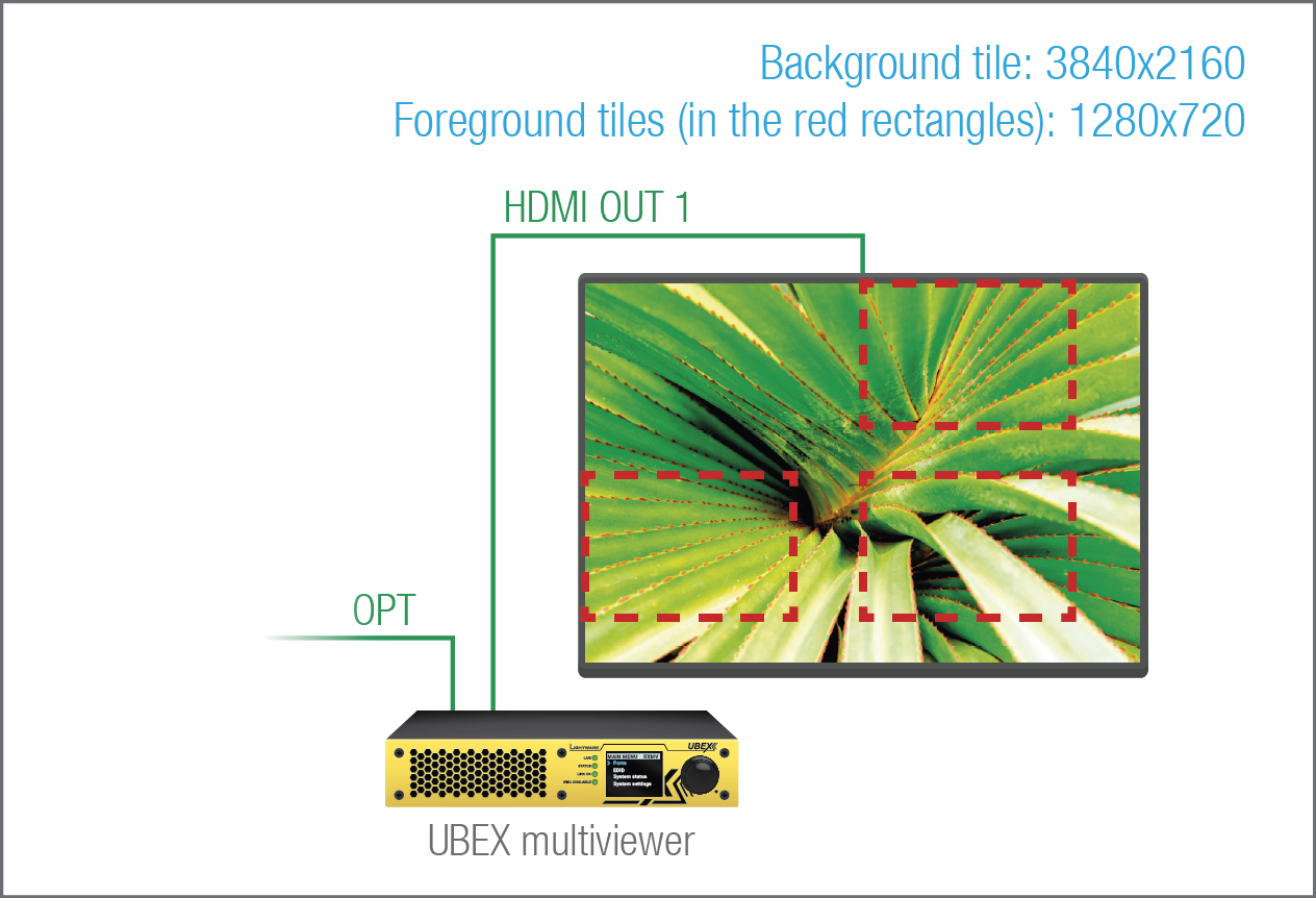
Four tiles can be placed on the canvas for the four source streams.
ATTENTION!The size of the tiles must be the same as the resolution of the streams.
If the resolution of the tile and the source stream is not equal, the tile will not be displayed on the canvas and the tile status will be "InvalidSize".
The tile size setting of the multiviewer is available via:
▪Lightware Device Controller (LDC) software - see the details in the Layout Settings section;
▪LW3 protocol command - see the details in the Tile Size Setting section.
The actual status of the tile in the multiviewer is available via:
▪LW3 protocol command - see the details in the Querying the Status of the Tile section.
Why the foreground tiles do not appear on the canvas? They appear but located behind the background tile. The layout of the tiles needs to be rearranged - the next section describes the method.
Reorder the Layout of the Tiles
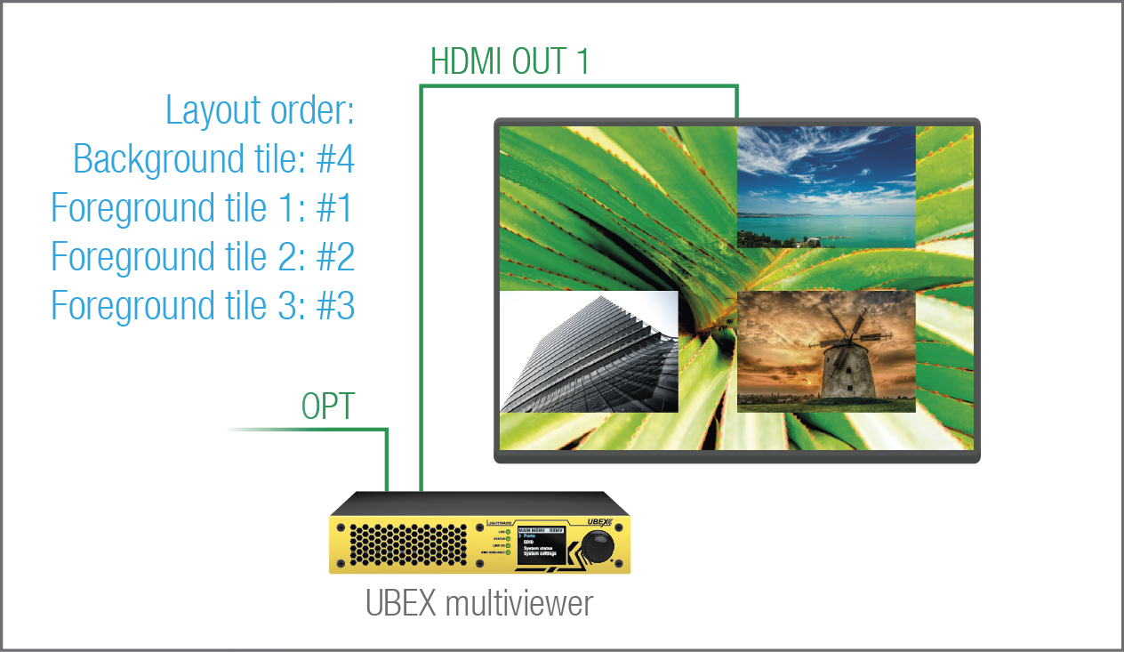
The prioritization of the tiles determines which is in front. The default priority is the #1 is first tile (T1 - this is the background tile in our example), the #2, #3 and #4 are the foreground tiles (T2, T3 and T4 - these are the foreground tile in our example). The lower number means the front location of the tile so the T1 needs to be set as the #4.
The layout order setting of the multiviewer is available via:
▪Lightware Device Controller (LDC) software - see the details in the Layout Settings section;
▪LW3 protocol command - see the details in the Layer Order Setting section.
Set the Position of the Tile
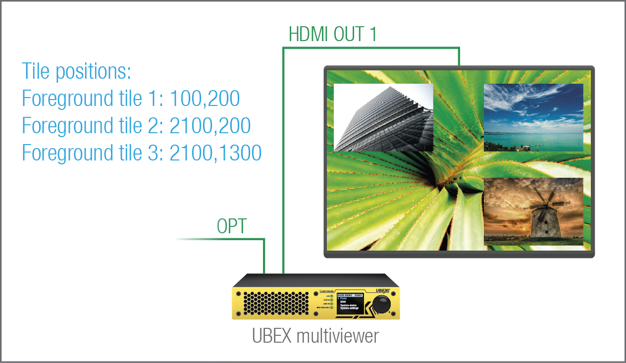
The default positions of the tiles are the following:
▪T1 (background tile): 0,0
▪T2: 1920,0
▪T3: 0,1080
▪T4: 1920,1080
The formula of the tile position is: horizontal_pixel,vertical_pixel
In our example the foreground tiles should be rearranged to look better.
The tile position setting of the multiviewer is available via:
▪LW3 protocol command - see the details in the Tile Position Setting section.
ATTENTION!Tiles must be placed within the canvas area, extending beyond the canvas is not supported.
If a part of the tile is located beyond the canvas area, the tile will not be displayed and the tile status will be "InvalidPosition".
The actual status of the tile of the multiviewer is available via:
▪Lightware Device Controller (LDC) software - see the details in the Layout Settings section;
▪LW3 protocol command - see the details in the Querying the Status of the Tile section.
Optionally - Set the Opacity of the Tile or Enable/Disable It
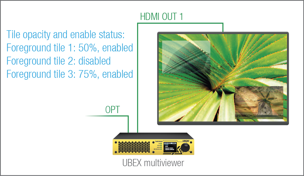
The setting adjusts the opacity of the selected tile. The opacity value is in percent, 100% means the stream is not transparent, 0% means it is not visible.
Also a tile can be disabled or enabled again in the multiviewer system.
The tile opacity setting of the multiviewer is available via:
▪Lightware Device Controller (LDC) software - see the details in the Layout Settings section;
▪LW3 protocol command - see the details in the Tile Opacity Setting section.
The enable/disable setting of the tiles of the multiviewer is available via:
▪Lightware Device Controller (LDC) software - see the details in the Layout Settings section;
▪LW3 protocol command - see the details in the Enabling/Disabling the Tile section.
6.7.1. Transmitter Mode - F100 / R100 Models
Port Diagram
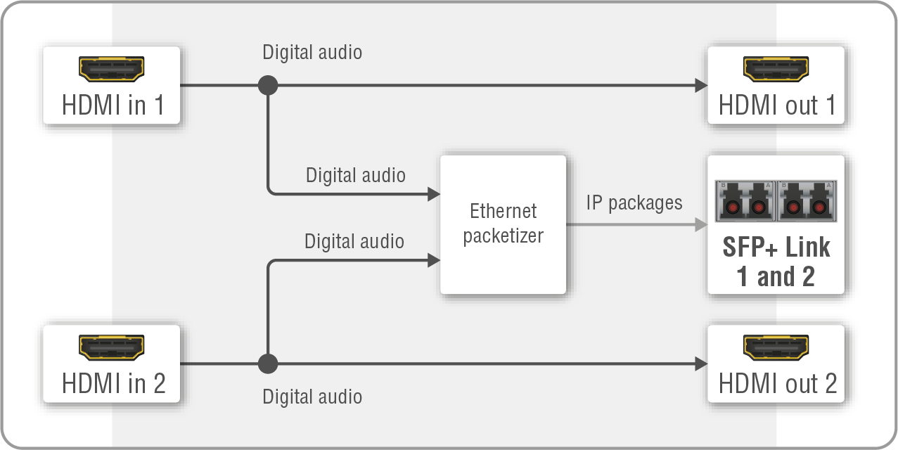
The port diagram is valid for the following UBEX endpoint model:
▪UBEX-PRO20-HDMI-F100
▪UBEX-PRO20-HDMI-R100 series
Description
The transmitter receives HDMI audio signals via the two HDMI input ports. The audio streams are transmitted toward the remote endpoint device over the SFP+ links. The two source streams can be selected to any output port on the destination side. The crosspoint settings are supervised by the MMU.
The HDMI output ports of the transmitter are HDMI loop-back ports and can be used as local HDMI outputs.
6.7.2. Receiver Mode - F100 / R100 Models
Port Diagram
The port diagram is valid for the following UBEX endpoint model:
▪UBEX-PRO20-HDMI-F100
▪UBEX-PRO20-HDMI-R100 series
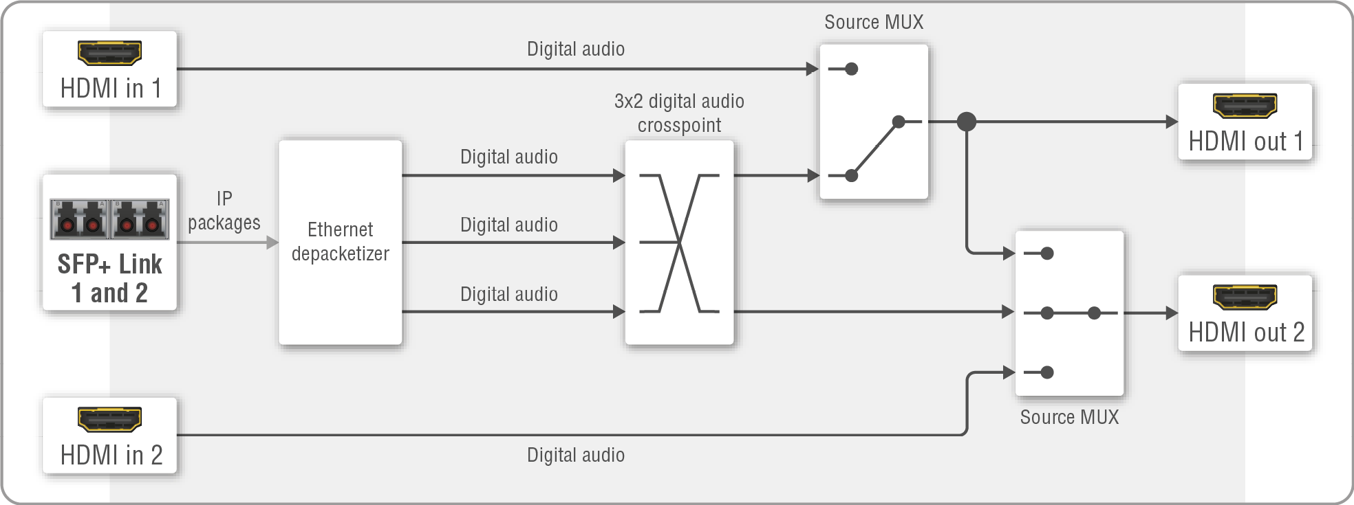
Audio port diagram of the F100/R100 receiver
Description
The receiver receives two HDMI audio streams via the SFP+ links. The streams can be selected to any HDMI output ports, the crosspoint settings are available in the MMU.
Source Multiplexer (MUX)
INFO:The source MUX function can be set on the video side only in the Lightware Device Controller (LDC) software, and using LW3 protocol commands as well.
The source multiplexer (Source MUX) makes routing several different source signals to the HDMI output ports available. The type of sources is different by the two outputs.
HDMI out 1
▪Able to accept audio signal via the SFP+ links from the remote endpoint device;
▪Able to accept audio signal via the local HDMI in 1 port.
HDMI out 2
▪Able to accept audio signal via the SFP+ links from the remote endpoint device;
▪Able to accept audio signal via the local HDMI in 2 port;
▪Able to copy the signal of the HDMI out 1 port. This is the COPY function.
HDMI Input Modes
The HDMI input ports of the receiver operate as local HDMI inputs.
6.7.3. Transceiver Mode - F100 / R100 Models
Port Diagram
The port diagram is valid for the following UBEX endpoint model:
▪UBEX-PRO20-HDMI-F100
▪UBEX-PRO20-HDMI-R100 series
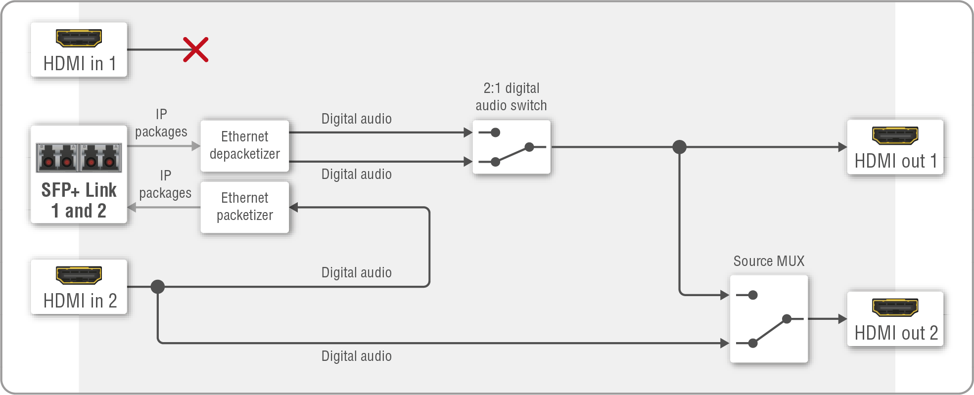
Audio port diagram of the F100 transceiver
Description
The transceiver receives one HDMI audio stream via the SFP+ links and transmitting on the HDMI out 1 port. The source signal can be any audio streams from the source side, the crosspoint settings are supervised by the MMU.
The transceiver receives an HDMI audio signal via the HDMI input 2 port. The audio stream is transmitted toward the destination side over the SFP+ links. The crosspoint settings are supervised by the MMU.
The local HDMI output port (HDMI out 2) is HDMI loop-back port and source is always the HDMI in 2 port.
The HDMI input 1 port of the transceiver cannot accept audio signals due to software limitation.
Source Multiplexer (MUX)
INFO:The source MUX function can be set on the video side only in the Lightware Device Controller (LDC) software, and using LW3 protocol commands as well.
The source multiplexer (Source MUX) makes routing several different source signals to the HDMI output 2 port available.
HDMI out 2
▪Able to accept audio signal via the local HDMI in 2 port;
▪Able to copy the signal of the HDMI out 1 port. This is the COPY function.
6.7.4. Transmitter Mode - F110/F111/F120/F121/F130 Models
Port Diagram
The port diagram is valid for the following UBEX endpoint model:
▪UBEX-PRO20-HDMI-F110; -F111; -F120; -F121; -F130
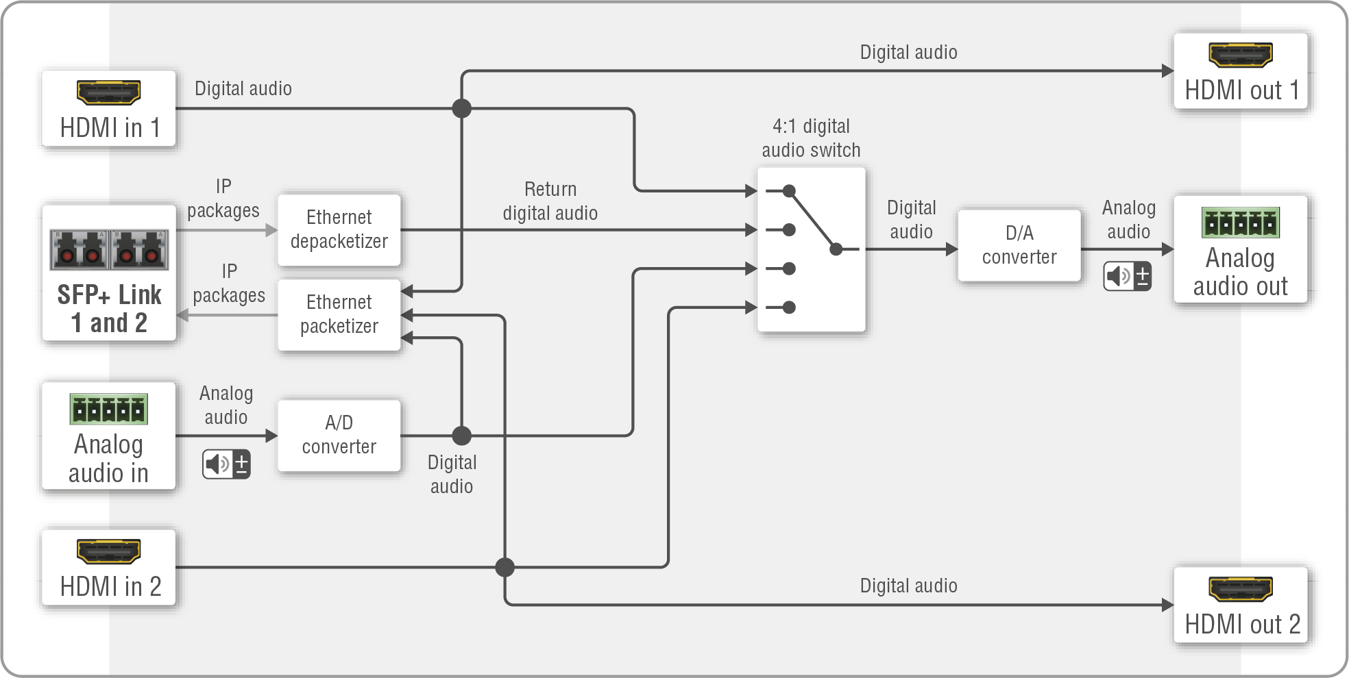
Audio port diagram of the F110 / F120 / F130 transmitter
Description
The device is built with a 4:1 digital audio switch, which has four inputs: the de-embedded digital audio streams of the HDMI in 1 and 2; the analog audio of the analog audio input port; and the return audio channel received from the connected endpoint device over the SFP+ ports. The selected audio stream can be switched to the analog audio out port after a digital/analog conversion (D/A converter).
The audio streams of the HDMI in 1, HDMI in 2, and the analog audio in ports are transmitted via the SFP+ output ports.
The HDMI out 1 and 2 ports are local output ports, they transmit the audio streams of the HDMI in 1 and 2 ports directly.
Signal Support of the Analog Audio Output
The UBEX-PRO20-HDMI-F110, -F111, -F120, -F121 and -F130 endpoint models convert the uncompressed stereo audio stream to analog audio. The analog audio output port supports PCM audio format up to 48 kHz.
ATTENTION!If unsupported audio signal is selected to the analog audio output, the port will be muted automatically. The current status of the port can be queried by an LW3 protocol command, see the details in the Query the Status of the Analog Audio Output section.
6.7.5. Receiver Mode - F110/F111/F120/F121/F130 Models
Port Diagram
The port diagram is valid for the following UBEX endpoint model:
▪UBEX-PRO20-HDMI-F110; -F111; -F120; -F121; -F130
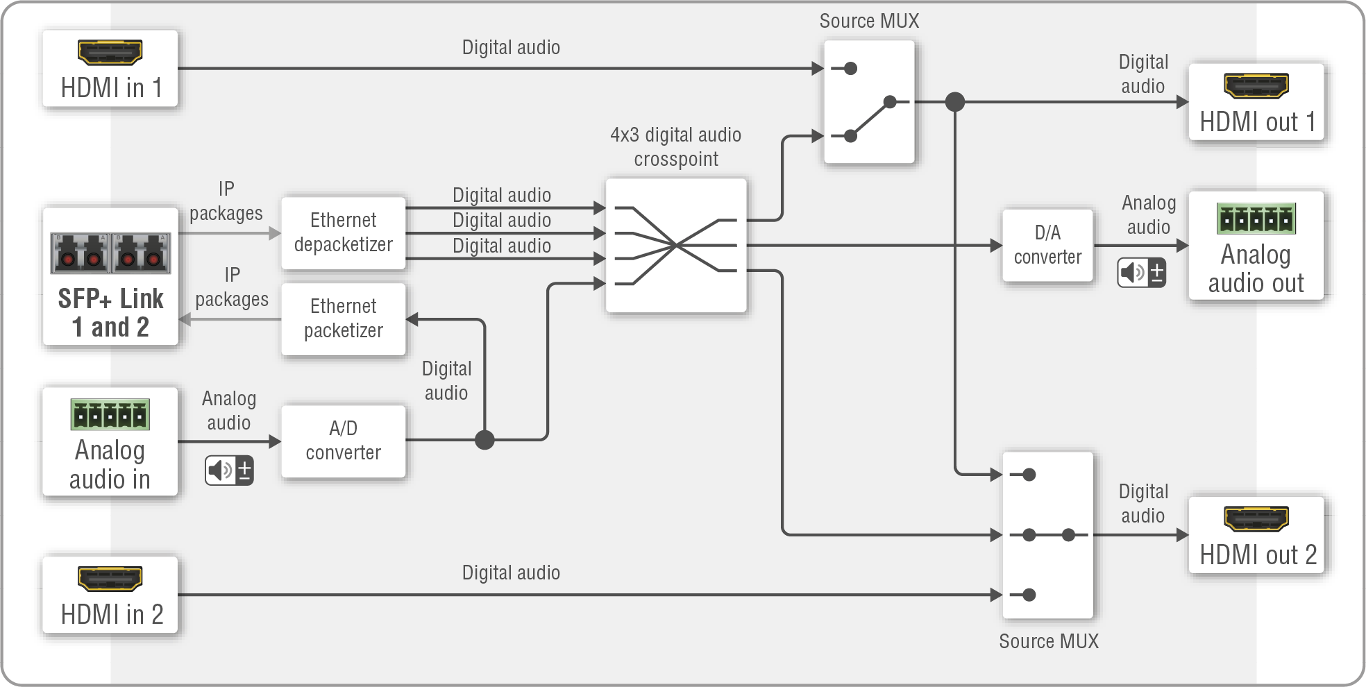
Port diagram of the F110 / F111 / F120 / F121 / F130 receiver
Description
The device is built with a 4x3 digital audio crosspoint, which has four inputs: three digital audio streams are received from the SFP+ links, the fourth input is the stream of the analog audio in port. The audio streams can be selected to the HDMI out 1 and 2, and the analog audio out ports.
The stream of the analog audio in port is transmitted over the SFP+ links.
The HDMI input ports do not accept signals when the device is configured as receiver.
Source Multiplexer (MUX)
INFO:The source MUX function can be set on the video side only in the Lightware Device Controller (LDC) software, and using LW3 protocol commands as well.
The source multiplexer (Source MUX) makes routing several different source signals to the HDMI output ports available. The type of sources is different by the two outputs.
HDMI out 1
▪Able to accept audio signal via the SFP+ links from the remote endpoint device;
▪Able to accept audio signal via the local HDMI in 1 port.
HDMI out 2
▪Able to accept audio signal via the SFP+ links from the remote endpoint device;
▪Able to accept audio signal resolution via the local HDMI in 2 port;
▪Able to copy the signal of the HDMI out 1 port. This is the COPY function.
HDMI Input Modes
The HDMI input ports of the receiver operate as local HDMI inputs.
Signal Support of the Analog Audio Output
The UBEX-PRO20-HDMI-F110, -F111, -F120, -F121 and -F130 endpoint models convert the uncompressed stereo audio stream to analog audio. The analog audio output port supports PCM audio format up to 48 kHz.
ATTENTION!If unsupported audio signal is selected to the analog audio output, the port will be muted automatically. The current status of the port can be queried by an LW3 protocol command, see the details in the Query the Status of the Analog Audio Output section.
6.7.6. Transceiver Mode - F110/F111/F120/F121/F130 Models
Port Diagram
The port diagram is valid for the following UBEX endpoint model:
▪UBEX-PRO20-HDMI-F110; -F111; -F120; -F121; -F130
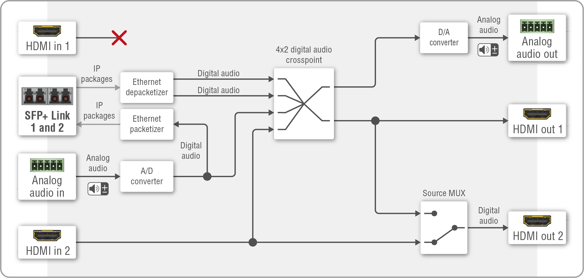
Port diagram of the F110 / F111 / F120 / F121 / F130 transceiver
Description
The device is built with a 4x2 digital audio crosspoint, which has four inputs: two of them are received on the SFP+ links; the stream of the analog audio in, and the stream of the HDMI in 2 port. Any audio can be selected to the HDMI out 1 and the analog audio out ports.
The audio streams of the HDMI in 2 and the analog audio in ports are transmitted via the SFP+ output ports.
The HDMI out 2 port is a local output port, it transmits the audio stream of the HDMI in 2 port directly.
The HDMI input 1 port does not accept signal when the device is configured as transceiver.
Source Multiplexer (MUX)
INFO:The source MUX function can be set on the video side only in the Lightware Device Controller (LDC) software, and using LW3 protocol commands as well.
The source multiplexer (Source MUX) makes routing several different source signals to the HDMI output 2 port available.
HDMI out 2
▪Able to accept audio signal via the local HDMI in 2 port;
▪Able to copy the signal of the HDMI out 1 port. This is the COPY function.
Signal Support of the Analog Audio Output
The UBEX-PRO20-HDMI-F110, -F111, -F120, -F121 and -F130 endpoint models convert the uncompressed stereo audio stream to analog audio. The analog audio output port supports PCM audio format up to 48 kHz.
ATTENTION!If unsupported audio signal is selected to the analog audio output, the port will be muted automatically. The current status of the port can be queried by an LW3 protocol command, see the details in the Query the Status of the Analog Audio Output section.
6.7.7. Audio Signal Transmission - Example
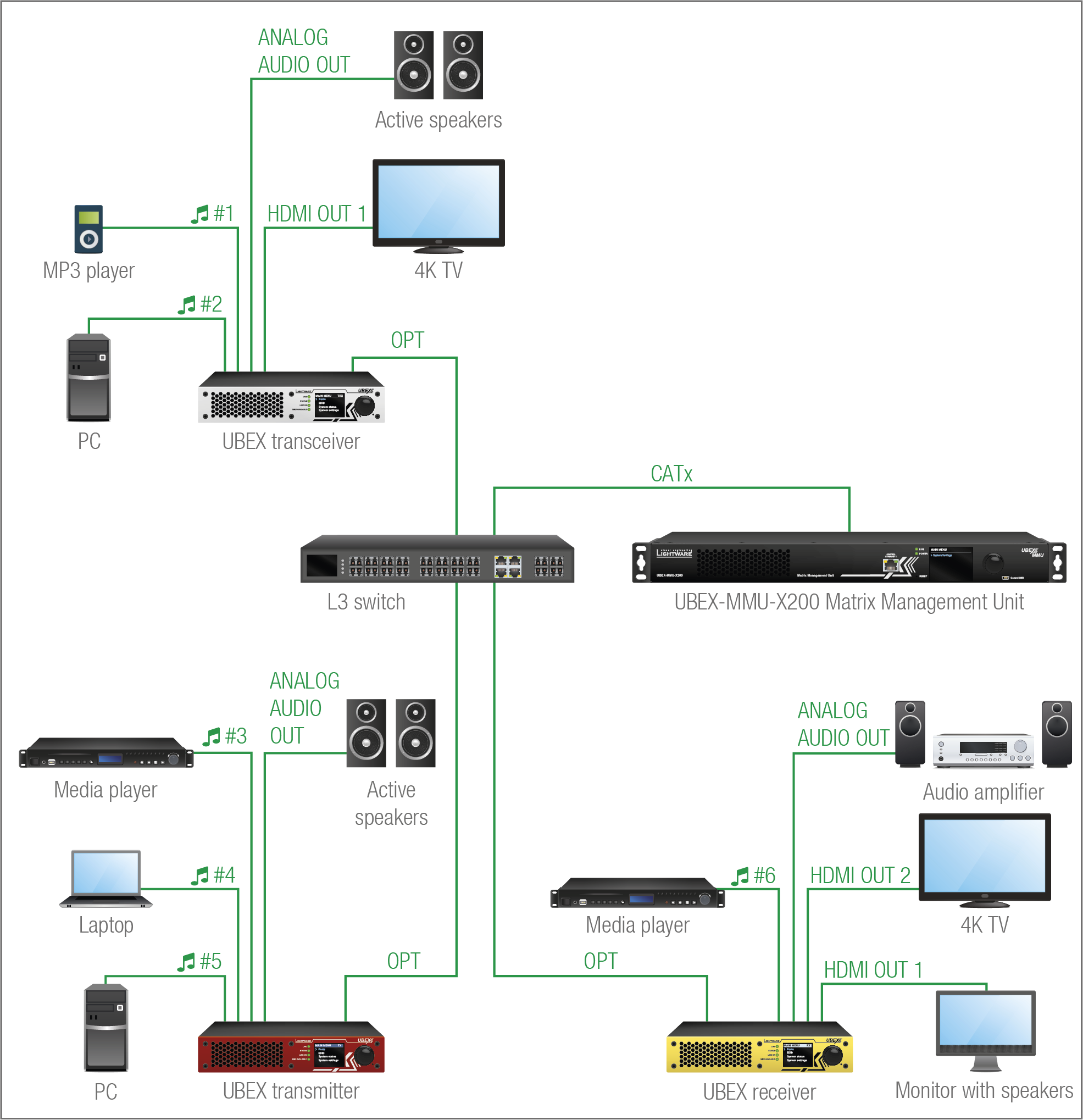
The Concept
This example shows a 6x6 audio matrix with an L3 network switch and the MMU in its center. The matrix contains 6 inputs ( #1..6, mixed digital and analog audio streams) and 6 outputs (mixed digital and analog sink devices). The MMU builds up the crosspoints and controls the AV system.
The following table shows the available crosspoint possibilities:
|
Crosspoint possibilities of the audio streams for the UBEX matrix |
Sink devices |
||||||||
|
TRX |
TX |
RX |
|||||||
|
Active speakers |
4K TV |
Active speakers |
Audio amplifier |
4K TV |
Monitor with speakers |
||||
|
Sources |
TRX |
MP3 player |
|
|
|
|
|
|
|
|
PC |
|
|
|
|
|
|
|
||
|
TX |
Media player |
|
|
|
|
|
|
|
|
|
Laptop |
|
|
|
|
|
|
|
||
|
PC |
|
|
|
|
|
|
|
||
|
RX |
Media player |
|
|
|
|
|
|
|
|
Summary: All audio streams of the source devices can be selected to all sink devices except the local HDMI outputs of the transmitter, which can be always selected to the inputs; and the local HDMI inputs of the receiver, which can be always selected to the outputs.
This section is about the serial interface of the endpoint device.
DIFFERENCE:Only the UBEX-PRO20-HDMI-F110, -F111, -F120, -F121 and F130 models are built with serial interface port.
6.8.1. Technical Background
Port Diagram
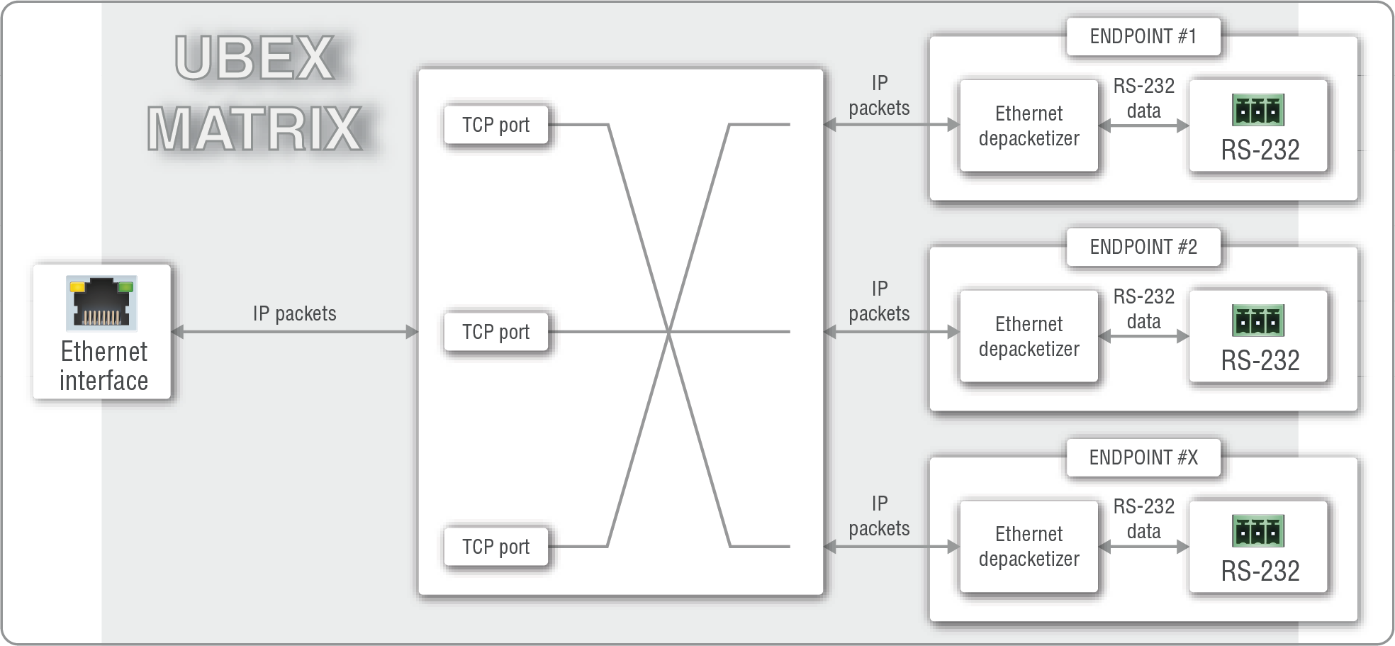
Port diagram of the serial interface for the UBEX matrix
The Concept
The endpoint device uses command injection, which means in the practice it works as a TCP/IP -> RS-232 converter so the TCP/IP data signal is converted to RS-232 data. The serial message is sent over the Ethernet interface. A TCP port in the MMU addresses an RS-232 port in the endpoint device. The user can set which TCP port is ordered to the required RS-232 port.
INFO:It does not matter which device of the Ethernet interface (the MMU directly or any endpoints) you want to use establishing connection with the UBEX matrix, you will reach the MMU finally.
Setting up the TCP Ports of the Serial Interface
The default starting port number is 8000 and increases with one until the number of the RS-232 ports in the matrix. If these TCP ports are reserved in the network, the port numbers can be changed in LDC (see the details in the RS-232 Tab section) or using LW3 protocol command (see the details in the Command Injection TCP Port Setting section).
TIPS AND TRICKS:The TCP ports can be remapped with a single LW3 protocol command, see the details in the Remap the Command Injection TCP ports section.
6.8.2. RS-232 Signal Transmission – Example
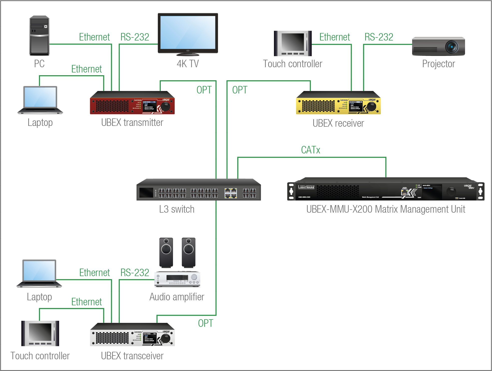
The Concept
The devices which are connected via RS-232 (4K TV, projector, audio amplifier) are controlled with serial messages which are sent over Ethernet interface. All Ethernet devices can send messages to all controlled devices. Up to three Ethernet devices can be connected per endpoints.
You can send serial messages using two methods:
▪Lightware Device Controller (LDC) / Built-in Website - see the details in the RS-232 Tab section;
▪LW3 protocol commands - see the details in the Message Sending via Communication Ports section.
This section is about the Infrared interface of the endpoint device.
DIFFERENCE:Only the UBEX-PRO20-HDMI-F110 and F120 models have built with IR interface ports.
ATTENTION!The device has no built-in Infrared receiver and transmitter. For the complete usage, attach the supplied IR emitter unit to the IR OUT and the IR detector unit to the IR IN connectors.
6.9.1. Technical Background
Port Diagram
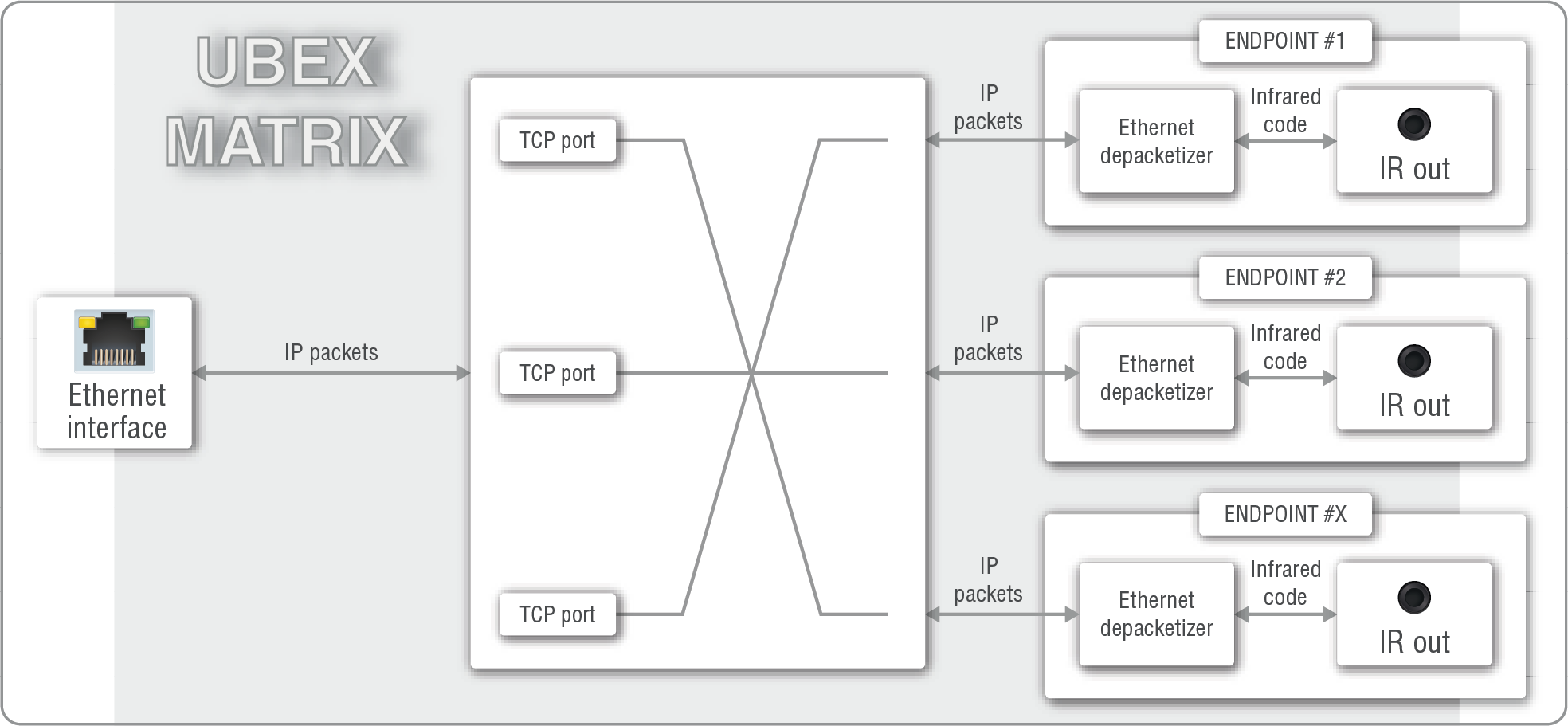
Port diagram of the Infrared interface for the UBEX matrix
The Concept
The endpoint device uses command injection, which means in the practice it works as a TCP/IP -> Infrared converter, so the TCP/IP data signal is converted to Infrared code. The IR message is sent over the Ethernet interface. A TCP port in the MMU is addressed an Infrared output port in the endpoint device. The user can set which TCP port is ordered to the required Infrared output port.
INFO:It does not matter which device of the Ethernet interface (the MMU directly or any endpoints) you want to use establishing connection with the UBEX matrix, you will reach the MMU finally.
Setting up the TCP Ports of the IR Interface
The default starting port number is 9000 and increases with one until the number of the IR ports in the matrix. If these TCP ports are reserved in the network, the port numbers can be changed in LDC (see the details in the Infra Tab section) or using LW3 protocol command (see the details in the Message Sending via Communication Ports section).
6.9.2. Infrared Signal Transmission – Example
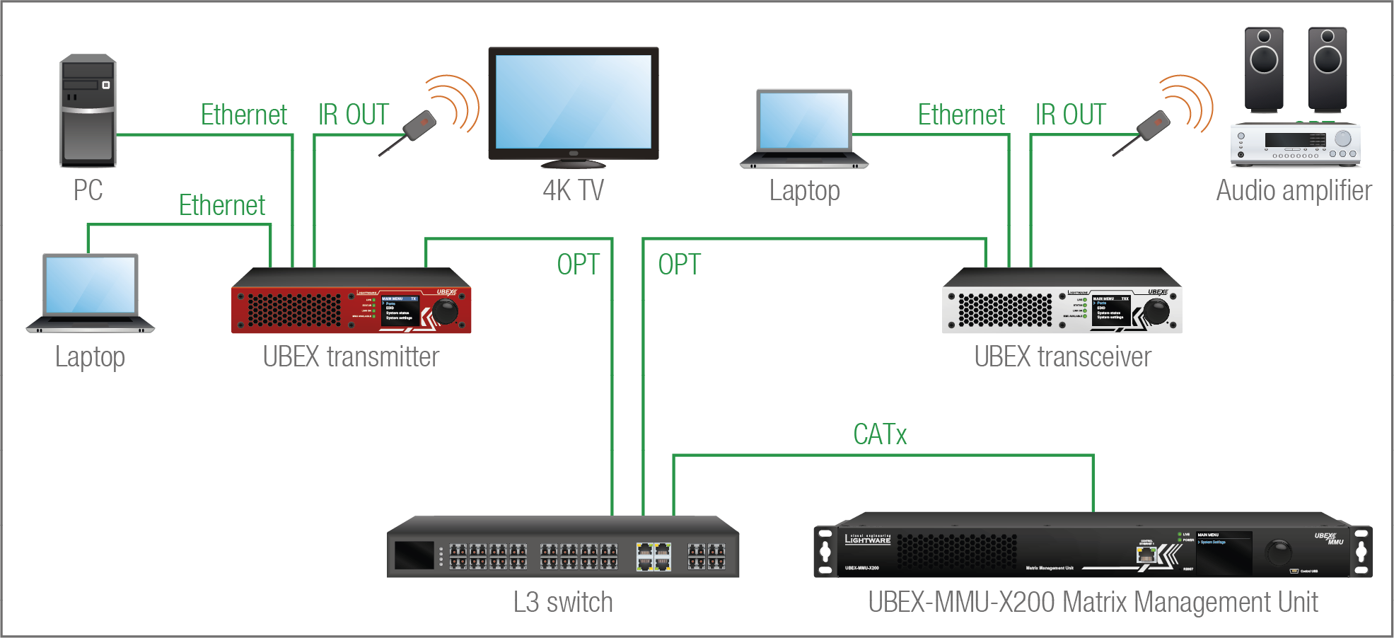
The Concept
The devices which have built-in IR detector (4K TV, audio amplifier) are controlled with Infrared messages which are sent over Ethernet interface. All Ethernet devices can send messages to all controlled devices. Up to three Ethernet devices can be connected per endpoints.
You can send IR messages using two methods:
▪Lightware Device Controller (LDC) / Built-in Website - see the details in the Infra Tab section;
▪LW3 protocol commands - see the details in the Message Sending via Communication Ports section.
6.10. USB K+M Interface (F120 / F121 Models)
DIFFERENCE:Only UBEX-PRO20-HDMI-F120 and -F121 endpoint models are built with USB K+M ports.
6.10.1. Technical Background
Port Diagram
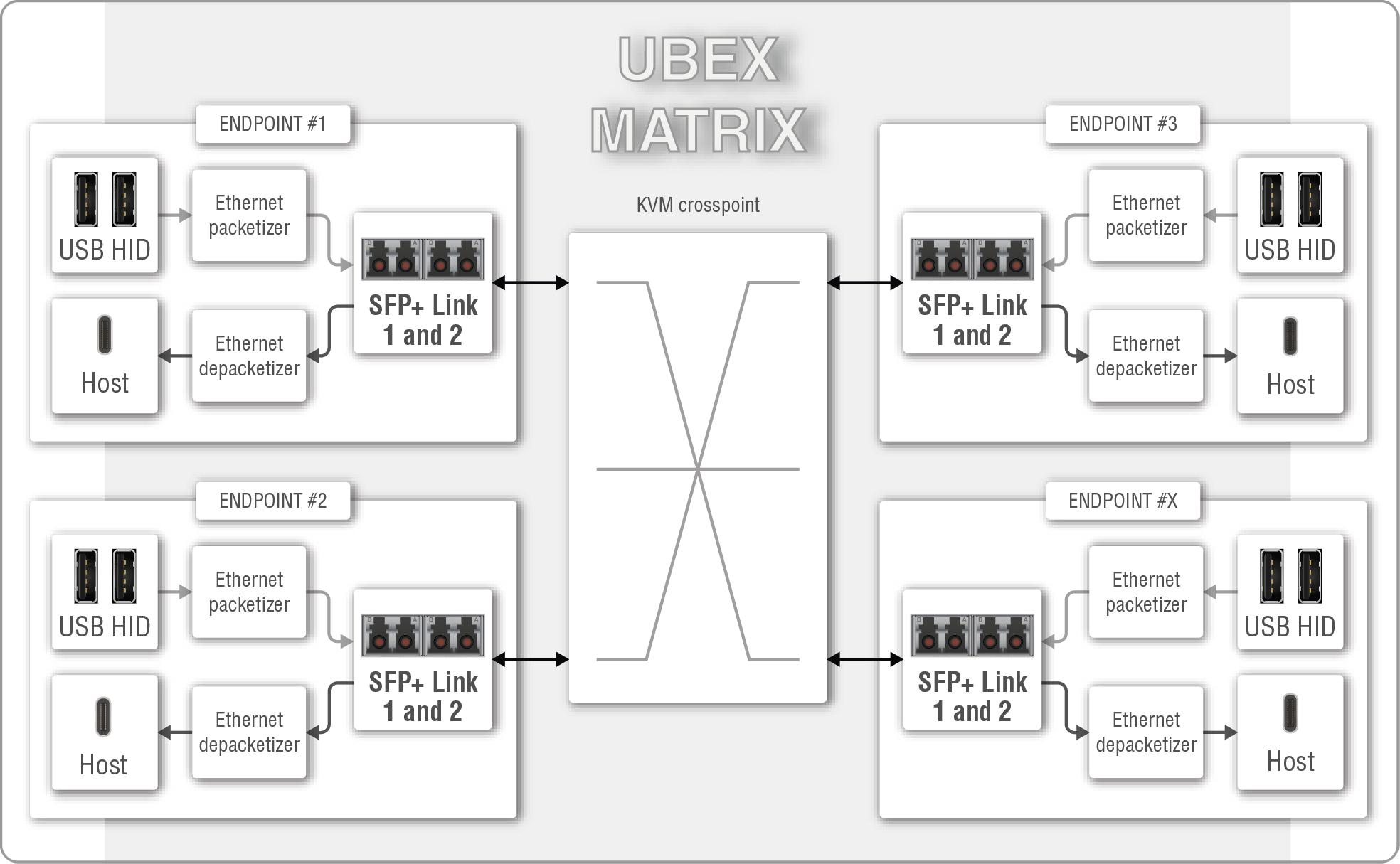
Port diagram of the USB K+M interface for the UBEX matrix
The Concept
All controller (keyboard & mouse) and controlled (PC, workstation, etc) devices can be connected to each other using the K+M crosspoint in the UBEX matrix. It is also possible to connect the controlled and the controller devices which are plugged into the same F120 or F121 endpoints.
The USB K+M function supports emulated (composite) mode only. It means in the practice the perfect usage of special keyboard/mouse buttons (e.g. multimedia keyboards and touchpads) are not guaranteed because of the limitation of the emulated mode technology. Lightware recommends usage of ordinary keyboards built up to 104/105 keys and ordinary mice.
ATTENTION!Webcameras and other high bandwidth demand devices are not supported by the USB ports.
INFO:F120 and F121 models allow to connect USB HUB to the USB-A (K+M) ports. It gives an opportunity to make more USB HID device connections. Please note that information about the connected USB HID devices cannot be read out by the extender via the USB HUB.
INFO:Both types of USB ports (USB-A and USB-B) are working in all endpoint operation modes (TX, RX and TRX) as well.
INFO:Point-to-point connections are supported only. No point-multipoint connections are allowed recently.
6.10.2. USB K+M Extension - Example
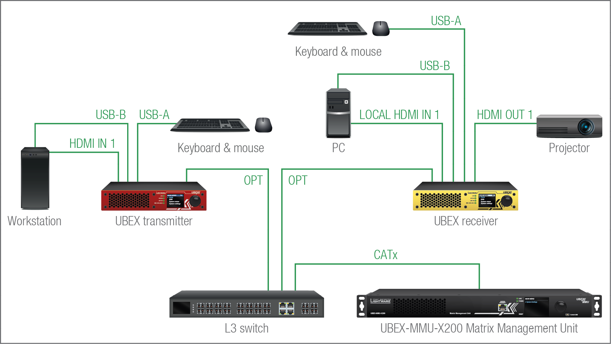
The Concept
Both endpoint devices in the UBEX matrix have controller (keyboard & mouse) and controlled (Workstation and PC) devices. All USB host and HID devices can be connected to each other using the K+M crosspoint.
The USB K+M properties and the crosspoint settings can be set using two methods:
▪Lightware Device Controller (LDC) / Built-in Website - see the details in the Crosspoint Menu - USB Layer section;
▪LW3 protocol commands - see the details in the USB K+M Settings (F120 / F121 Models) section.
6.11. USB KVM / USB 2.0 Interface (F130 Model)
DIFFERENCE:Only UBEX-PRO20-HDMI-F130 model is built with USB KVM and USB 2.0 feature.
6.11.1. Technical Background
Port Diagram
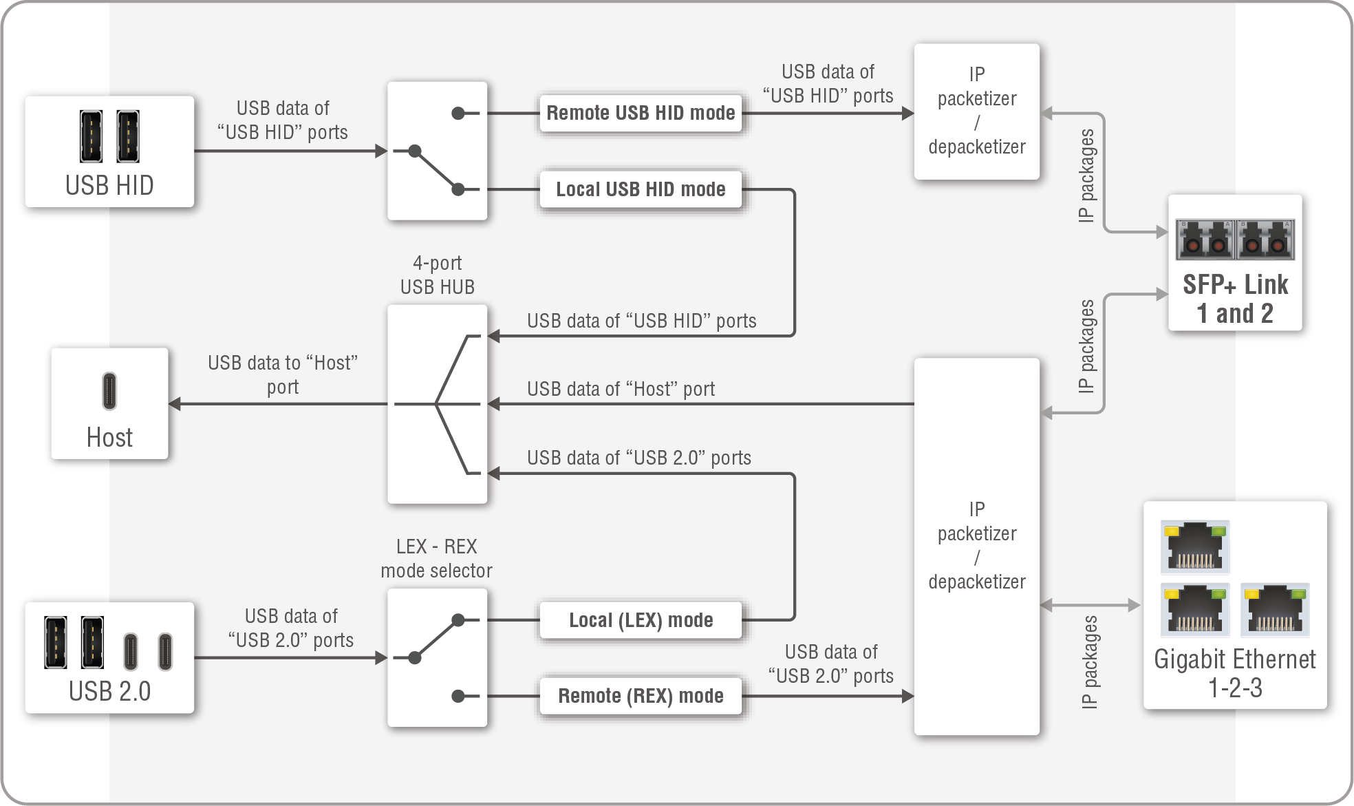
Port diagram of the USB KVM feature of the F130 model
Ports
UBEX-PRO20-HDMI-F130 model is built with a Host port (USB-C) for the host device (e.g. a computer), two USB HID ports (2x USB-A) for the HID devices (e.g. keyboard, mouse, presenter) and four USB 2.0 ports (2x USB-A; 2x USB-C) for the user's USB 2.0 devices (e.g. mass storage, web camera, microphone, etc).
ATTENTION!USB-C ports receive USB data only, no AV signal transmission is accepted. It supports USB 2.0 standard only.
Operation of USB HID Ports
There are two operation modes of the USB HID ports:
▪Local mode - the local host device (e.g. a computer) that is connected to the local Host port can be controlled by the local HID devices (e.g. keyboard, mouse, presenter).
▪Remote mode - the remote host device (e.g. a computer) that is connected to the remote Host port of the connected F130 extender can be controlled by the local HID devices (e.g. keyboard, mouse, presenter). The USB signal is transmitted over the SFP+ link 1 and 2 only.
The operation mode can be set using the following methods:
▪Lightware Device Controller (LDC) - see the details in the Crosspoint Menu - USB Layer section;
▪LW3 protocol commands - see the details in the Switching the Emulated Port to One Destination and the Switching the Local Emulated Port to the Local Destination sections.
Operation of USB 2.0 Ports
There are three operation modes of the USB 2.0 ports:
▪Local (LEX) mode - the ports are mounted on the connected local host device (e.g. a computer) via the local Host port. The ports appear as extended USB devices like a connected mass storage.
▪Remote (REX) mode - the ports are mounted on the connected remote host device (e.g. a computer) via SFP+ link 1 and 2 or the Gigabit Ethernet 1-2-3 ports.
▪Disabled mode - the USB 2.0 ports are disabled. In this mode there is no bandwidth reservation, see the attention section below.
ATTENTION!The USB KVM and the USB 2.0 transmission reserves 2 Gbps bandwith also in LEX and REX modes, so the the available total bandwidth is 8 Gbps in case of 1x10G SFP+ connection and 18 Gbps in case of 2x10G SFP+ connection. In case of disabled mode, this restriction is ceased and the available bandwidth is up to 20 Gbps. See more details about the bandwidth calculation for this model in the F130 Endpoint Model section.
INFO:In case of remote (REX) mode the compatible Icron USB devices can be discovered over the SFP+ link and over the Gigabit Ethernet links as well. The discovery interface can be changed by the user, see more details in the Setting the Icron Traffic Direction section. The connected devices can be UBEX extenders or any compatible third-party Icron device.
INFO:The Host USB-C port receives USB data only, no AV signal transmission is accepted. It supports USB 2.0 standard only.
The operation mode can be set using the following method:
▪LW3 protocol commands - see the details in the Setting the Operation Mode of the Icron USB 2.0 Module section.
INFO:The operation mode of the USB HID and USB 2.0 ports can be set separately.
6.11.2. Pairing the Icron Devices
There are two methods available for pairing or connecting a LEX through a crosspoint to one or multiple REX devices:
▪by using the Switchable USB protocol command - see the details in the Pairing to a Device section;
▪by using LARA (Lightware Automation Room Application) modules.
LARA Icron Module
The LARA Icron USB 2.0 module provides discovery and pairing of the Icron devices on the network. User interfaces for computers or touchscreens can be configured and personalized for the easy graphical access to the USB 2.0 features.
Crosspoint UI of a sample 2x2 Icron USB 2.0 matrix system
LARA is embedded into the firmware package of several Lightware product families:

|

|

|

|
|
|
See the detailed step-by-step descriptions about the configuration of the LARA Icron modules in the LARA user manual: https://go.lightware.com/lara-pum
Learn more about LARA in the dedicated homepage on the Lightware website:
https://www.lightware.com/en/products/Software/lara-software
6.11.3. USB KVM Extension - Example
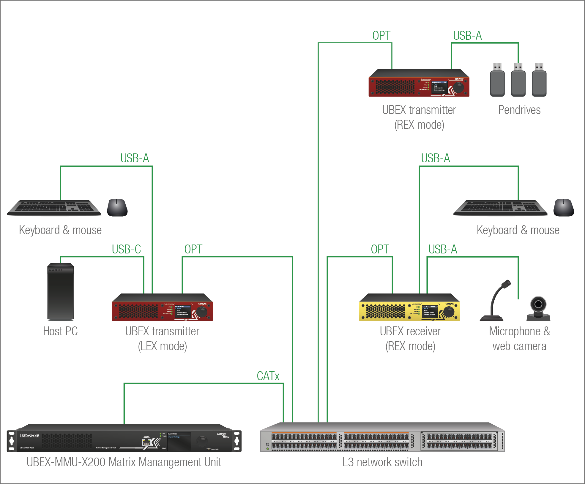
The Concept
The UBEX matrix contains two F130 transmitters and an F130 receiver. One TX is set as an Icron LEX (Local Extender) that connects to the host PC and a keyboard and a mouse for the local controlling. The other transmitter and the receiver are set as Icron REX (Remote Extender), which can be connected to the LEX over the SFP+ interface via the 10G network switch. The system is supervised by the UBEX-MMU-X200 matrix management unit.
The following USB devices are connected to the UBEX receiver:
▪a microphone and a webcamera on the USB 2.0 ports;
▪a keyboard and a mouse on the USB HID ports.
The following USB devices are connected to the UBEX transmitter (LEX mode):
▪a keyboard and a mouse on the USB HID ports.
When the receiver (REX) is paired with the transmitter (LEX), the host computer can be controlled over the remote keyboard and mouse and the USB signal of the webcamera/microphone can be received by the host computer.
The following USB devices are connected to the UBEX transmitter (REX mode):
▪three pendrives on the USB 2.0 ports.
When the receiver (REX) is paired with the transmitter (LEX), the host computer detects the remote pendrives as local USB devices.
The settings of the transmitter (LEX mode) are the following:
▪USB HID ports: Local mode
▪USB 2.0 ports: Local (LEX) mode
The settings of the transmitter (REX mode) are the following:
▪USB HID ports: Remote mode
▪USB 2.0 ports: Remote (REX) mode
The settings of the receiver (REX mode) are the following:
▪USB HID ports: Remote mode
▪USB 2.0 ports: Remote (REX) mode
Definitions
DEFINITION:SFP: the small form-factor pluggable (SFP) is a compact, hot-pluggable optical module transceiver used for both telecommunication and data communications applications. It is a popular industry format jointly developed and supported by many network component vendors. *
DEFINITION:SFP+: the enhanced small form-factor pluggable (SFP+) is an enhanced version of the SFP that supports data rates up to 10 Gbit/s. *
ATTENTION!The MMU accepts SFP modules only because of the hardware limitation of the SFP slot.
* Source: https://en.wikipedia.org/wiki/Small_form-factor_pluggable_transceiver
6.12.1. SFP+ Interface for the Endpoints
The endpoint devices are built with 2x 10 GbE SFP+ ports to transmit the video streams between the receiver and the transmitter.
The following methods can be applied to connect the endpoint devices to the network switch:
▪2x SFP+ transceiver module up to 10Gbps bandwidth/module. The modules can be singlemode or multimode, built with LC duplex connectors or BiDi modules; or SFP+ to RJ45 modules with copper solution. The maximum allowed fiber optical cable length depends on the installed SFP+ modules. Always check the specification of the module.
▪2x 10 GbE DAC cable
ATTENTION!Always apply equal length copper cables for both SFP+ to RJ45 modules in case of 20G signal transmission. Different cable lengths may cause data package loss. See more information about the appliable cable lengths and types in the Maximum Cable Extensions section.
INFO:The maximum available bandwidth with the endpoint device is 20 Gbps, which requires 2x 10 GbE SFP+ module or DAC cable to install. If one 10 GbE SFP+ module or DAC cable is installed only, but the signal is 4K@60 Hz (which requires 14 Gbps to transmit), the signal transmission will be disabled.
INFO:For more details of the installation steps of SFP+ modules and DAC cables, see the SFP / SFP+ Slot Connection section.
INFO:In case of SFP+ to RJ45 module installation, the endpoint device sets the cooling fans to (minimum) 2500 rpm automatically.
6.12.2. SFP Interface for the MMU
The UBEX-MMU-X200 matrix management unit has one 1 GbE SFP module slot for the fiber optical connection via the network switch.
The following methods can be applied to connect the MMU to the switch:
▪1x SFP transceiver module up to 1 Gbps bandwidth. The module can be singlemode or multimode, built with LC duplex connectors or BiDi modules. The maximum allowed fiber optical cable length depends on the installed SFP modules. Always check the specification of the module.
▪1x 1 GbE DAC cable
INFO:For more details of the installation steps of SFP modules see the SFP / SFP+ Slot Connection section.
6.13. Redundant 10G Link Channels
The UBEX F-series and R-series endpoint models are built with two equivalent 10 GbE Ethernet channels, which are based on a redundant operating principle. It means both 10 GbE Ethernet connections are able to take the place of the other one in case of a connection loss. For example, if one of the two SFP+ modules is pulled out during the operation, the AV transmission keeps going.
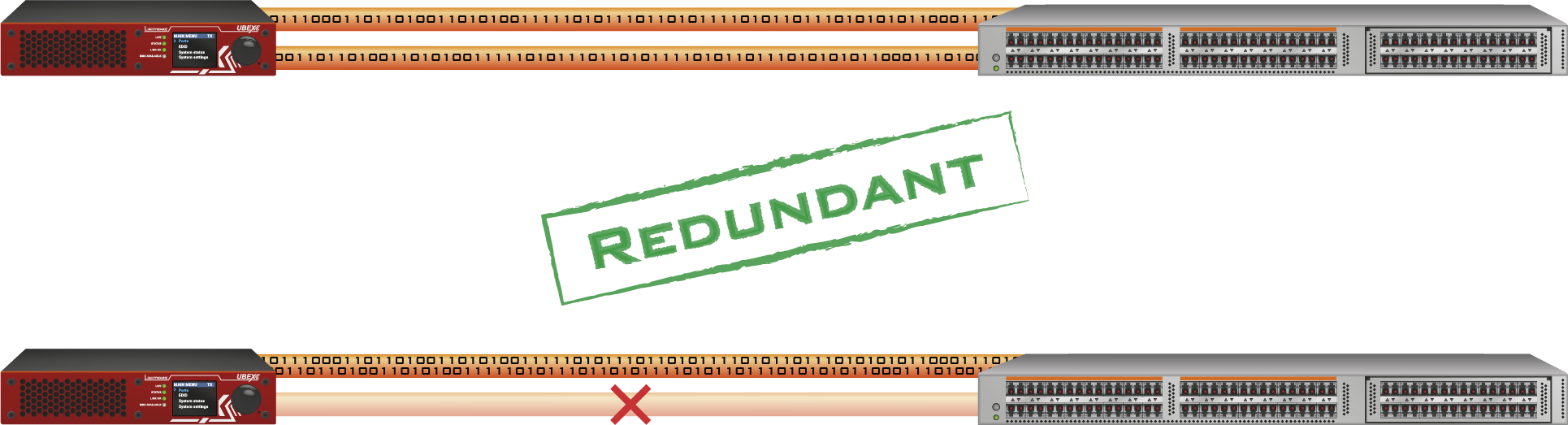
ATTENTION!The optical connection redundancy is available only in case of one or two HDMI signals where the sum of the required bandwidth is not greater than 10 Gb/s. Please check the Bandwidth Requirements of the Resolutions section for the details.
INFO:If two HDMI signals are transmitted where the sum of the bandwidth is greater than 10 Gb/s, there are limitations in the signal transmission on both the transmitter and the receiver side. See more details about it in the Bandwidth Limitation section.
INFO:Redundancy is available in case of fiber optical and copper (RJ45) connections as well.
6.14. Further Built-in Features
6.14.1. UBEX Matrix Database Backup and Restore
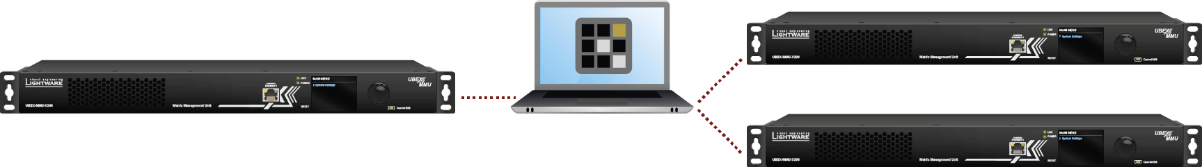
The UBEX matrix cloning is a simple method to save the database of the matrix and the configuration settings of the MMU to a backup file. This file can be saved to your computer and can be restored to the MMU later. See more information about the content of the backup file in the Content of Backup File section.
You can find more information about the backup procedure in the System Tab section.
6.14.2. Advanced EDID Management
Factory Preset EDIDs
The factory EDIDs (F1-F144) are factory preprogrammed and cannot be modified. These are the most common signal formats. They are specially provided to force the graphic cards to output only the exact pixel resolution and refresh rate.
Universal EDID allows multiple signal formats, including all common VESA defined resolutions. The use of universal EDID is recommended for fast and easy system setup.
Sources and Destinations
The EDID memory consists of four parts:
▪Factory EDID list shows the pre-programmed EDIDs (F1-F144).
▪Dynamic EDID list shows the sinks connected to the device's outputs (D). The unit stores the last display devices’ EDID on either output, so there is an EDID shown even if there is no display device attached to the output port at the moment.
▪User memory locations (U1 – U64) can be used to save custom EDIDs.
▪Emulated EDID list shows the currently emulated EDID for the inputs (E). The source column displays the memory location that the current EDID was routed from.
The source reads the EDID from the Emulated EDID memory on the INPUT port. Any EDID from any of the User/Factory/Dynamic EDID lists can be copied to the user memory.
There are two types of emulation: static and dynamic.
▪Static EDID emulation: an EDID from the Factory or User EDID list is selected. Thus, the Emulated EDID remains the same until the user emulates another EDID.
▪Dynamic EDID emulation: it can be enabled by selecting D EDID memory. The attached monitor’s EDID is copied to the input; if a new monitor is attached to the output, the emulated EDID changes automatically.
See more information about the settings in the EDID Management Menu section in the LDC software.
6.14.3. Centralized Firmware Update
The firmware update of the connected endpoint devices can be made and supervised by the MMU. You just need to select the updateable devices and one click only for the procedure starting. This method is the most easiest way to keep your UBEX matrix up to date and get the latest features.
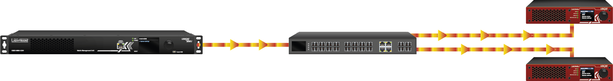
ATTENTION!The centralized firmware update feature is available from MMU firmware v1.1.0 and endpoint firmware v1.3.1.
See the details about this feature in the Endpoint Update - Centralized Firmware Update section.
6.15. Software Control Modes
User has more possibilities to control the device besides the front panel LCD screen. The following list contains the software control modes:
▪Lightware Device Controller (LDC) - you can connect to the UBEX matrix via our control software using Ethernet interface and control or configure the matrix as you wish. For the details see the Software Control - Lightware Device Controller chapter.
▪Built-in website of the MMU - you can connect to the UBEX matrix via a web browser application using Ethernet interface and control or configure the matrix as you wish. For the details, see the Software Control - Built-in Web chapter.
▪LW3 protocol commands: you can configure the matrix by using the full-range command set of LW3 protocol. For more details, see the Programmers Reference chapter.
7. Software Control - Built-in Web
The built-in website of the Matrix Management Unit allows to connect to and control the UBEX matrix via a web browser. The range of the controlling features are the same as in the case of Software Control - Lightware Device Controller.
System Requirements
Operating System: Microsoft Windows 10, Apple macOS, Linux.
Web Browser: Mozilla Firefox, Google Chrome, Apple Safari.
ATTENTION!The EDID export function works only in Windows and macOS operating systems under Mozilla Firefox or Google Chrome web browsers.
7.1. Establishing the Connection
ATTENTION!Please be sure that the computer is in the same network as the UBEX matrix. If the computer has multiple Ethernet connections (for example Wi-Fi and LAN connections are used simultaneously) you will need to know the IP address for the one that is used for controlling the MMU. #builtinweb #web
Step 1.Connect the matrix and the computer either via
▪Ethernet, with LAN patch cable, or
▪Ethernet, with LAN cross cable.
Step 2.Change to the desired IP settings if it needed.
Step 3.Type the IP address to the address bar of the web browser and press enter (the factory default address is 192.168.0.100).
7.2. The Layout of the Built-in Web
The built-in web page allows the same controlling functions which are available via the Lightware Device Controller. Select a menu item on the left side; the default screen is the Crosspoint menu. See the detailed control features in the Software Control - Lightware Device Controller chapter.
ATTENTION!Please enable the pop-up windows in your browser; certain contents are only displayed in a new window.

Built-in Web page displaying the Crosspoint menu
8. Software Control - Lightware Device Controller
The device can be controlled by a computer through Ethernet interface with the Lightware Device Controller (LDC). The software can be installed on a Windows PC or macOS. The application and the User Manual can be downloaded from www.lightware.com.
INFO:After the installation the Windows and the macOS application has the same look and functionality.
Minimum System Requirement
RAM: 1 GB
Minimum display resolution: 1280x720
Installation for Windows OS
Run the installer. If the User Account Control drops a pop-up message, click Yes.
During the installation you will be prompted to select the type of the installation: normal and the snapshot install:
|
Normal install |
Snapshot install |
|
Available for Windows and macOS |
Available for Windows |
|
The installer can update only this instance |
Cannot be updated |
|
Only one updateable instance can exist for all users |
More than one different version can be installed for all users |
Comparison of installation types
ATTENTION!Using the Normal install as the default choice is highly recommended.
Installation for macOS
Mount the DMG file by double clicking on it, and drag the LDC icon over the Applications icon to copy the program into the Applications folder. If you want to copy the LDC into another location just drag the icon over the desired folder.
ATTENTION!Please check the firewall settings on the macOS device. LDC needs to be added to the exeptions of the blocked software for the proper operation.
Updating of LDC
Step 1.Run the application.
The Device Discovery window appears automatically, and the program checks the available updates on Lightware’s website and opens the update window if LDC updates are found.
The current and the update version number can be seen at the top of the window, and they are shown in this window even with the snapshot install.
The Update window can also be opened by clicking on the About icon and the Update button.
Step 2.Set the desired update setting in the Options section.
▪If you do not want to check for the updates automatically, uncheck the circle that contains the green tick.
▪If you want to postpone the update, a reminder can be set with different delays from the drop down list.
▪If the proxy settings traverse the update process, set the proper values, then click on the OK button.
Step 3.Click on the Download update button to start the updating.
The updates can be checked manually by clicking on the Check now button.
8.2. Running the LDC
The common way to start the software is to double-click on the LDC icon. But the LDC can also be run by command line parameters as follows:
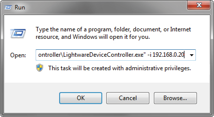
Launching of LDC in a Run window in Windows operating system
Connecting to a Device with Static IP Address
Format: LightwareDeviceController -i <IP_address>:<port>
Example: LightwareDeviceController -i 192.168.0.20:6107
The LDC is connected to a device with the indicated static IP address directly; the Device Discovery window is not displayed. When the port number is not set, the default port is used: 10001 (LW2 protocol - not supported by the UBEX extenders). For LW3 devices, use the 6107 port number.
Adjusting the Zoom
The window can be zoomed to a specific value to fit to the resolution of the desktop (higher/lower). '1' is the default value (100%).
Format: LightwareDeviceController -z <magnifying_value>
Example: LightwareDeviceController -z 1.2
ATTENTION!The last set value is stored and applied when LDC is started without a parameter.
Step 1.Connect the device to a computer via the following methods:
▪Ethernet - in the case of the MMU, the network switch, or any endpoint device;
▪RS-232 - in the case of the MMU only.
Step 2.Run the controller software; device discovery window appears automatically.
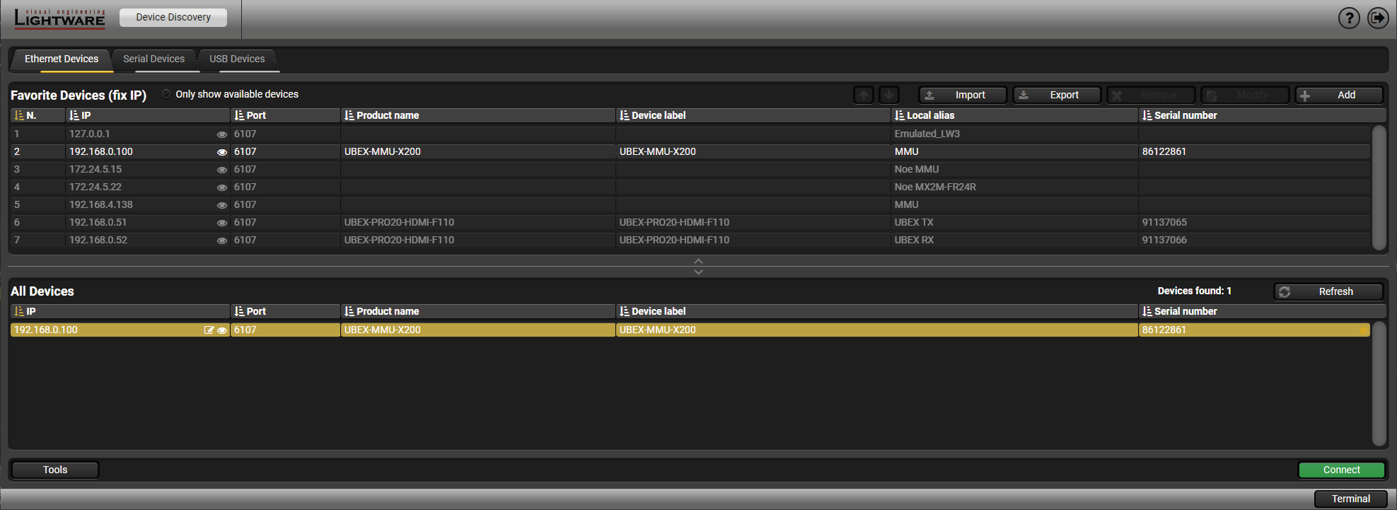
Device discovery window in LDC
Change IP Address
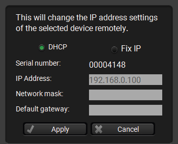
To modify IP address settings quickly, it is not necessary to enter the device's settings/network menu, you can set them by clicking on the pencil icon next to the IP address. #network #ipaddress #dhcp
You can see the new settings only in this window.
Import/Export the List of Favorite Devices
DIFFERENCE:This feature is available only from LDC version v2.5.5.
The list of favorite devices can be exported/imported using the dedicated buttons (saved as *.JSON file). The list can be imported later (in another computer, too), but please note that the current list will be overwritten by the imported list.
Step 3.Select the UBEX-MMU-X200 device from the discovered Ethernet devices or Serial devices; when the device is connected through RS-232 click on the Query button next to the desired serial port to display the name of the device and the serial number. Double click on the device name or select the device and click on the green Connect button.
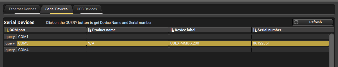
Serial devices tab
Favorite Devices (fix IP)
By clicking on the grey star icon Aside from the discovered devices, the most used units can be saved to the Favorite devices.
ATTENTION!The devices set with static (fix) IP address only can be saved as favorite device.
Once the device is set as favorite, the star icon will be highlighted with yellow and the device will be displayed between the Favorite Devices (fix IP) window section.
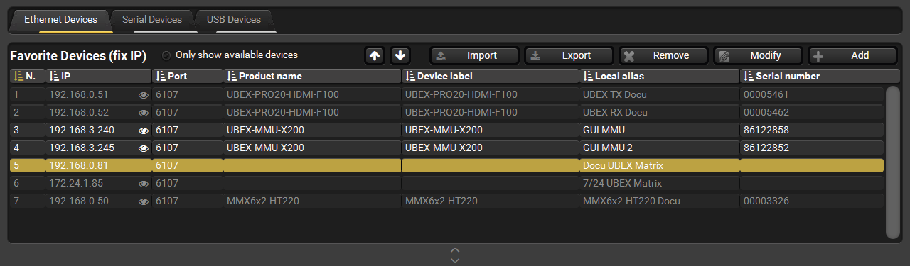
Favorite Devices window section
8.4. Crosspoint Menu - Video Layer
8.4.1. Grid View
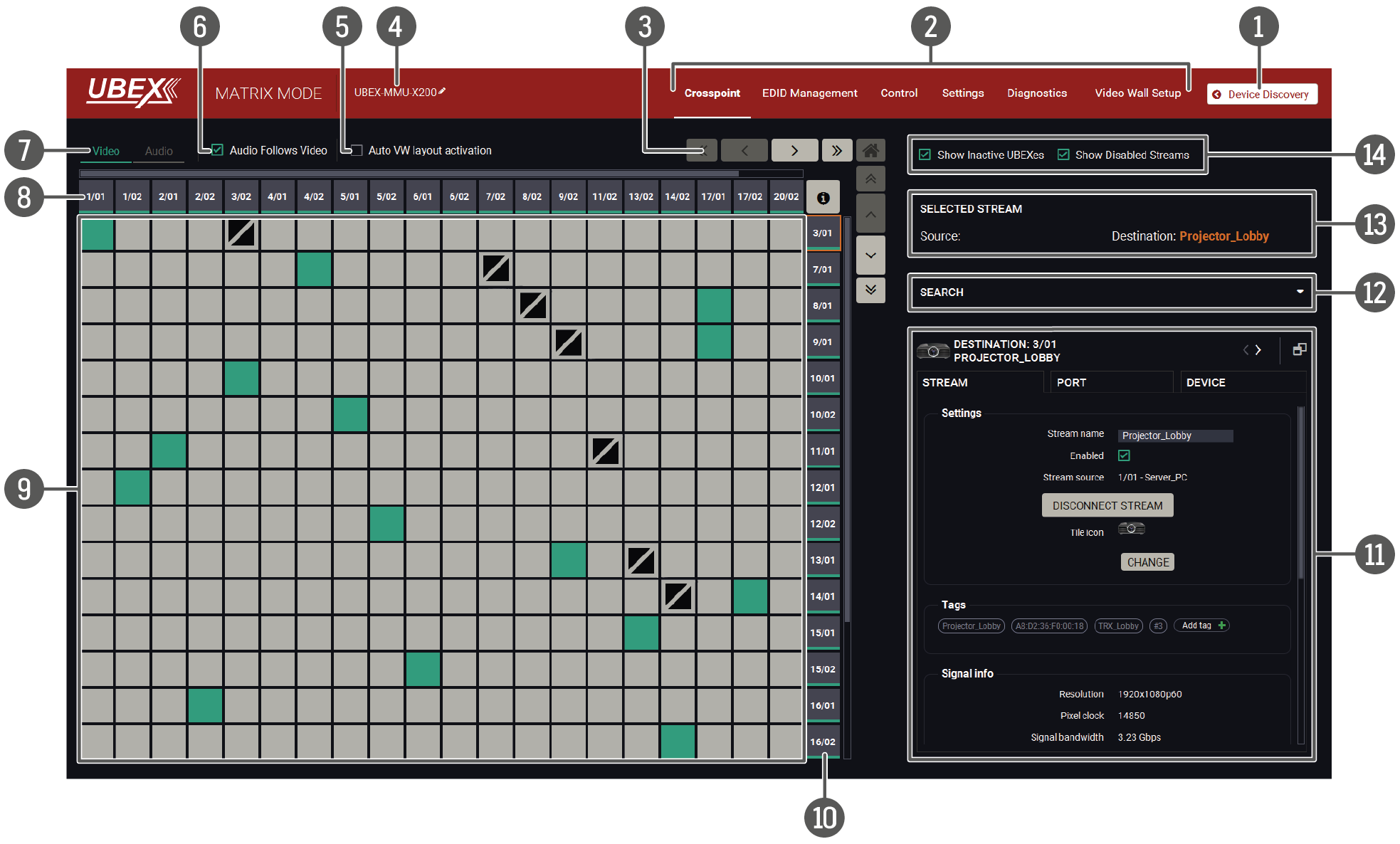
The grid view of the crosspoint menu - Video layer in Matrix mode
The Concept
The Crosspoint menu displays the UBEX matrix in grid layout with all sources (the input ports of the transmitters / transceivers) and destinations (the output ports of the receivers / transceivers). Clicking on a source or destination panel, the properties and settings of the selected item appear on the right side. Clicking on the icon, the properties section opens in new window. The selected source/destination and crosspoint are framed with orange. #switch #crosspoint #gridview
Legend of the Crosspoint Menu
|
|
Device Discovery |
Clicking on the button results in returning to the Device Discovery window. The connection with the current device will be terminated. |
|
|
|
Main menu |
The available menu items (Crosspoint Menu - Video Layer, EDID Management Menu, Control Menu, Settings menu, and Video Wall Setup) are displayed. The crosspoint can be displayed in Grid view and Tile view. The Device Map, MMU Settings, and the Terminal Window are available under the Settings menu. |
|
|
|
Navigation buttons |
Clicking on the navigation buttons shows the available sources/destinations and crosspoints which cannot be displayed within the recent window size. The |
|
|
|
Device label of the MMU |
The device label of the MMU is displayed here. It can be modified by the user to any unique name by clicking on the icon. The device label can be 39 characters long and ASCII characters are allowed. Longer names will be truncated. |
|
|
|
Auto VW layout activation switcher |
Auto Video Wall layout activation switcher, see the details in the Crosspoint Menu with Video Wall section. |
|
|
|
Audio follows video switcher |
The explanation of the two available options is the following: ▪Enabled: the audio stream follows the video stream when the video crosspoint is changed. Aside from this the audio streams can be switched separately from the video streams on the Audio crosspoint tab. ▪Disabled: switching of a video stream does not affect the audio crosspoint state. |
|
|
|
Layer tabs |
The video and the audio crosspoint panel can be selected on the tabs. |
|
|
|
Source streams |
Each tile represents a stream coming from one of the input ports of the transmitter or transceiver. See the explanation of the source numbering in the Source and Destination Numbering section. |
|
|
|
Connections |
The crosspoint connections can be selected in this table. |
|

|
The tile means a denied connection (only for transceivers). The explanation is the input port of the transceiver cannot be selected to the output port of the same transceiver. |
||
|
|
Destination streams |
Each tile represents an output port of a receiver or transceiver. See the explanation of the destination numbering in the Source and Destination Numbering section. |
|
|
|
Properties window |
The properties, available settings, and status information of the selected source or destination are displayed in this section. Three tabs are available: Stream, Port, and Device. Clicking on the icon, the properties section opens in a new window. See more details about the source ports in the Video Source Port Properties Window section and about the destination ports in the Video Destination Port Properties Window section. |
|
|
|
Search field |
Streams, ports, and devices can be searched in the field. See the details in the Search Field section. |
|
|
|
Selected / Highlighted streams |
Showing the currently selected connections. Move the cursor above the desired crosspoint and the names of the source and destination are displayed in the field. |
|
|
|
Show Inactive UBEXes / Disabled Streams switchers |
When they are enabled, the inactive devices / disabled streams are shown in the crosspoint table. When they are disabled, the inactive devices / disabled streams are hidden. |
|


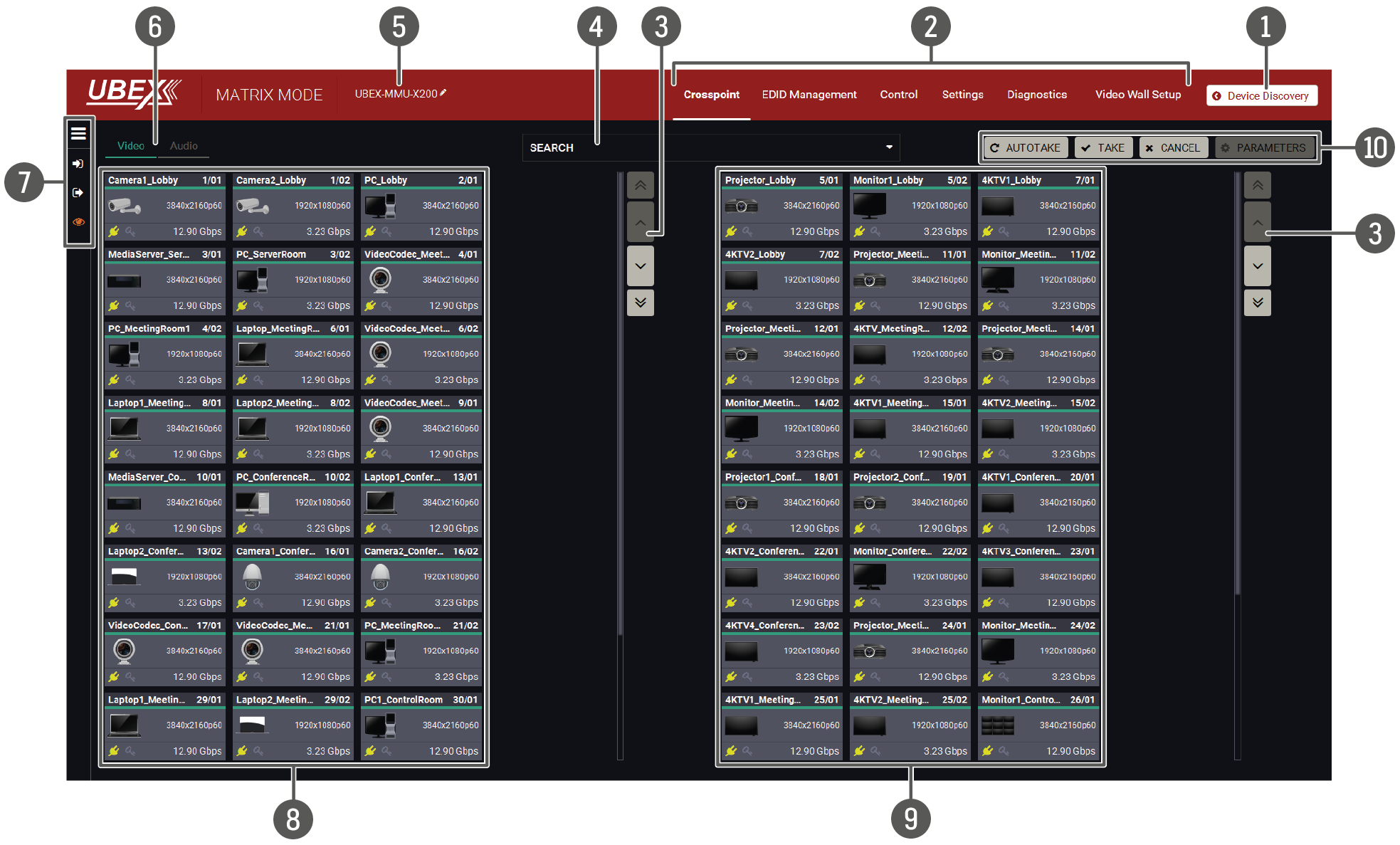
The tile view of the crosspoint menu - Video layer in Matrix mode
The Concept
The tile view of the UBEX matrix is suitable to review the entire AV system with the details as well. The tiles represent input or output ports and additionally show the most important port and signal information. Thus, the user can check the status of many ports at the same time. #tileview
Legend of the Crosspoint Menu
|
|
Device Discovery |
Clicking on the button results in returning to the Device Discovery window. The connection with the current device will be terminated. |
|
|
|
Main menu |
The available menu items (Crosspoint Menu - Video Layer, EDID Management Menu, Control Menu, Settings menu, and Video Wall Setup) are displayed. The crosspoint can be displayed in Grid view and Tile view. The Device Map, MMU Settings and the Terminal Window are available under the Settings menu. |
|
|
|
Navigation buttons |
Clicking on the navigation buttons shows the available sources/destinations and crosspoints which cannot be displayed within the recent window size. |
|
|
|
Search field |
Streams, ports, and devices can be searched in the field. See the details in the Search Field section. |
|
|
|
Device label of the MMU |
The device label of the MMU is displayed here. It can be modified by the user to any unique name by clicking on the icon. The device label can be 39 characters long and ASCII characters are allowed. Longer names will be truncated. |
|
|
|
Layer tabs |
The video and the audio crosspoint panel can be selected on the tabs. |
|
|
|
Connections menu |
The meanings of the icons are the following: |
|
|
|
Connections menu button: Clicking on the icon expands the connection menu. See the detailed setting descriptions in the Connections Menu section on the next page. |
||
|
|
Input switch mode: The mode can also be named as Input priority-mode: an input port has to be selected at first then the connected output ports are shown. Thus, the output ports connected to the input port can be changed. |
||
|
|
Output switch mode: This mode can also be named as Output priority-mode: an output port has to be selected at first then connected input port is shown. Thus, the output port connected to the input port can be changed. |
||
|
|
View mode: This mode was designed to display the crosspoint state of a selected and its connected port(s). Crosspoint settings cannot be changed in View mode but port settings are available. |
||
|
|
Source streams |
Each tile represents a stream coming from one of the input ports of the transmitter or transceiver. See the explanation of the source numbering in the Source and Destination Numbering section. |
|
|
|
Destination streams |
Each tile represents an output port of a receiver or transceiver. See the explanation of the destination numbering in the Source and Destination Numbering section. |
|
|
|
Action buttons |
Action buttons: ▪Take - Autotake - Cancel buttons: selecting between the two input/output switching modes: the Take Mode and Autotake Mode. ▪Parameters button: clicking on the button opens the properties window of the selected source or destination. See more details about the source ports in the Video Source Port Properties Window section and about the destination ports in the Video Destination Port Properties Window section. |
|
Port Tiles
The port tiles and the colors of the displayed icons represent different states and information.
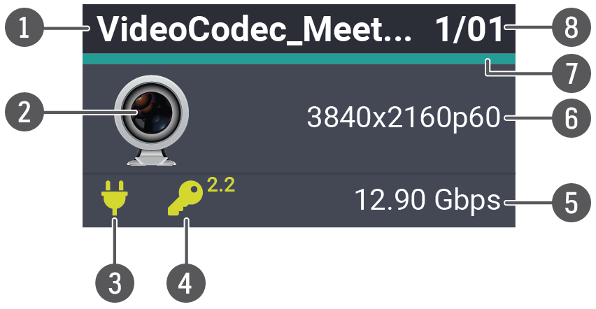
|
|
Port name |
||
|
|
Tile icon The icon can be changed under the Source/Destination properties window - Stream information section (it is available by clicking on the Parameters button). |
||
|
|
Hotplug state |
||

|
Source/sink is connected. |
||

|
Source/sink is not connected. |
||
|
4 |
HDCP state |
||

|
The signal is encrypted with HDCP 2.2. |
||

|
The signal is encrypted with HDCP 1.4. |
||

|
The sink device is not compatible with the current HDCP version. |
||

|
Signal is not HDCP-encrypted. |
||
|
5 |
Bandwidth of the stream |
||
|
6 |
Resolution / refresh rate of the stream |
||
|
7 |
Signal present indicator If turquoise, signal is present, if grey, signal is not present. |
||
|
8 |
Logical Device ID / Input/output port number |
||

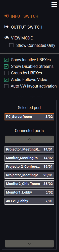
Clicking on the icon expands the Connections menu and more options and settings become available.
Switch Modes
▪Input Switch
▪Output Switch
▪View Mode
=Show Connected Only: when a source or destination stream is selected, only the connected streams are displayed on the other panel.
Display Modes
▪Show Inactive UBEXes: when enabled, the inactive devices are shown in the crosspoint table. When it is disabled, the inactive devices are hidden.
▪Show Disabled Streams: when enabled, the disabled streams are shown in the crosspoint table. When it is disabled, the disabled streams are hidden.
▪Group by UBEXes: the streams belong to one endpoint device are framed with white.
▪Audio Follows Video: The explanation of the two available options are the following:
=Enabled: the audio stream follows the video stream when the video crosspoint is changed. Aside from this the audio streams can be switched separately from the video streams on the Audio crosspoint tab.
=Disabled: switching of a video stream does not effect the audio crosspoint state.
▪Auto VW layout activation: the explanation of the two available options are the following:
=Enabled: the video wall layout becomes active suddenly when the crosspoint setting is changed in it.
=Disabled: switching of a source stream does not effect the video wall layout activation.
Connections
▪Selected Port: the currently selected source or destination stream.
▪Connected Ports: the streams are listed which are connected to the selected source or destination stream.
Switching Operations

If the Autotake button is grey colored the Take mode is active. In Take mode any crosspoint change – connecting/disconnecting ports to/from the previously selected port – is executed only after pressing the Take button. Following steps describe the process of the switching:
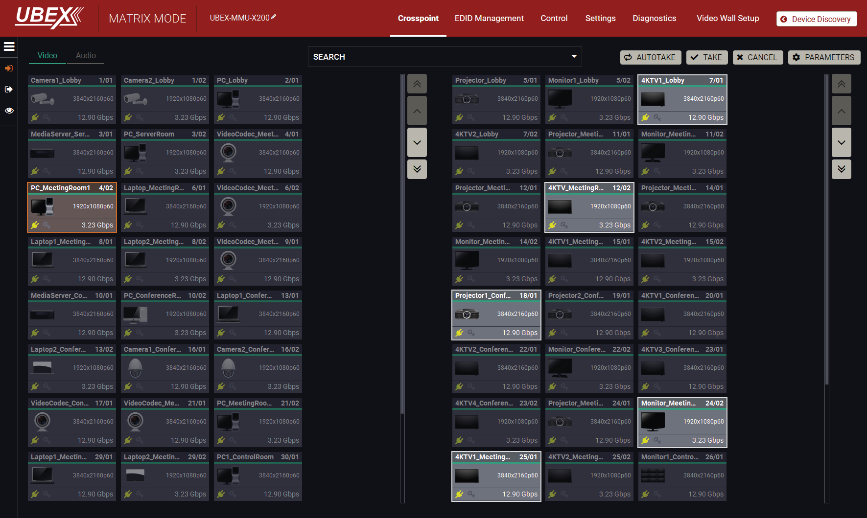
Input switching in Take mode
Step 1.Press the desired Input switch or Output switch button to select the switching mode.
Step 2.Select the desired port; it will be highlighted with orange color and displayed also in the Selected port section on the left.
Step 3.Connected ports are highlighted with white color and displayed also in the Connected ports section on the left.
Step 4.Create the desired crosspoint settings by selecting/deselecting the ports; they will start to blink.
Step 5.Press the Take button to execute changes or Cancel to discard.
INFO:Take mode remains active until it is switched off. Selecting another view mode or menu item does not effect the Take/Autotake mode state.
#switch #crosspoint

If the Autotake button is yellow colored, the Autotake mode is active. In this mode, any crosspoint change – connecting/disconnecting ports to/from the previously selected port – is executed immediately after pressing the port button. Following steps describe the process of the switching:
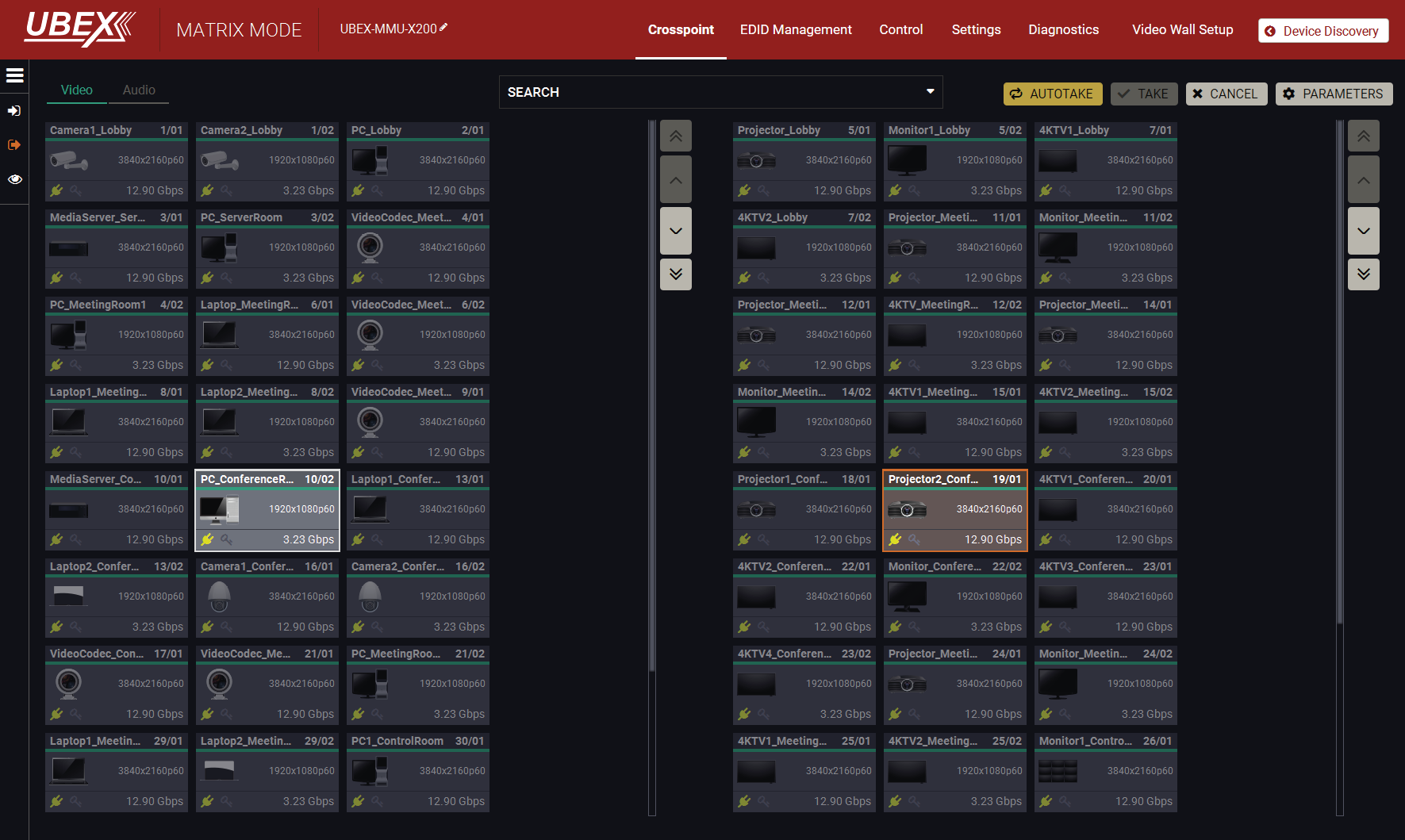
Output switching in Autotake mode
Step 1.Press the desired Input switch or Output switch button to select switching mode.
Step 2.Select the desired port; it will be highlighted with orange color and displayed also in the Selected port section on the left.
Step 3.Connected ports are highlighted with white color and displayed also in the Connected ports section on the left.
Step 4.Create the desired crosspoint settings by selecting/deselecting the ports; the changes are executed immediately.
INFO:Autotake mode remains active until it is switched off. Selecting another view mode or menu item does not effect the Take/Autotake mode state.
8.5. Crosspoint Menu - Audio Layer
DIFFERENCE:HBR audio formats are supported from LDC version v2.5.8b2, endpoint firmware version v2.0.0 and MMU firmware version v1.4.0 only. If the embedded audio signal is HBR and an HBR audio not supported error message received during the new crosspoint setting, please update the control software to the latest one. See more information about the updating procedure in the Install and Update section.
8.5.1. Grid View
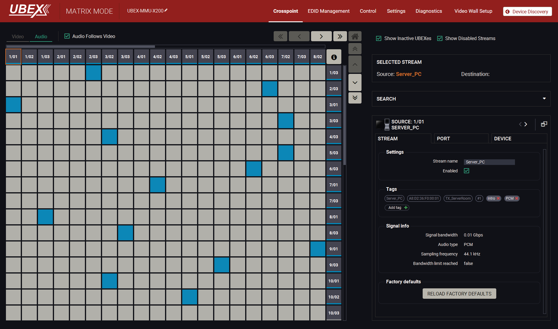
The grid view of the crosspoint menu - Audio layer in Matrix mode
The operation of the Audio layer in grid view is basically the same as the Crosspoint Menu - Video Layer.
Clicking on the source or the destination port the properties panel opens on the right side - all audio related information and options are available here. Tags are also attached to the audio stream. See the details about the available settings in the Audio Port Properties Windows section. #audio #switch #crosspoint
INFO:When the Audio follows video setting is enabled, the tags which are added to the video stream will be copied to the audio stream as well.
Two options are available switching the audio crosspoint settings:
▪Audio follows video: when the Audio follows video setting is enabled, the audio stream follows the video stream when the video crosspoint is changed. Aside from this the audio streams can be switched separately from the video streams on the Audio crosspoint tab.
▪Free audio crosspoint settings: when the Audio follows video setting is disabled, switching of a video stream does not effect the audio crosspoint state.
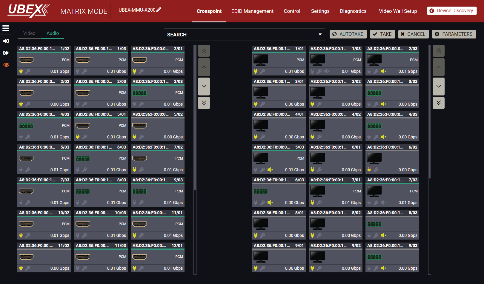
The tile view of the crosspoint menu - Audio layer in Matrix mode
Source and destination port properties are available by clicking on the Parameters button. Switching between the inputs and outputs has two available options: the Take Mode and Autotake Mode, the working methods are the same like in the Tile View of the Video layer.
Clicking on the Parameters button opens the properties of the selected source or destination stream. See the details about the available settings in the Audio Port Properties Windows section.
8.6. Crosspoint Menu - USB Layer
DIFFERENCE:Only UBEX-PRO20-HDMI-F120 and -F121 endpoint models are built with USB K+M ports and Only UBEX-PRO20-HDMI-F130 endpoint model is built with USB KVM ports. #km #usbkm #kvm #usbkvm #icron
8.6.1. Grid View
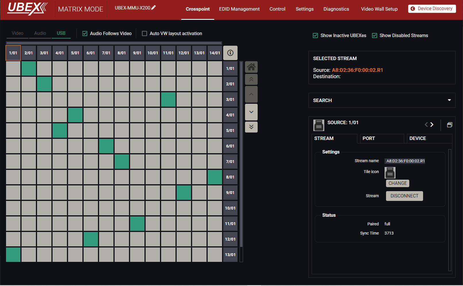
The grid view of the crosspoint menu - USB layer in Matrix mode
The operation of the USB layer in grid view is basically the same as the Crosspoint Menu - Video Layer.
Clicking on the source or the destination port the properties panel opens on the right side - all USB K+M related information and options are available here.
ATTENTION!In case of F130 model the control mode sets the operation mode of the USB HID ports only. GUI support of the USB 2.0 ports will be added in a future LDC software update.
INFO:Local control is also possible which means the controlled and the controller devices are plugged into the same F120 endpoint. For example, user can switch 1/01 source to 1/01 destination for the local USB K+M control.
INFO:Point-to-point connections are supported only. No point-multipoint connections are allowed recently.
8.6.2. Tile View
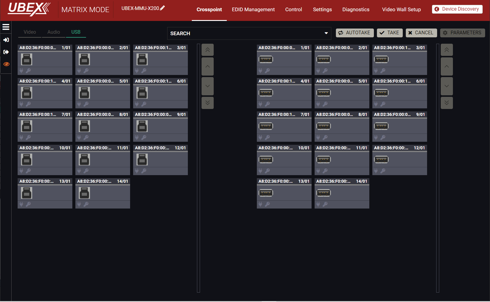
The tile view of the crosspoint menu - USB layer in Matrix mode
Source and destination port properties are available by clicking on the Parameters button. Switching between the inputs and outputs has two available options: the Take Mode and Autotake Mode, the working methods are the same like in the Tile View of the Video layer.
Clicking on the Parameters button opens the properties of the selected source or destination stream.
8.7.1. The Concept
The Search feature helps to customize the list of the endpoint devices in the UBEX matrix. If you want to find a stream or a source / destination device, do the following steps: #search #find
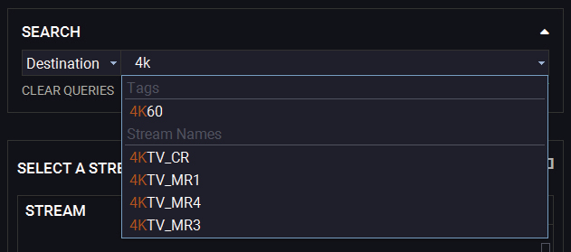
Step 1.Select the type of your search in the list: Source / Destination / Both.
INFO:The Both category means searching the words which are tagged to a Source and a Destination also.
Step 2.Type the name of stream or device. The hints will be appeared in the list.
The Search field
Step 3.Select the desired tag / stream name / device name. The crosspoint table will be filtered to the ports containing the searched text.
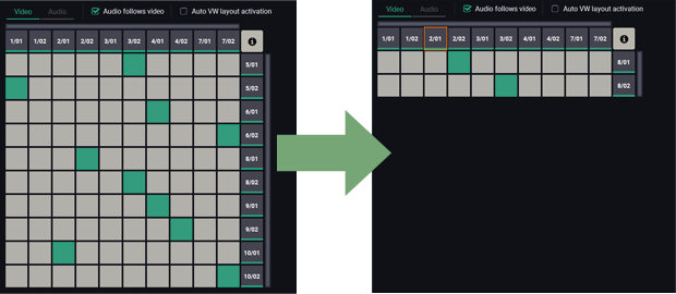
The crosspoint view before and after the search
Step 4.More key words can be added to the query for the best search efficiency. The query can be saved with the Add This Query button.

The Search field with more keywords
ATTENTION!The saved queries will be cleared after closing the LDC application.
8.7.2. Application Areas of the Search Field
The Search field is available where the streams and ports can get unique name and tags can be attached to them. These are:
▪Video crosspoint - Grid view / Tile view
=Video streams
=Video ports
=Endpoint Devices
▪Audio crosspoint - Grid view / Tile view
=Audio streams
=Audio ports
=Endpoint Devices
▪Control menu - Ethernet
=Ethernet ports
=Endpoint devices
▪Control menu - RS-232
=RS-232 ports
=Endpoint devices
INFO:The search field can be used for searching in the selected layer only. For example searching in the video crosspoint menu will not find the RS-232 ports.
8.8. Default Naming / Numbering Explanation
The following section explains the default numbering of the sources/destinations and the default stream names of the endpoint devices.
8.8.1. Source and Destination Numbering
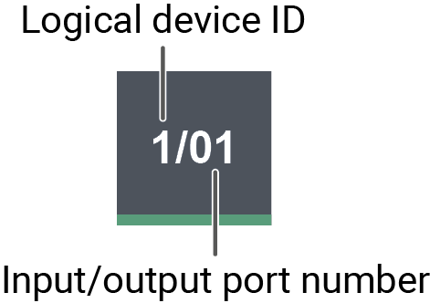
The source and destination ID contains two numbers: the logical device ID (it can be changed by the user) and the port number (it is fixed).
Logical device ID: It is created by the MMU based on the discovery order of the endpoints - independently of the operation mode. The first discovered endpoint gets the 1, the second one gets the 2, and so on.
INFO:The logical device ID can be reconfigured by the Device map feature. See the details in the Device Map section.
Input/output port number:
▪Transmitter (source): the stream of HDMI in 1 port is the 01, the stream of HDMI in 2 port is the 02;
▪Receiver (destination): the HDMI out 1 port is the 01, the HDMI out 2 port is the 02.
▪Transceiver (source and destination): the stream of HDMI in 2 port is the 02 on the source side, the HDMI out 1 port is the 01 on the destination side.
8.8.2. Default Naming of the Devices and the Streams
Device Name

The default name (label) of the device is the MAC address. It can be changed freely in the Device label field by the user.
Stream Name

The default name of the stream is calculated from the MAC address and the port number of the endpoint device where the stream is transmitted from. The MAC address and the port number is separated by a dot character.
Example: A8:D2:36:F0:00:33.S1
The green characters are the MAC address of the device, the red characters are the input port number. The stream name can be changed freely in the Stream name field by the user.
8.9. Video Source Port Properties Window
Clicking on a source port the properties panel opens on the right side. Clicking on the icon the properties section opens in new window.
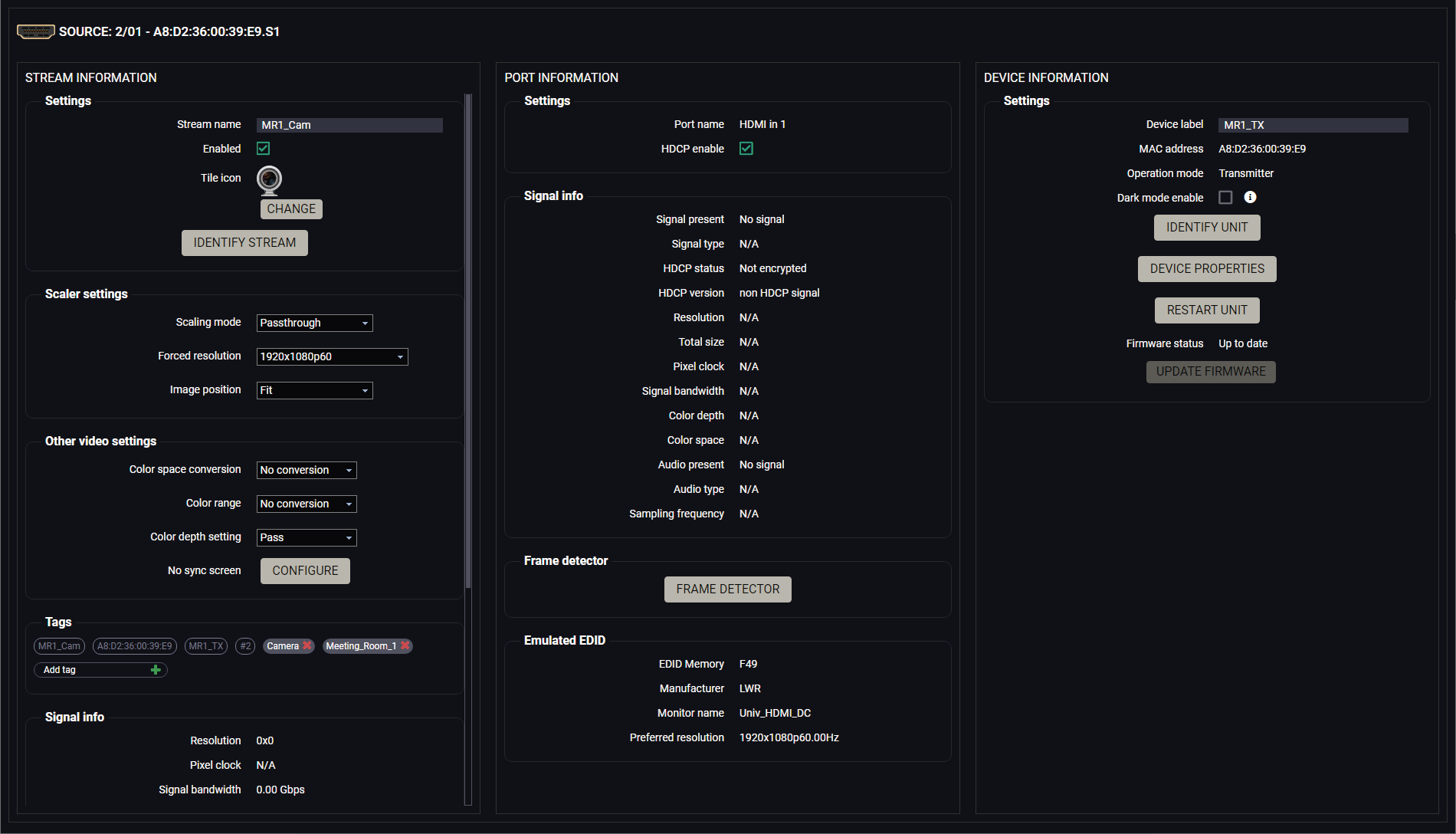
Video source port properties window
The most important information and settings of the stream are available in the Stream information section.
Settings
▪Stream naming;
▪Enabled: when it is checked in, the stream is enabled; if it is not, the stream is muted.
▪Tile icon: choose an icon which is the most suitable with the source/destination device connected to the endpoint.
▪Identify Stream / Identify Display. #identifystream #identifydisplay
Scaler / Frame Rate Converter Settings
▪Scaling mode / Output resolution mode: #scaler #frc
=Passthrough: the scaler is in pass-through mode.
=Forced resolution: the scaling is active, the selected value in the forced resolution option will be applied to the video signal;
▪Forced resolution: list of the available resolutions with refresh rate values. The selected one will be applied to the video signal. See the available resolutions in the Resolutions of the Scaler section.
▪Image position (Stretch / Fit / Center)
DIFFERENCE:The transceiver is built with scaler function on HDMI input 2 port from firmware version v2.1.0. The Image position setting on this port is a read-only parameter and fixed as Center in case of previous firmware versions.
DIFFERENCE:The tranmitter is built with scaler function on HDMI input 2 port from firmware version v2.4.1. The Image position setting on this port is a read-only parameter and fixed as Center in case of previous firmware versions.
▪Color space conversion (No conversion / RGB / YCbCr 4:4:4 / YCbCr 4:2:2) #csc #colorspace
▪Color range (No conversion / Full range / Limited range); #colorrange
▪Color depth setting (Pass / 8bpc / 10 bpc / 12 bpc) #colordepth
▪No Sync Screen (Test Pattern). #testpattern #nosyncscreen
Tags
Unique and configurable tags can be attached to the stream for the best identification. The tags are searchable in the Search Field. #tag
Signal Info
All important information (resolution, pixel clock, color space, e.g.) are available in the signal info section. The signal bandwidth and the bandwidth limit reached indicators can also be checked in this panel.
Related Audio Info
Information (presence, audio type, sampling frequency) of the embedded audio is available in the related audio info section.
Tools
▪Frame Detector - The tool displays the frame information of the current stream after a possible rescaling / frame rate conversion.
The most important information and settings of the input port are available in the Port information section.
Settings
▪HDCP setting (Enable / Disable) #hdcp
Signal Info
All important audio and video information (e.g. HDCP status, resolution, total size, pixel clock, color space, embedded audio information, e.g.) are available in the signal info section.
Emulated EDID
EDID-related information is displayed in the section.
Tools
▪Frame Detector - The tool displays the frame information of the original stream coming from the input port before a possible rescaling / frame rate conversion.
The most important information and settings of the transmitter are available in the Device information section.
Settings
▪Device label: the default label is the MAC address of the device but it can be changed to any unique name. #label #devicelabel
▪MAC address;
▪Operation mode: showing the current operation mode, it can be transmitter, receiver or transceiver. The operation mode can be changed in the Device Map.
▪Dark mode: the dark mode feature can be enabled or disabled. It keeps the LCD screen and the LEDs unlit to hide the device during an event when the settings is enabled. #darkmode
▪Identify unit: Clicking on the button makes the four front panel LEDs blink in green for 10 seconds. The feature helps to identify the device itself in the rack shelf or on the desk. #identifyme
▪Device properties: Clicking on the button opens the properties windows of the endpoint device. See the details:
=For Transmitter (TX) operation mode in the Transmitter Operation Mode section.
=For Transceiver (TRX) operation mode in the Transceiver Operation Mode section.
▪Restart unit: clicking on the button makes rebooting the device (the same as disconnecting from the power source and reconnecting again). #reboot #restart
▪Update firmware: clicking on the button makes launching the firmware update of the endpoint device by the MMU. See more details about it in the Endpoint Update - Centralized Firmware Update section.
8.10. Video Destination Port Properties Window
Clicking on a destination port the properties panel opens on the right side. Clicking on the icon the properties section opens in new window.
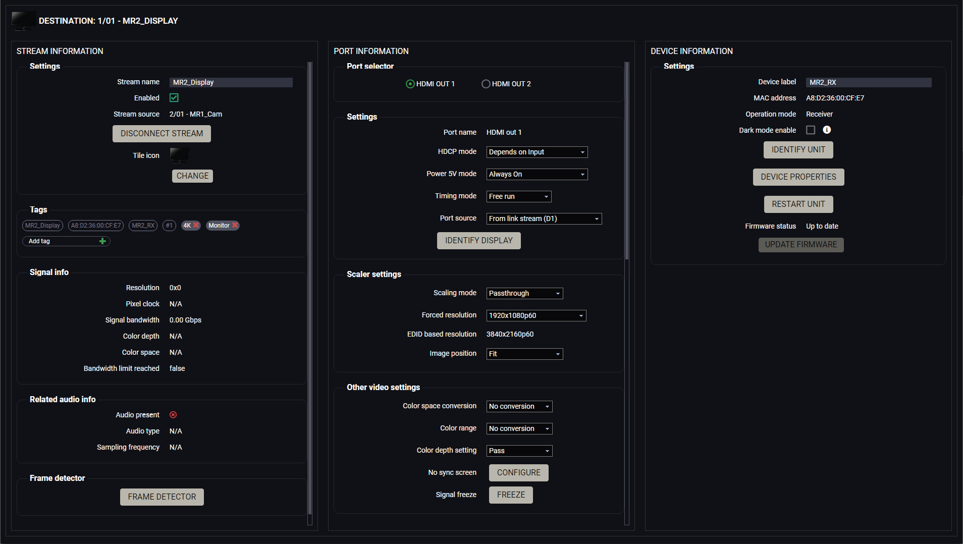
Video destination port properties window
The most important information and settings of the stream are available in the Stream information section.
Settings
▪Stream naming;
▪Enabled: when it is checked in, the stream is transmitted to the receiver; if it is not, the stream is muted.
▪Stream source: information about the currently connected stream and the ID of the source device.
▪Disconnect stream: clicking on the button results the source stream is disconnected from the output port.
▪Tile icon: choose an icon which is the most suitable with the source/destination device connected to the endpoint. #streamenable #disconnect
Tags
Unique and configurable tags can be attached to the stream for the best identification. The tags are searchable in the Search Field. #tag
Signal Info
All important information (resolution, pixel clock, color space, e.g.) are available in the signal info section. The signal bandwidth and the bandwidth limitation indicator are also can be checked in this panel.
Related Audio Info
Information (presence, audio type, sampling frequency) of the embedded audio is available in the related audio info section.
Tools
▪Frame Detector - The tool displays the frame information of the original stream coming from the connected source stream before a possible rescaling / frame rate conversion.
The most important information and settings of the input port are available in the Port information section.
Port Selector
INFO:The port selector menu is available for receiver operation mode only.
The two output ports which belong to the same endpoint device can be selected in the Port selector menu.
Because of the Source MUX settings it may happen that the selected destination stream is connected to none of the output ports because the source stream is the local input port or the copy of the HDMI out 1. The video settings and the port/signal information are still available with the port selector menu.
DEFINITION:The source multiplexer (Source MUX) makes routing several different source signals to the HDMI output ports available. See more details about this function in the Receiver Mode and Transceiver Mode sections.
Settings
▪HDCP mode: #hdcp
=Depends on input: the level and version of HDCP-encryption depends on the source device;
=Maximum possible: the output ports set the maximum HDCP-encryption level that can be accepted by the connected sink device.
=Forced HDCP 2.2 Type 1: the output ports always force HDCP 2.2 Type 1. If the sink device supports this HDCP-encryption level, the signal will be encrypted with HDCP 2.2 Type 0/1. The signal will be encrypted with HDCP 2.2 Type 1 when the source and the sink both support this HDCP-encryption level.
▪Power 5V mode (Auto / Always on / Always off); #power5v
▪Timing mode (Free run / Source locked); #timingmode #freerun #sourcelocked
ATTENTION!When the Source locked mode setting was unsuccessful and the port uses Free run mode as fallback, an icon appears beside the settings. It may be caused by that the scaler / FRC setting is not in Pass-through mode or the resolution of the source stream is not the same as the destination stream's one.
▪Port source: the source multiplexer (Source MUX) makes routing several different source signals to the HDMI output ports available. See more details about this function in the Receiver Mode and Transceiver Mode sections. The available options: #mux #sourcemux
=From link stream (D1) / From link stream (D2) - the signal source of the output port is the stream coming from the remote device.
=From local HDMI input 1 (I1) / From local HDMI input 1 (I2) - the signal source of the output port is the stream of the local input port of the receiver.
=Copy of HDMI out 1 (O1) - the device is able to copy the signal of the HDMI out 1 port to the HDMI out 2. This is the COPY function.
▪Identify Stream / Identify Display. #identifystream #identifydisplay
Scaler / Frame Rate Converter Settings
▪Scaling mode / Output resolution mode: #scaler #frc
=Passthrough: the scaler is in pass-through mode.
=Forced resolution: the scaling is active, the selected value in the forced resolution option will be applied to the video signal;
=EDID based: the scaler forces the resolution that is read out from the EDID of the connected sink device.
▪Forced resolution: list of the available resolutions with refresh rate values. The selected one will be applied to the video signal. See the available resolutions in the Resolutions of the Scaler section.
▪EDID based resolution: the resolution that is read out from the EDID of the connected sink device.
▪Image position (Stretch / Fit / Center);
DIFFERENCE:The receiver is built with scaler function on both HDMI output ports from firmware version v2.1.0.
INFO:The image position setting (scaler) is available at the HDMI out 1 port only when the endpoint is in transceiver (TRX) operation mode.
▪Color space conversion (No conversion / RGB / YCbCr 4:4:4 / YCbCr 4:2:2); #csc #colorspace
▪Color range (No conversion / Full range / Limited range); #colorrange
▪Color depth setting (Pass / 8bpc / 10 bpc / 12 bpc) #colordepth
▪No Sync Screen (Test Pattern). #testpattern #nosyncscreen
▪Signal freeze button: the signal freezes at the last video frame on the sink device (the sink may show a broken frame too). #freeze
Status / Signal Info
All important information (e.g. hotplug detect, HDCP status, resolution, total size, pixel clock, color space, e.g.) are available in the status and signal info sections.
Display Info
All related information about the sink device connected to the output port.
Tools
▪Frame Detector - The tool displays the frame information of the transmitted stream after a possible rescaling / frame rate conversion.
The most important information and settings of the transmitter are available in the Device information section.
Settings
▪Device label: the default label is the MAC address of the device but it can be changed to any unique name. #label #devicelabel
▪MAC address;
▪Operation mode: showing the current operation mode, it can be transmitter, receiver or transceiver. The operation mode can be changed in the Device Map.
▪Dark mode: the dark mode feature can be enabled or disabled. It keeps the LCD screen and the LEDs unlit to hide the device during an event when the settings is enabled. #darkmode
▪Identify unit: Clicking on the button makes the four front panel LEDs blink in green for 10 seconds. The feature helps to identify the device itself in the rack shelf or on the desk. #identifyme
▪Device properties: Clicking on the button opens the properties windows of the endpoint device. See the details:
=For Receiver (RX) operation mode in the Receiver Operation Mode section.
=For Transceiver (TRX) operation mode in the Transceiver Operation Mode section.
▪Restart unit: clicking on the button makes rebooting the device (the same as disconnecting from the power source and reconnecting again). #reboot #restart
▪Update firmware: clicking on the button makes launching the firmware update of the endpoint device by the MMU. See more details about it in the Endpoint Update - Centralized Firmware Update section.
8.11. Audio Port Properties Windows
8.11.1. HDMI Source / HDMI Destination Port Properties Window
Clicking on an HDMI audio source or destination port the properties panel opens on the right side. Clicking on the icon the properties section opens in new window.
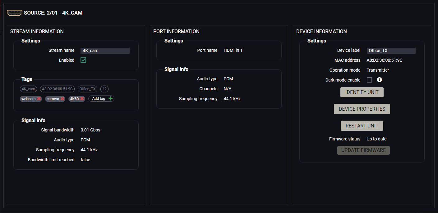
HDMI audio source port properties window
The most important signal information is available on the panel. #audio
Settings and Tools
▪Stream naming;
▪Enabled: when it is checked in, the stream is transmitted to the receiver; if it is not, the stream is muted.
▪Disconnect stream (only for the destination streams): clicking on the button results the source stream is disconnected from the output port.
▪Tags: unique and configurable tags can be attached to the stream for the best identification. The tags are searchable in the Search Field.
▪Dark mode: the dark mode feature can be enabled or disabled. It keeps the LCD screen and the LEDs unlit to hide the device during an event when the settings is enabled. #darkmode
▪Identify unit: Clicking on the button makes the four front panel LEDs blink in green for 10 seconds. The feature helps to identify the device itself in the rack shelf or on the desk.
▪Device properties: Clicking on the button opens the properties windows of the endpoint device.
▪Restart unit: clicking on the button makes rebooting the device (the same as disconnecting from the power source and reconnecting again).
8.11.2. Analog Audio Source Port Properties Window
Clicking on an analog audio source port the properties panel opens on the right side. Clicking on the icon the properties section opens in new window.
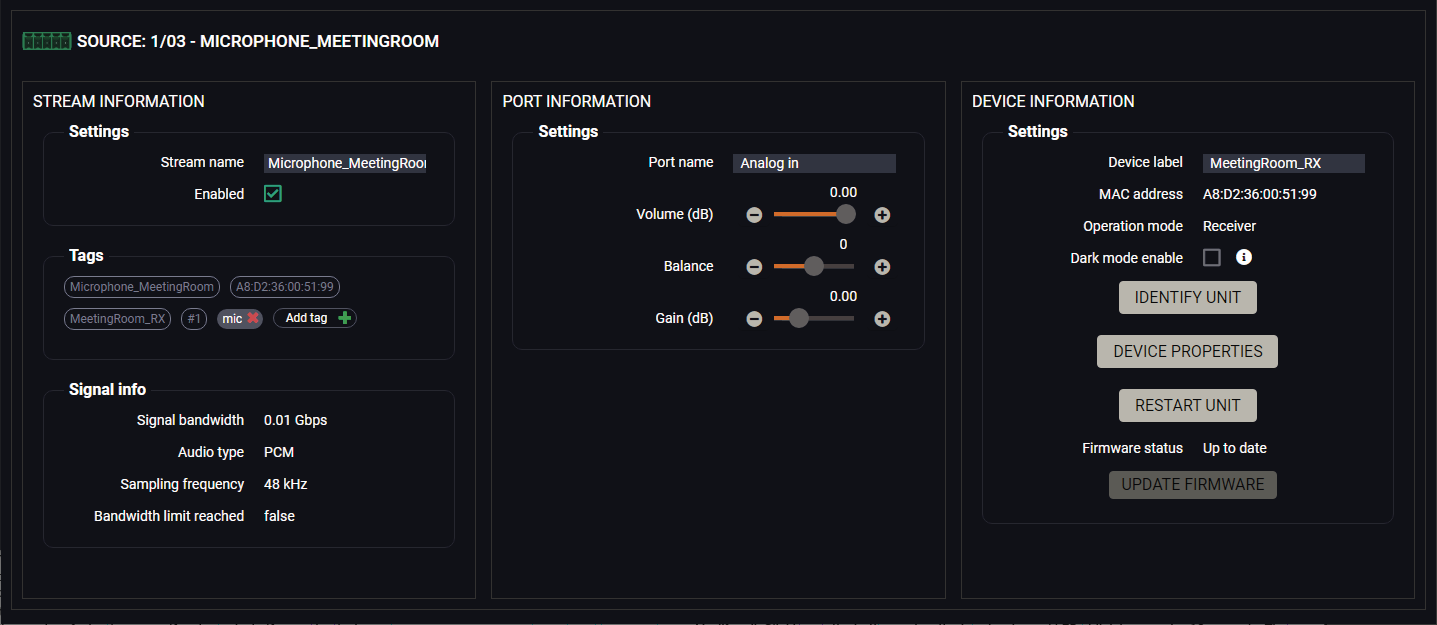
Analog audio source port properties window
The most important signal information is available on the panel. #analogaudio #volume #balance #gain
Settings and Tools
▪Stream naming;
▪Enabled: when it is checked in, the stream is transmitted to the receiver; if it is not, the stream is muted.
▪Tags: unique and configurable tags can be attached to the stream for the best identification. The tags are searchable in the Search Field.
▪Volume: sets the input volume (attenuation) between 0% (-95.62 dB) and 100% (0 dB). Clicking on the icon results in -1%, the icon results in +1% in the volume setting. The default value is 100%.
▪Balance: sets the balance between -100 (total left) and 100 (total right). Clicking on the icon results in -1, the icon results in +1 in the balance setting. The default value is 0 (center).
▪Gain: sets the gain between -12 dB and 35 dB. Clicking on the icon results in -1 dB, the icon results in +1 dB in the gain setting. The default value is 0 dB.
▪Dark mode: the dark mode feature can be enabled or disabled. It keeps the LCD screen and the LEDs unlit to hide the device during an event when the settings is enabled. #darkmode
▪Identify unit: Clicking on the button makes the four front panel LEDs blink in green for 10 seconds. The feature helps to identify the device itself in the rack shelf or on the desk.
▪Device properties: Clicking on the button opens the properties windows of the endpoint device.
▪Restart unit: clicking on the button makes rebooting the device (the same as disconnecting from the power source and reconnecting again).
8.11.3. Analog Audio Destination Port Properties Window
Clicking on an analog audio destination port the properties panel opens on the right side. Clicking on the icon the properties section opens in new window.
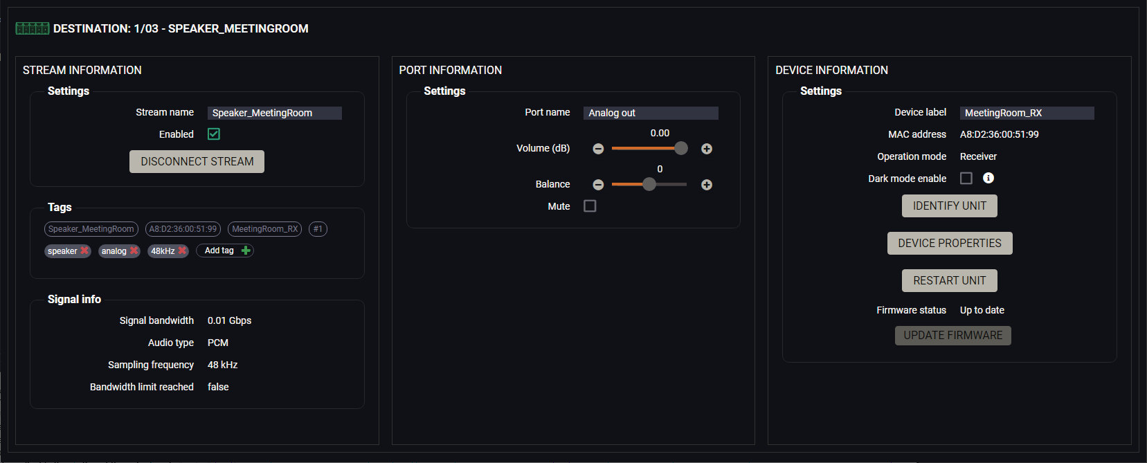
Analog audio destination port properties window
The most important signal information is available on the panel. #analogaudio #volume #balance #gain
Settings and Tools
▪Stream naming;
▪Enabled: when it is checked in, the stream is transmitted to the receiver; if it is not, the stream is muted.
▪Disconnect stream: clicking on the button results the source stream is disconnected from the output port.
▪Tags: unique and configurable tags can be attached to the stream for the best identification. The tags are searchable in the Search Field.
▪Volume: sets the input volume (attenuation) between 0% (-95.62 dB) and 100% (0 dB). Clicking on the icon results in -1%, the icon results in +1% in the volume setting. The default value is 100%.
▪Balance: sets the balance between -100 (total left) and 100 (total right). Clicking on the icon results in -1, the icon results in +1 in the balance setting. The default value is 0 (center).
▪Mute: enable or disable the muting of the output port. #mute #unmute
▪Dark mode: the dark mode feature can be enabled or disabled. It keeps the LCD screen and the LEDs unlit to hide the device during an event when the settings is enabled. #darkmode
▪Identify unit: Clicking on the button makes the four front panel LEDs blink in green for 10 seconds. The feature helps to identify the device itself in the rack shelf or on the desk.
▪Device properties: Clicking on the button opens the properties windows of the endpoint device.
▪Restart unit: clicking on the button makes rebooting the device (the same as disconnecting from the power source and reconnecting again).
8.12. Device Properties Windows
Port Tiles
The port tiles and the colors of the displayed icons represent different states and information.
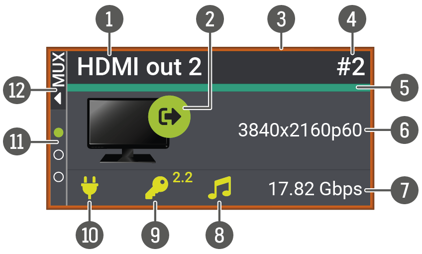
|
1 |
Port name |
||
|
2 |
Input / output port type indicator |
||
|
|
HDMI input port |
||
|
|
Local HDMI output port |
||
|
|
HDMI output port (the signal source is one of the input streams) |
||
|
|
HDMI output port (the signal source is the copy of the HDMI out 1) |
||
|
|
Analog audio input port |
||
|
|
Analog audio output port |
||
|
3 |
Selected port indicator If the frame is orange, the properties panel of the port is displayed. |
||
|
4 |
Port ID |
||
|
5 |
Signal present indicator If turquoise, signal is present, if grey, signal is not present. |
||
|
6 |
Resolution / refresh rate of the stream |
||
|
7 |
Bandwidth of the stream |
||
|
8 |
Embedded audio presence |
||

|
Embedded audio is present. |
||

|
Embedded audio is not present. |
||
|
9 |
HDCP state |
||

|
The signal is encrypted with HDCP 2.2. |
||

|
The signal is encrypted with HDCP 1.4. |
||

|
The sink device is not compatible with the current HDCP version. |
||

|
Signal is not HDCP-encrypted. |
||
|
q |
+5V / Hotplug state |
||

|
Source/sink is connected. |
||

|
Source/sink is not connected. |
||
|
w |
Source multiplexer (MUX) selector |
||
|
|
The selected source is the Stream (coming from the SFP+ ports). |
||
|
|
The selected source is the local HDMI input port. |
||
|
|
The selected source is the copy of the HDMI out 1 port. |
||
|
|
Selectable source signal |
||
|
e |
Source multiplexer (MUX) expandable menu Clicking here results opening the MUX menu with the selectable source signals of the output port. |
||
8.12.1. Transmitter Operation Mode
Clicking on the HDMI input 1 or 2 port icon results opens the Port properties. The most important signal information and settings are available from the panel.
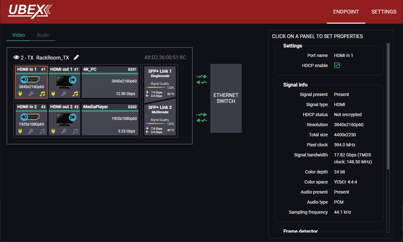
Endpoint tab of the Device properties window - Transmitter - Input port properties
Available Settings and Tools
▪HDCP setting (Enable / Disable); #hdcp
▪Frame Detector - The tool displays the frame information of the original stream coming from the input port before a possible rescaling / frame rate conversion.
INFO:The properties panel belongs to the local HDMI outputs of the transmitter.
Clicking on the HDMI output 1 or 2 port icon results in opens the Port properties. The most important signal and display information and settings are available from the panel.
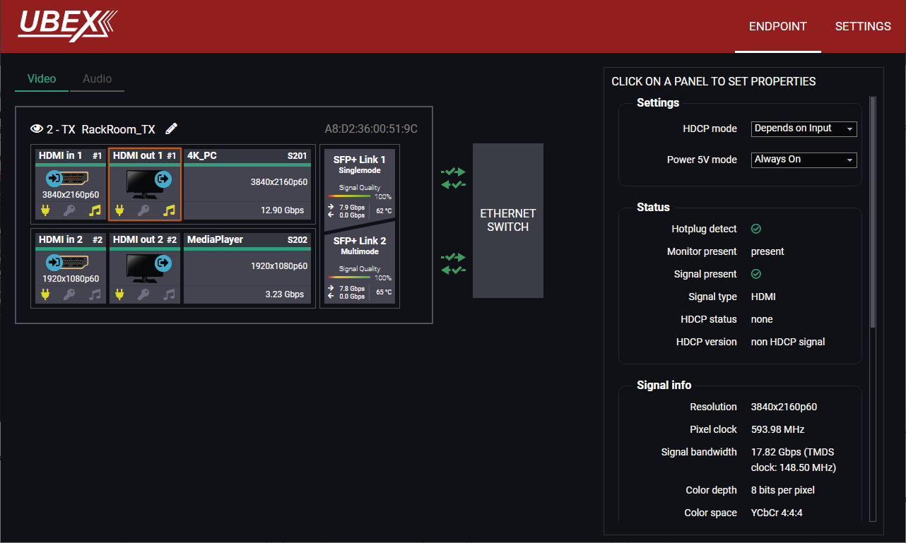
Endpoint tab of the Device properties window - Transmitter - Local output port properties
Available Settings and Tools
▪HDCP mode: #hdcp
=Depends on input: the level and version of HDCP-encryption depends on the source device;
=Maximum possible: the output ports set the maximum HDCP-encryption level that can be accepted by the connected sink device.
=Forced HDCP 2.2 Type 1: the output ports always force HDCP 2.2 Type 1. If the sink device supports this HDCP-encryption level, the signal will be encrypted with HDCP 2.2 Type 0/1. The signal will be encrypted with HDCP 2.2 Type 1 when the source and the sink both support this HDCP-encryption level.
▪Power 5V mode (Auto / Always on / Always off); #power5v
▪Frame Detector - The tool displays the frame information of the original stream coming from the input port before a possible rescaling / frame rate conversion.
Clicking on the Stream 1 or Stream 2 panels open the properties of the video input streams. The most important signal information and settings are available from the panel.
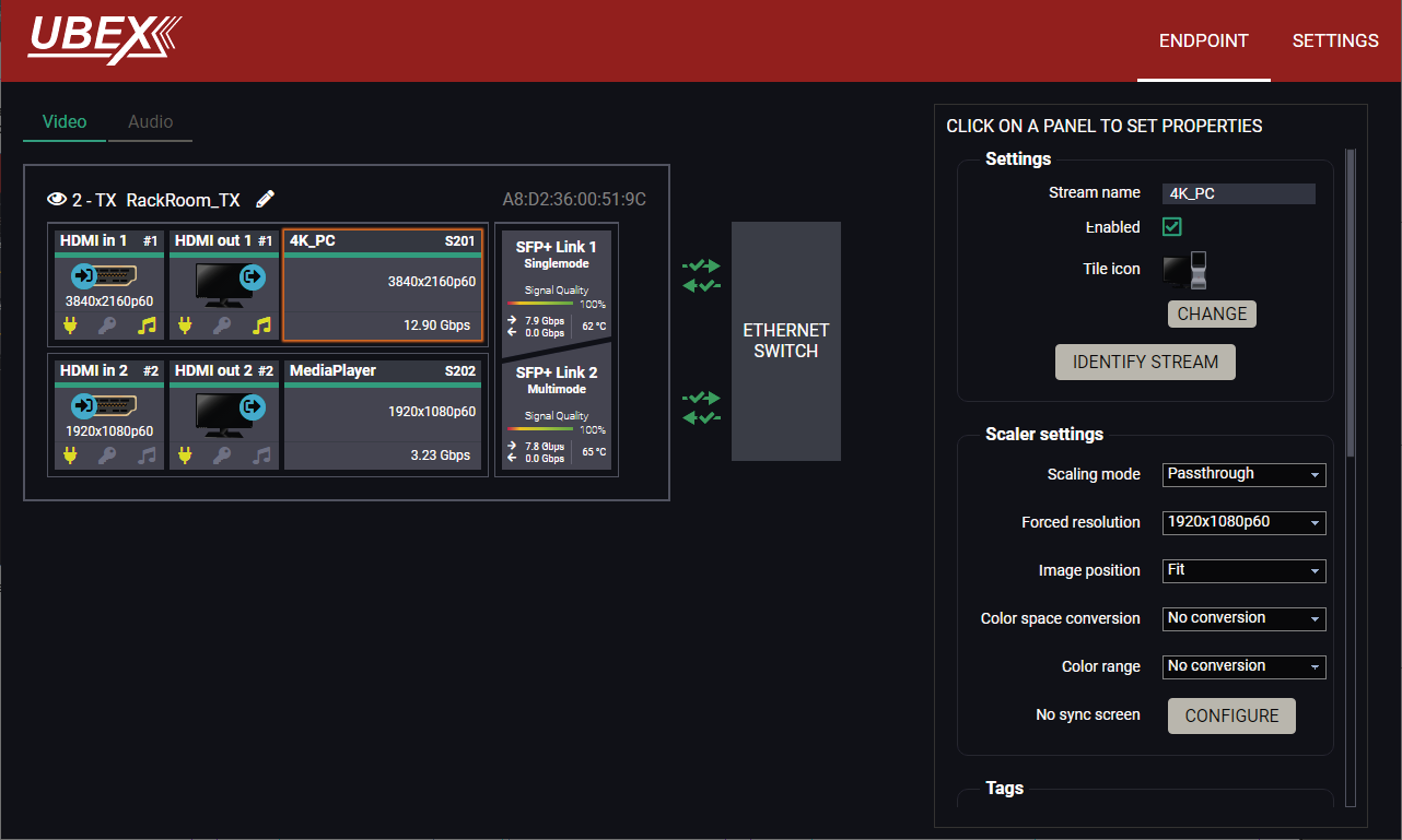
Endpoint tab of the Device properties window - Transmitter - Stream properties
Settings
▪Stream naming;
▪Enabled: when it is checked in, the stream is enabled; if it is not, the stream is muted. #streamenable
▪Tile icon: choose an icon which is the most suitable with the source/destination device connected to the endpoint.
▪Identify Stream / Identify Display. #identifystream #identifydisplay
Scaler Settings
▪Scaling mode:
=Passthrough: the scaler is in pass-through mode.
=Forced resolution: the scaling is active, the selected value in the forced resolution option will be applied to the video signal;
▪Forced resolution: list of the available resolutions with refresh rate values. The selected one will be applied to the video signal. See the available resolutions in the Resolutions of the Scaler section.
▪Image position (Stretch / Fit / Center)
DIFFERENCE:The transmitter is built with scaler function on HDMI input 2 port from firmware version v2.4.1. The Image position setting on this port is a read-only parameter and fixed as Center in case of previous firmware versions.
▪Color space conversion (No conversion / RGB / YCbCr 4:4:4 / YCbCr 4:2:2).
▪Color range (No conversion / Full range / Limited range);
▪Color depth setting (Pass / 8bpc / 10 bpc / 12 bpc)
▪No Sync Screen (Test Pattern).
Tags
Unique and configurable tags can be attached to the stream for the best identification. The tags are searchable in the Search Field.
Signal Info
All important information (resolution, pixel clock, color space, e.g.) are available in the signal info section. The signal bandwidth and the bandwidth limit reached indicators can also be checked in this panel.
Related Audio Info
Information (presence, audio type, sampling frequency) of the embedded audio is available in the related audio info section.
Tools
▪Frame Detector - The tool displays the frame information of the original stream coming from the input port before a possible rescaling / frame rate conversion.
Clicking on the SFP+ Link 1 or 2 panel opens the properties of the SFP+ connections. The most important signal information and the parameters of the SFP are available from the panel.
ATTENTION!If the icon appears, that means incompatible optical transceiver module is installed to the endpoint device (SFP optical module (1 GbE) instead of SFP+ module (10 GbE).
#scaler #frc #csc #colorspace #colorrange #colordepth #testpattern #nosyncscreen #tag #sfp
Link Aggregation Status Indicator
|
Icon |
Description |
|---|---|

|
SFP+ connection is established successfully and the link aggregation is working successfully. |

|
No connection is established between the SFP+ links. |
INFO:You can find possible causes and solution suggestions in the Troubleshooting chapter in the case of no connection or link aggregation problems.
Analog Audio Input Port Properties Panel
DIFFERENCE:Only the UBEX-PRO20-HDMI-F110, -F111, -F120, -F121 and F130 models are built with analog audio input port.
Clicking on the Analog in panel opens the properties of the port properties. The most important signal information and settings are available from the panel. #analogaudio #volume #balance #gain
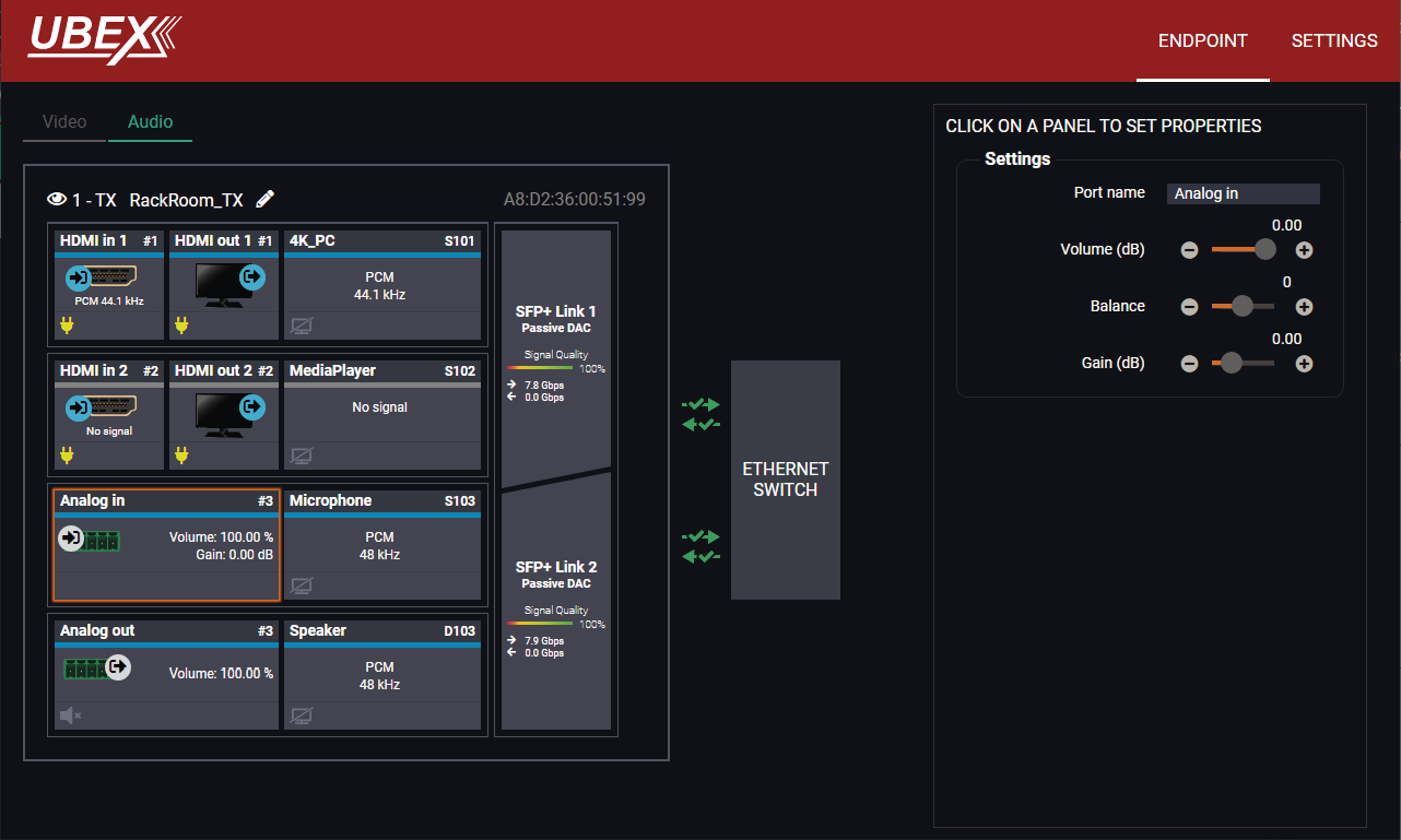
Endpoint tab of the Device properties window - Transmitter - Analog audio input port properties
Settings and Tools
▪Stream naming;
▪Volume: sets the input volume (attenuation) between 0% (-95.62 dB) and 100% (0 dB). Clicking on the icon results in -1%, the icon results in +1% in the volume setting. The default value is 100%.
▪Balance: sets the balance between -100 (total left) and 100 (total right). Clicking on the icon results in -1, the icon results in +1 in the balance setting. The default value is 0 (center).
▪Gain: sets the gain between -12 dB and 35 dB. Clicking on the icon results in -1 dB, the icon results in +1 dB in the gain setting. The default value is 0 dB.
Analog Audio Output Port Properties Panel
DIFFERENCE:Only the UBEX-PRO20-HDMI-F110, -F111, -F120, -F121 and F130 models are built with analog audio output port.
Clicking on the Analog out panel opens the properties of the port properties. The most important signal information and settings are available from the panel. #analogaudio #volume #balance #mute #unmute
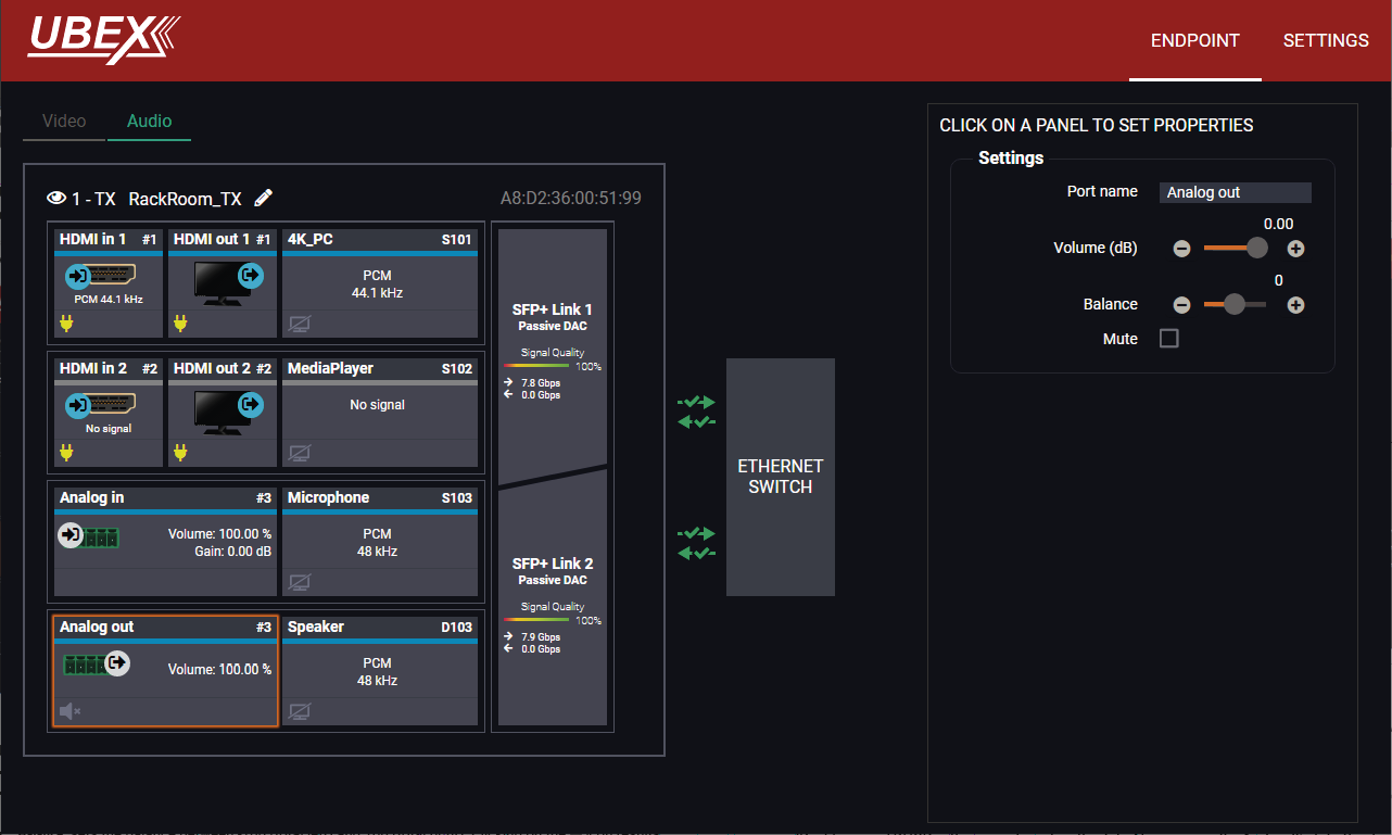
Endpoint tab of the Device properties window - Transmitter - Analog audio output port properties
Settings and Tools
▪Stream naming;
▪Volume: sets the input volume (attenuation) between 0% (-95.62 dB) and 100% (0 dB). Clicking on the icon results in -1%, the icon results in +1% in the volume setting. The default value is 100%.
▪Balance: sets the balance between -100 (total left) and 100 (total right). Clicking on the icon results in -1, the icon results in +1 in the balance setting. The default value is 0 (center).
▪Mute: enable or disable the muting of the output port.
Clicking on the Settings menu opens the settings panel of the endpoint.
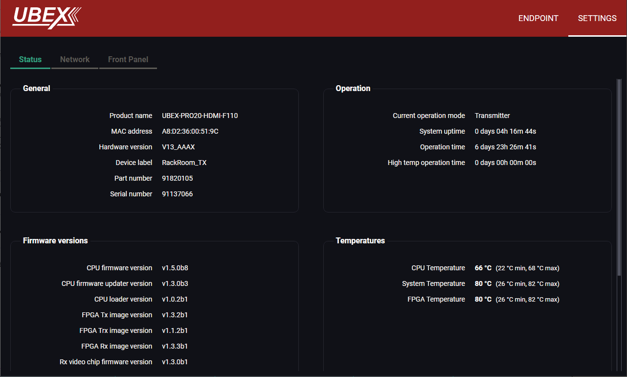
Settings tab of the Device properties window - Transmitter - Status tab
Status Tab
All important information are available about the transmitter, e.g. the MAC address of device, firmware versions, system uptime, voltages, and temperatures. #status #firmwareversion
Network Tab
ATTENTION!The network settings will be applied when the device is set to Extender mode. There is no public IP address of the endpoint device when it is in Matrix mode.
IP address and DHCP settings can be set on this tab. Always press the Apply settings button to save changes.
Factory defaults settings can be recalled with a dedicated button. See the factory default settings of the endpoint device in the Factory Default Settings section. #network #dhcp #ipaddress #mac
Front Panel Tab
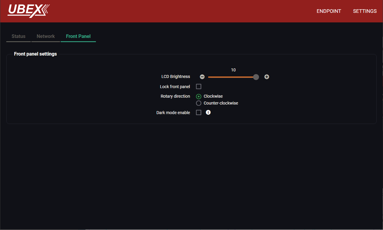
Settings tab of the Device properties window - Transmitter - Front panel tab
The following settings can be set under the Front panel tab:
▪LCD Brightness - the brightness of the LCD can be set from 1 to 10 on a scale.
▪Lock front panel - the operation of the jog dial control knob can be locked. The settings can be unlocked only by the LCD software or by an LW3 protocol command (see the details in the Control Lock section).
▪Rotary direction - the rotary direction of the jog dial control knob can be set in two ways:
=Clockwise
=Counter-clockwise #rotary #jogdial
▪Dark mode - the dark mode feature can be enabled or disabled. It keeps the LCD screen and the LEDs unlit to hide the device during an event when the settings is enabled. #darkmode
8.12.2. Receiver Operation Mode
Stream Properties Panels
Clicking on the Stream 1 or Stream 2 panels opens the properties of the video streams. The most important signal information and settings are available from the panel.
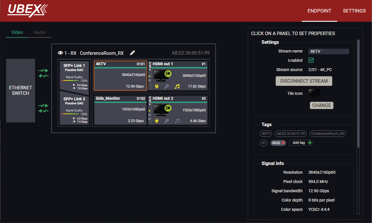
Endpoint tab of the Device properties window - Receiver - Stream Properties
Settings
▪Stream naming;
▪Enabled: when it is checked in, the stream is transmitted to the receiver; if it is not, the stream is muted.
▪Stream source: information about the currently connected stream and the ID of the source device.
▪Disconnect stream: clicking on the button results the source stream is disconnected from the output port.
▪Tile icon: choose an icon which is the most suitable with the source/destination device connected to the endpoint.
Tags
Unique and configurable tags can be attached to the stream for the best identification. The tags are searchable in the Search Field. #streamenable #tag #disconnect
Signal Info
All important information (resolution, pixel clock, color space, e.g.) are available in the signal info section. The signal bandwidth and the bandwidth limit reached indicators can also be checked in this panel.
Related Audio Info
Information (presence, audio type, sampling frequency) of the embedded audio is available in the related audio info section.
Tools
▪Frame Detector - The tool displays the frame information of the transmitted stream after a possible rescaling / frame rate conversion.
Clicking on the HDMI out 1 or 2 panels opens the properties of the output ports. The most important signal information and settings are available from the panel.
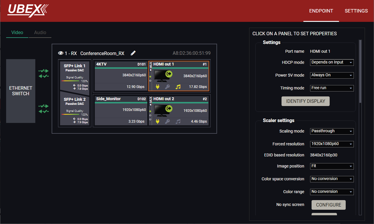
Endpoint tab of the Device properties window - Receiver - Output port properties
The source multiplexer (Source MUX) makes routing several different source signals to the HDMI output ports available. See more details about this function in the Receiver Mode section. #mux #sourcemux
Click on the MUX menu to expand the source MUX selector.
ATTENTION!The audio crosspoint settings always follow the source MUX settings of the video layer and the MUX settings cannot be set in the audio layer.
TIPS AND TRICKS:The source of the output port can also be selected without expanding the MUX menu.
HDMI Out 1
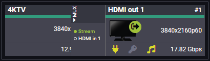
▪Stream - The signal source of the output port is the stream coming from the remote device.
▪HDMI in 1 - The signal source of the output port is the stream of the local input port of the receiver. The HDMI in 1 port panel will be available when selecting this option.
HDMI Out 2
▪Stream - The signal source of the output port is the stream coming from the remote device.
▪HDMI in 2- The signal source of the output port is the stream of the local input port of the receiver. The HDMI in 2 port panel will be available when selecting this option.
▪Copy - The device is able to copy the signal of the HDMI out 1 port. This is the COPY function.
INFO:The Copy function is available only on the HDMI out 2 port.
Settings
▪HDCP mode: #hdcp
=Depends on input: the level and version of HDCP-encryption depends on the source device;
=Maximum possible: the output ports set the maximum HDCP-encryption level that can be accepted by the connected sink device.
=Forced HDCP 2.2 Type 1: the output ports always force HDCP 2.2 Type 1. If the sink device supports this HDCP-encryption level, the signal will be encrypted with HDCP 2.2 Type 0/1. The signal will be encrypted with HDCP 2.2 Type 1 when the source and the sink both support this HDCP-encryption level.
▪Power 5V mode (Auto / Always on / Always off); #power5v
▪Timing mode (Free run / Source locked); #timingmode #freerun #sourcelocked
ATTENTION!When the Source locked mode setting was unsuccessful and the port uses Free run mode as fallback, an icon appears beside the settings. It may be caused by that the scaler / FRC setting is not in Pass-through mode or the resolution of the source stream is not the same as the destination stream's one.
▪Identify Stream / Identify Display. #identifystream #identifydisplay
Scaler Settings
DIFFERENCE:The receiver is built with scaler function on both HDMI output ports from firmware version v2.1.0. The Image position setting on this port is a read-only parameter and fixed as Center in case of previous firmware versions.
▪Scaling mode:
=Passthrough: the scaler is in pass-through mode.
=Forced resolution: the scaling is active, the selected value in the forced resolution option will be applied to the video signal;
=EDID based: the scaler forces the resolution that is read out from the EDID of the connected sink device.
▪Forced resolution: list of the available resolutions with refresh rate values. The selected one will be applied to the video signal. See the available resolutions in the Resolutions of the Scaler section.
▪EDID based resolution: the resolution that is read out from the EDID of the connected sink device.
▪Image position (Stretch / Fit / Center);
▪Color space conversion (No conversion / RGB / YCbCr 4:4:4 / YCbCr 4:2:2);
▪Color range (No conversion / Full range / Limited range);
▪Color depth setting (Pass / 8bpc / 10 bpc / 12 bpc)
▪No Sync Screen (Test Pattern);
▪Signal freeze button: the signal freezes at the last video frame on the sink device (the sink may show a broken frame too).
#scaler #frc #csc #colorspace #colorrange #colordepth #testpattern #nosyncscreen #freeze
Status / Signal Info
All important information (e.g. hotplug detect, HDCP status, resolution, total size, pixel clock, color space, e.g.) are available in the status and signal info sections.
Display Info
All related information about the sink device connected to the output port.
Tools
▪Frame Detector - The tool displays the frame information of the transmitted stream after a possible rescaling / frame rate conversion.
INFO:The properties panel appears only in case of the selected source MUX settings is the HDMI in 1 or 2 for the HDMI output ports.
INFO:The properties panel belongs to the local HDMI inputs of the receiver.
Clicking on the HDMI input 1 or 2 port icon results opens the Port properties. The most important signal information and settings are available from the panel.
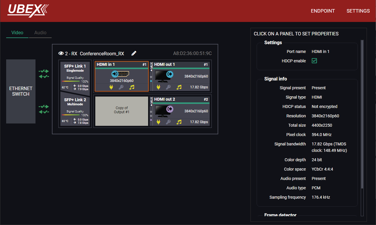
Endpoint tab of the Device properties window - Receiver - Local input port properties
Available Settings and Tools
▪HDCP setting (Enable / Disable); #hdcp
▪Frame Detector - The tool displays the frame information of the original stream coming from the input port before a possible rescaling / frame rate conversion.
Clicking on the SFP+ Link 1 or 2 panel opens the properties of the SFP+ connections. The most important signal information and the parameters of the SFP are available from the panel. #sfp
ATTENTION!If the icon appears, that means incompatible optical transceiver module is installed to the endpoint device (SFP optical module (1 GbE) instead of SFP+ module (10 GbE).
Link Aggregation Status Indicator
|
Icon |
Description |
|---|---|

|
SFP+ connection is established successfully and the link aggregation is working successfully. |

|
No connection is established between the SFP+ links. |
INFO:You can find possible causes and solution suggestions in the Troubleshooting chapter in the case of no connection or link aggregation problems.
Analog Audio Input Port Properties Panel
DIFFERENCE:Only the UBEX-PRO20-HDMI-F110, -F111, -F120, -F121 and F130 models are built with analog audio input port.
Clicking on the Analog in panel opens the properties of the port properties. The most important signal information and settings are available from the panel. #analogaudio #volume #balance #gain
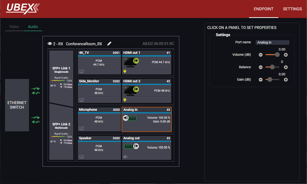
Endpoint tab of the Device properties window - Receiver - Analog audio input port properties
Settings and Tools
▪Stream naming;
▪Volume: sets the input volume (attenuation) between 0% (-95.62 dB) and 100% (0 dB). Clicking on the icon results in -1%, the icon results in +1% in the volume setting. The default value is 100%.
▪Balance: sets the balance between -100 (total left) and 100 (total right). Clicking on the icon results in -1, the icon results in +1 in the balance setting. The default value is 0 (center).
▪Gain: sets the gain between -12 dB and 35 dB. Clicking on the icon results in -1 dB, the icon results in +1 dB in the gain setting. The default value is 0 dB.
ATTENTION!The audio crosspoint settings always follow the source MUX settings of the video layer and the MUX settings cannot be set in the audio layer.
Analog Audio Output Port Properties Panel
DIFFERENCE:Only the UBEX-PRO20-HDMI-F110, -F111, -F120, -F121 and F130 models are built with analog audio output port.
Clicking on the Analog out panel opens the properties of the port properties. The most important signal information and settings are available from the panel. #analogaudio #volume #balance #mute #unmute
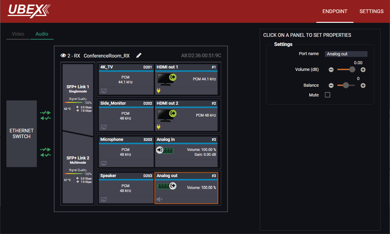
Endpoint tab of the Device properties window - Receiver - Analog audio output port properties
Settings and Tools
▪Stream naming;
▪Volume: sets the input volume (attenuation) between 0% (-95.62 dB) and 100% (0 dB). Clicking on the icon results in -1%, the icon results in +1% in the volume setting. The default value is 100%.
▪Balance: sets the balance between -100 (total left) and 100 (total right). Clicking on the icon results in -1, the icon results in +1 in the balance setting. The default value is 0 (center).
▪Mute: enable or disable the muting of the output port.
ATTENTION!The audio crosspoint settings always follow the source MUX settings of the video layer and the MUX settings cannot be set in the audio layer.
Clicking on the Settings menu opens the settings panel of the endpoint.
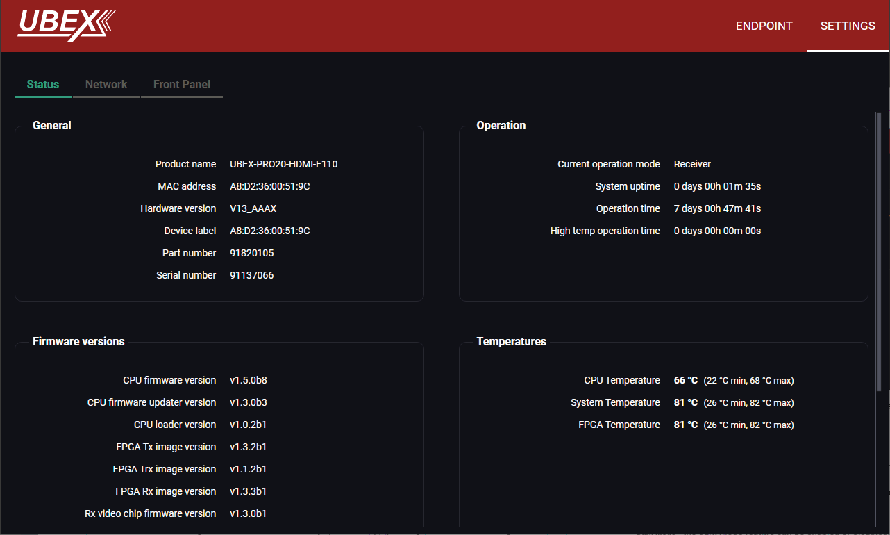
Settings tab of the Device properties window - Receiver - Network tab
Status Tab
All important information are available about the receiver, e.g. the MAC address of device, firmware versions, system uptime, voltages, and temperatures. #status #firmwareversion
Network Tab
ATTENTION!The network settings will be applied when the device is set to Extender mode. There is no public IP address of the endpoint device when it is in Matrix mode.
IP address and DHCP settings can be set on this tab. Always press the Apply settings button to save changes.
Factory defaults settings can be recalled with a dedicated button. See the factory default settings of the endpoint device in the Factory Default Settings section. #network #dhcp #ipaddress #mac
Front Panel Tab
Settings tab of the Device properties window - Receiver - Front panel tab
The following settings can be set under the Front panel tab:
▪LCD Brightness - the brightness of the LCD can be set from 1 to 10 on a scale.
▪Lock front panel - the operation of the jog dial control knob can be locked. The settings can be unlocked only by the LCD software or by an LW3 protocol command (see the details in the Control Lock section).
▪Rotary direction - the rotary direction of the jog dial control knob can be set in two ways:
=Clockwise
=Counter-clockwise #rotary #jogdial
▪Dark mode - the dark mode feature can be enabled or disabled. It keeps the LCD screen and the LEDs unlit to hide the device during an event when the settings is enabled. #darkmode
8.12.3. Transceiver Operation Mode
Clicking on the HDMI out 1 panel opens the properties of the output port. The most important signal information and settings are available from the panel.
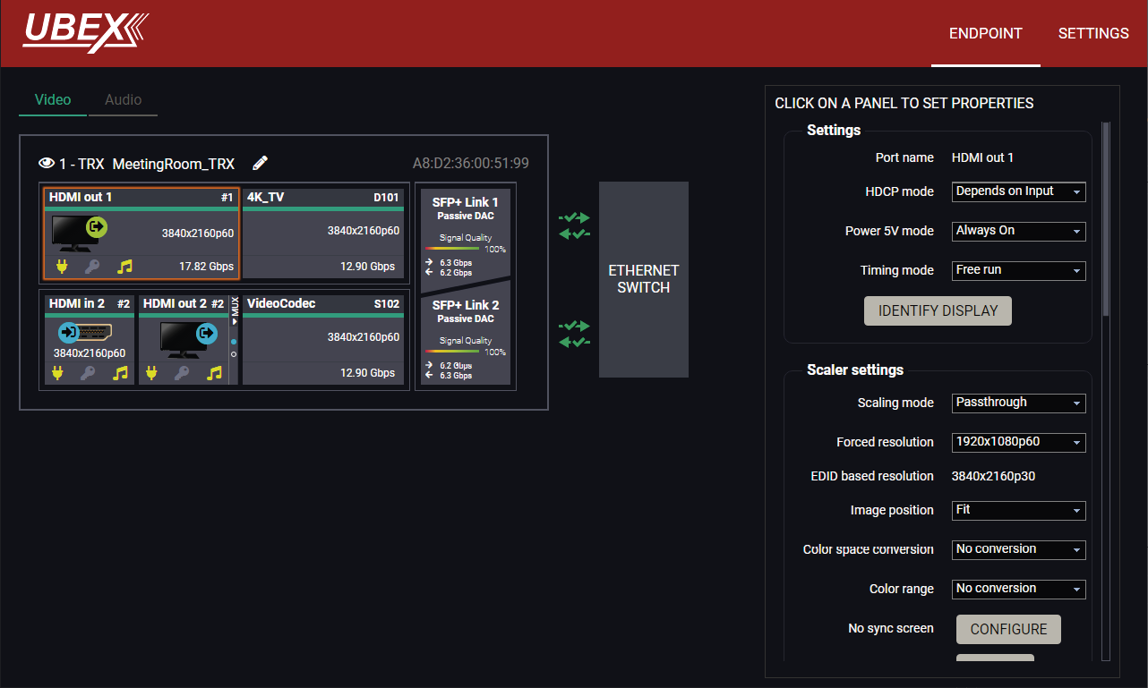
Endpoint tab of the Device properties window - Transceiver - Output port properties
Settings
▪HDCP mode: #hdcp
=Depends on input: the level and version of HDCP-encryption depends on the source device;
=Maximum possible: the output ports set the maximum HDCP-encryption level that can be accepted by the connected sink device.
=Forced HDCP 2.2 Type 1: the output ports always force HDCP 2.2 Type 1. If the sink device supports this HDCP-encryption level, the signal will be encrypted with HDCP 2.2 Type 0/1. The signal will be encrypted with HDCP 2.2 Type 1 when the source and the sink both support this HDCP-encryption level.
▪Power 5V mode (Auto / Always on / Always off); #power5v
▪Timing mode (Free run / Source locked); #timingmode #freerun #sourcelocked
ATTENTION!When the Source locked mode setting was unsuccessful and the port uses Free run mode as fallback, an icon appears beside the settings. It may be caused by that the scaler / FRC setting is not in Pass-through mode or the resolution of the source stream is not the same as the destination stream's one.
▪Identify Stream / Identify Display. #identifystream #identifydisplay
Scaler Settings
▪Scaling mode:
=Passthrough: the scaler is in pass-through mode.
=Forced resolution: the scaling is active, the selected value in the forced resolution option will be applied to the video signal;
=EDID based: the scaler forces the resolution that is read out from the EDID of the connected sink device.
▪Forced resolution: list of the available resolutions with refresh rate values. The selected one will be applied to the video signal. See the available resolutions in the Resolutions of the Scaler section.
▪EDID based resolution: the resolution that is read out from the EDID of the connected sink device.
▪Image position (Stretch / Fit / Center);
▪Color space conversion (No conversion / RGB / YCbCr 4:4:4 / YCbCr 4:2:2);
▪Color range (No conversion / Full range / Limited range);
▪Color depth setting (Pass / 8bpc / 10 bpc / 12 bpc)
▪No Sync Screen (Test Pattern);
▪Signal freeze button: the signal freezes at the last video frame on the sink device (the sink may show a broken frame too). #scaler #frc #csc #colorspace #colordepth #colorrange #testpattern #nosyncscreen #freeze
Status / Signal Info
All important information (e.g. hotplug detect, HDCP status, resolution, total size, pixel clock, color space, e.g.) are available in the status and signal info sections.
Display Info
All related information about the sink device connected to the output port.
Tools
▪Frame Detector - The tool displays the frame information of the transmitted stream after a possible rescaling / frame rate conversion.
Destination Stream Panel
Clicking on the destination stream panel opens the properties of the stream. The most important signal information and settings are available from the panel.
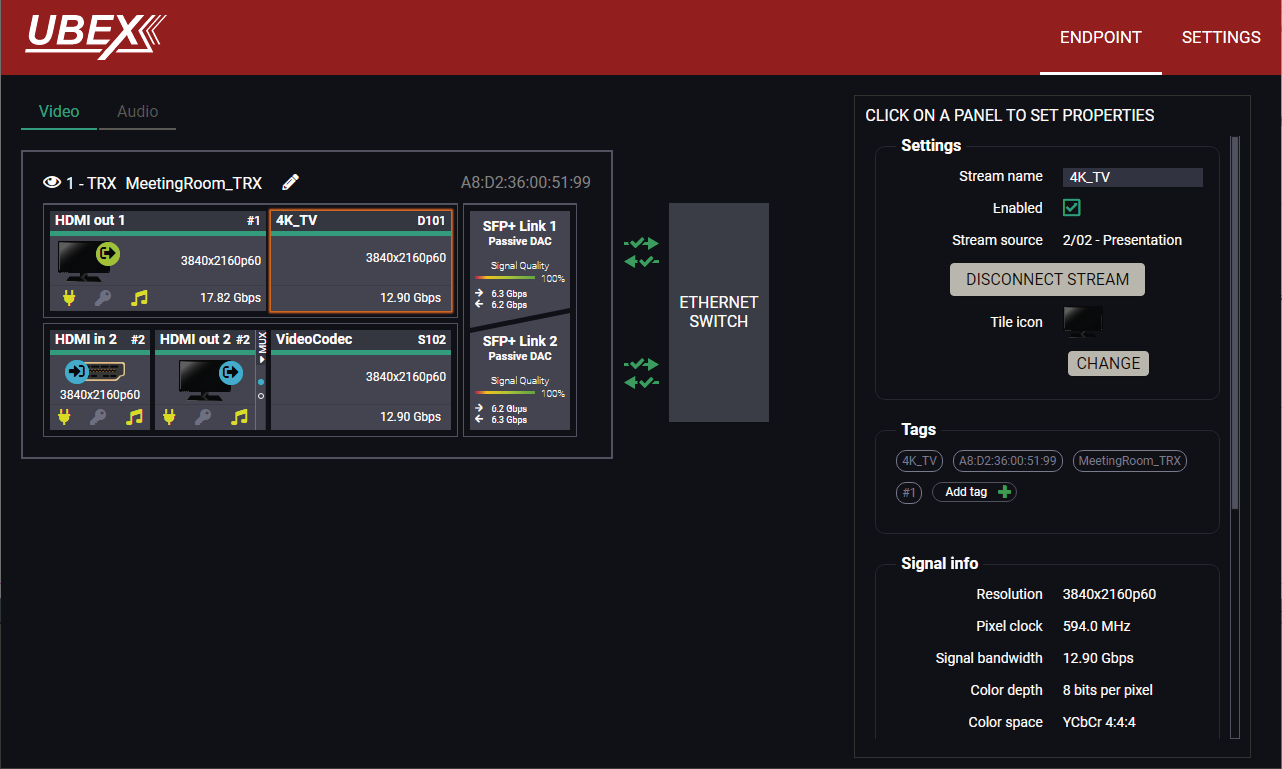
Endpoint tab of the Device properties window - Transceiver - Destination stream properties
Settings
▪Stream naming;
▪Enabled: when it is checked in, the stream is transmitted to the receiver; if it is not, the stream is muted.
▪Stream source: information about the currently connected stream and the ID of the source device.
▪Disconnect stream: clicking on the button results the source stream is disconnected from the output port. #disconnect
▪Tile icon: choose an icon which is the most suitable with the source/destination device connected to the endpoint.
Tags
Unique and configurable tags can be attached to the stream for the best identification. The tags are searchable in the Search Field. #streamenable #tag
Signal Info
All important information (resolution, pixel clock, color space, e.g.) are available in the signal info section. The signal bandwidth and the bandwidth limit reached indicators can also be checked in this panel.
Related Audio Info
Information (presence, audio type, sampling frequency) of the embedded audio is available in the related audio info section.
Tools
▪Frame Detector - The tool displays the frame information of the transmitted stream after a possible rescaling / frame rate conversion.
HDMI In 2 Panel
Clicking on the HDMI in 2 panel opens the properties of the input port. The most important signal information and settings are available from the panel.
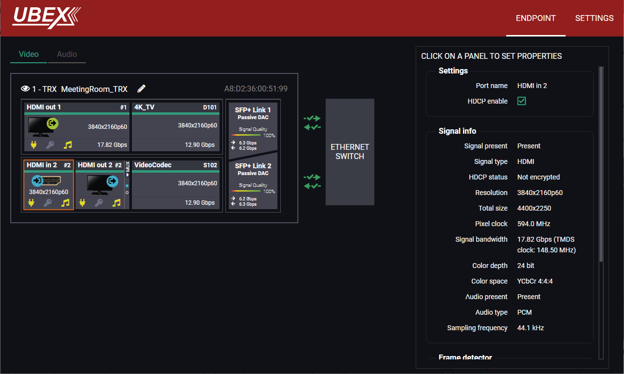
Endpoint tab of the Device properties window - Transceiver - Input port properties
Available Settings and Tools
▪HDCP setting (Enable / Disable); #hdcp
▪Frame Detector - The tool displays the frame information of the original stream coming from the input port before a possible rescaling / frame rate conversion.
INFO:The properties panel belongs to the local HDMI output of the transceiver.
Clicking on the HDMI output 2 port icon results in opens the Port properties. The most important signal and display information and settings are available from the panel.
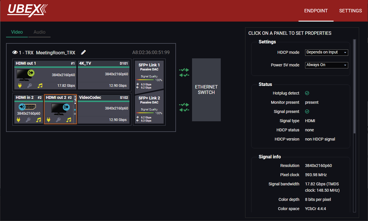
Endpoint tab of the Device properties window - Transceiver - Local output port properties
The source multiplexer (Source MUX) makes routing several different source signals to the HDMI output ports available. See more details about this function in the Transceiver Mode section. #mux #sourcemux
Click on the MUX menu to expand the source MUX selector.
ATTENTION!The audio crosspoint settings always follow the source MUX settings of the video layer and the MUX settings cannot be set in the audio layer.
TIPS AND TRICKS:The source of the output port can also be selected without expanding the MUX menu.
HDMI Out 2
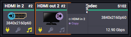
▪HDMI in 2- The signal source of the local output port is the stream of the local input port of the transceiver.
▪Copy - The device is able to copy the signal of the HDMI out 1 port. This is the COPY function.
Available Settings and Tools
▪HDCP mode: #hdcp
=Depends on input: the level and version of HDCP-encryption depends on the source device;
=Maximum possible: the output ports set the maximum HDCP-encryption level that can be accepted by the connected sink device.
=Forced HDCP 2.2 Type 1: the output ports always force HDCP 2.2 Type 1. If the sink device supports this HDCP-encryption level, the signal will be encrypted with HDCP 2.2 Type 0/1. The signal will be encrypted with HDCP 2.2 Type 1 when the source and the sink both support this HDCP-encryption level.
▪Power 5V mode (Auto / Always on / Always off); #power5v
▪Frame Detector - The tool displays the frame information of the original stream coming from the input port before a possible rescaling / frame rate conversion.
Clicking on the source stream panel opens the properties of the stream. The most important signal information and settings are available from the panel.
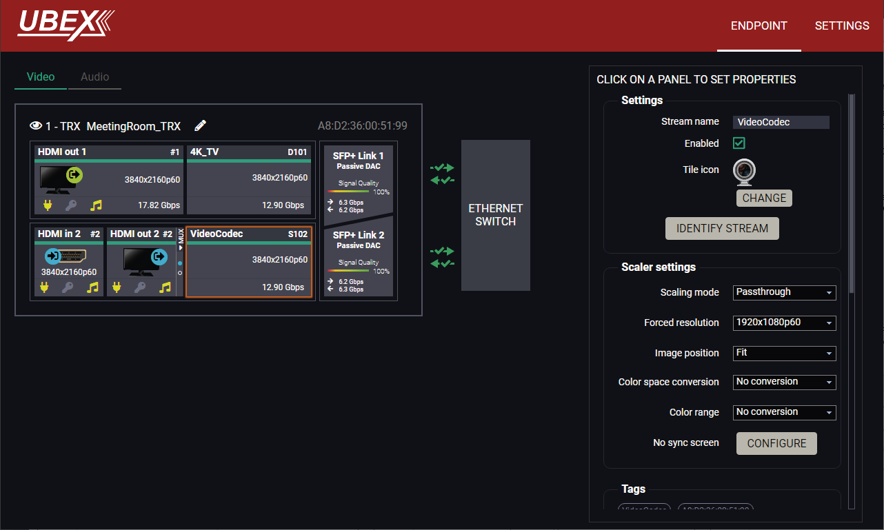
Endpoint tab of the Device properties window - Transceiver - Source stream properties
Settings
▪Stream naming;
▪Enabled: when it is checked in, the stream is enabled; if it is not, the stream is muted.
▪Tile icon: choose an icon which is the most suitable with the source/destination device connected to the endpoint.
▪Identify Stream / Identify Display. #identifystream #identifydisplay
Tags
Unique and configurable tags can be attached to the stream for the best identification. The tags are searchable in the Search Field.
#streamenable #tag
Scaler Settings
DIFFERENCE:The transceiver is built with scaler function on HDMI input 2 port from firmware version v2.1.0. The port has FRC and CSC settings only in case of previous firmwares.
▪Scaling mode:
=Passthrough: the scaler is in pass-through mode.
=Forced resolution: the scaling is active, the selected value in the forced resolution option will be applied to the video signal;
▪Forced resolution: list of the available resolutions with refresh rate values. The selected one will be applied to the video signal. See the available resolutions in the Resolutions of the Scaler section.
▪Image position (Stretch / Fit / Center)
▪Color space conversion (No conversion / RGB / YCbCr 4:4:4 / YCbCr 4:2:2).
▪Color range (No conversion / Full range / Limited range);
▪Color depth setting (Pass / 8bpc / 10 bpc / 12 bpc)
▪No Sync Screen (Test Pattern).
Signal Info
All important information (resolution, pixel clock, color space, e.g.) are available in the signal info section. The signal bandwidth and the bandwidth limit reached indicators can also be checked in this panel.
Related Audio Info
Information (presence, audio type, sampling frequency) of the embedded audio is available in the related audio info section.
Tools
▪Frame Detector - The tool displays the frame information of the original stream coming from the input port before a possible rescaling / frame rate conversion.
Clicking on the SFP+ Link 1 or 2 panel opens the properties of the SFP+ connections. The most important signal information and the parameters of the SFP are available from the panel. #sfp
ATTENTION!If the icon appears, that means incompatible optical transceiver module is installed to the endpoint device (SFP optical module (1 GbE) instead of SFP+ module (10 GbE).
Link Aggregation Status Indicator
|
Icon |
Description |
|---|---|

|
SFP+ connection is established successfully and the link aggregation is working successfully. |

|
No connection is established between the SFP+ links. |
INFO:You can find possible causes and solution suggestions in the Troubleshooting chapter in the case of no connection or link aggregation problems.
Analog Audio Input Port Properties Panel
DIFFERENCE:Only the UBEX-PRO20-HDMI-F110, -F111, -F120, -F121 and F130 models are built with analog audio input port.
Clicking on the Analog in panel opens the properties of the port properties. The most important signal information and settings are available from the panel. #analogaudio #volume #balance #gain
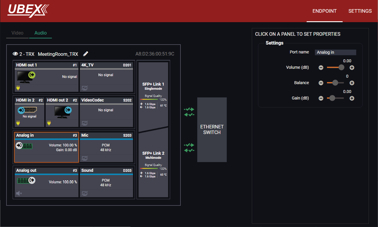
Endpoint tab of the Device properties window - Transceiver - Analog audio input port properties
Settings and Tools
▪Stream naming;
▪Volume: sets the input volume (attenuation) between 0% (-95.62 dB) and 100% (0 dB). Clicking on the icon results in -1%, the icon results in +1% in the volume setting. The default value is 100%.
▪Balance: sets the balance between -100 (total left) and 100 (total right). Clicking on the icon results in -1, the icon results in +1 in the balance setting. The default value is 0 (center).
▪Gain: sets the gain between -12 dB and 35 dB. Clicking on the icon results in -1 dB, the icon results in +1 dB in the gain setting. The default value is 0 dB.
ATTENTION!The audio crosspoint settings always follow the source MUX settings of the video layer and the MUX settings cannot be set in the audio layer.
Analog Audio Output Port Properties Panel
DIFFERENCE:Only the UBEX-PRO20-HDMI-F110, -F111, -F120, -F121 and F130 models are built with analog audio output port.
Clicking on the Analog out panel opens the properties of the port properties. The most important signal information and settings are available from the panel. #analogaudio #volume #balance #mute #unmute
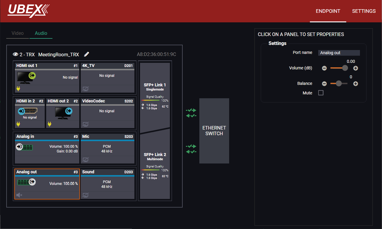
Endpoint tab of the Device properties window - Transceiver - Analog audio output port properties
Settings and Tools
▪Stream naming;
▪Volume: sets the input volume (attenuation) between 0% (-95.62 dB) and 100% (0 dB). Clicking on the icon results in -1%, the icon results in +1% in the volume setting. The default value is 100%.
▪Balance: sets the balance between -100 (total left) and 100 (total right). Clicking on the icon results in -1, the icon results in +1 in the balance setting. The default value is 0 (center).
▪Mute: enable or disable the muting of the output port.
ATTENTION!The audio crosspoint settings always follow the source MUX settings of the video layer and the MUX settings cannot be set in the audio layer.
Clicking on the Settings menu opens the settings panel of the endpoint.
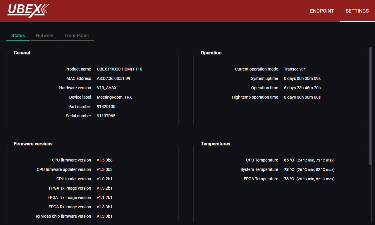
Settings tab of the Device properties window - Transceiver - Status tab
Status Tab
All important information are available about the transceiver, e.g. the MAC address of device, firmware versions, system uptime, voltages, and temperatures. #status #firmwareversion
Network Tab
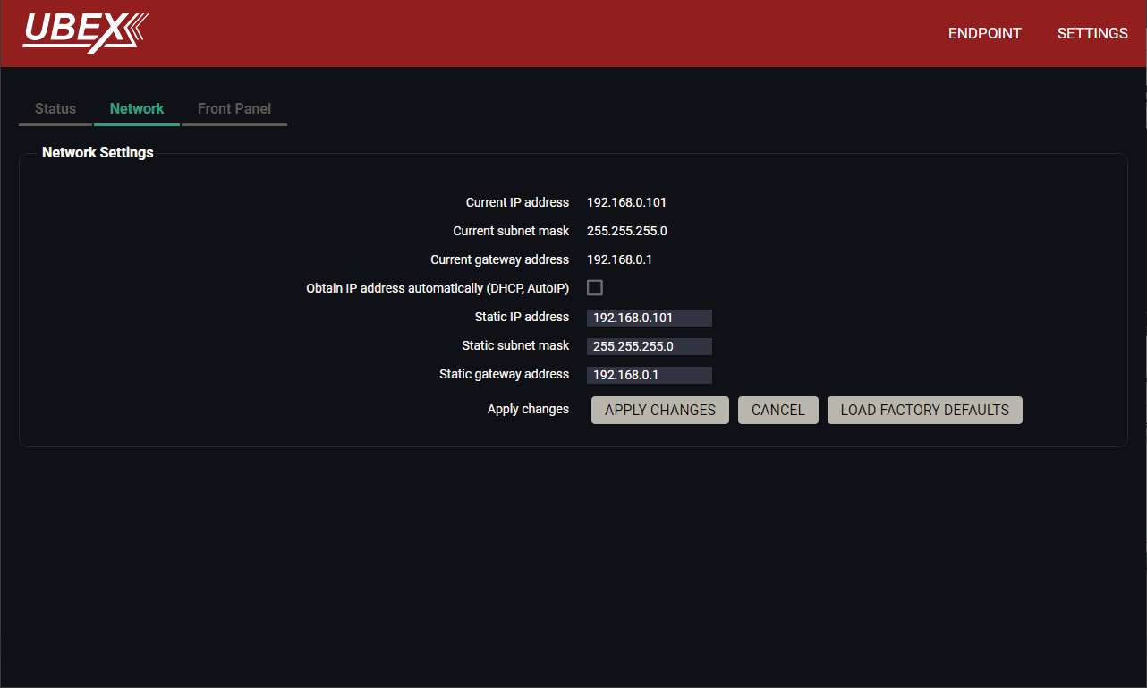
Settings tab of the Device properties window - Transceiver - Network tab
ATTENTION!The network settings will be applied when the device is set to Extender mode. There is no public IP address of the endpoint device when it is in Matrix mode.
IP address and DHCP settings can be set on this tab. Always press the Apply settings button to save changes.
Factory defaults settings can be recalled with a dedicated button. See the factory default settings of the endpoint device in the Factory Default Settings section. #network #dhcp #ipaddress #mac
Front Panel Tab
Settings tab of the Device properties window - Transceiver - Front panel tab
The following settings can be set under the Front panel tab:
▪LCD Brightness - the brightness of the LCD can be set from 1 to 10 on a scale.
▪Lock front panel - the operation of the jog dial control knob can be locked. The settings can be unlocked only by the LCD software or by an LW3 protocol command (see the details in the Control Lock section).
▪Rotary direction - the rotary direction of the jog dial control knob can be set in two ways:
=Clockwise
=Counter-clockwise #rotary #jogdial
▪Dark mode - the dark mode feature can be enabled or disabled. It keeps the LCD screen and the LEDs unlit to hide the device during an event when the settings is enabled. #darkmode
8.13. Diagnostic Tools
The ports can show detailed information about the signal like blanking intervals and active video resolution. This feature can be used for troubleshooting if compatibility problems occur during system installation. To access this function, open the port properties window and click on the Frame detector button.
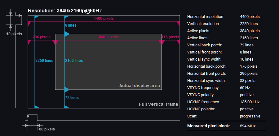
Frame detector window
Lightware’s Frame Detector function works like a signal analyzer and allows to determine the exact video format that is present on the port, thus it helps to identify various problems. E.g. actual timing parameters may differ from the expected and this may cause some displays to drop the picture.
Frame Detector measures detailed timings of the video signals just like a built-in oscilloscope, but it is much easier to use. Actual display area shows the active video size (dark grey). The black area of the full frame is the blanking interval, which can contain the info frames and embedded audio data for HDMI signals. Shown values are measured on the actual signal and not retrieved only from the HDMI info frames. #framedetector
8.13.2. No Sync Screen (Test Pattern)
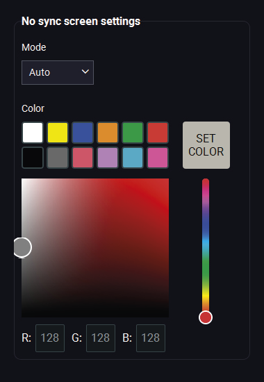
The No sync screen feature generates an image that can be displayed when there is no incoming signal on the port. The following settings can be set for the Test Pattern function:
Mode
▪Always on: the video output port always transmits the test pattern.
▪Auto: the video output port transmits the test pattern if there is no incoming signal on the selected input port.
▪Always off: the test pattern function is disabled, the video output port transmits the video signal of the selected input port.
▪Freeze: the signal freezes at the last video frame on the sink device (the sink may show a broken frame too). #freeze
Color
Three ways are available to set the no sync screen color:
▪Click on the predefined color;
▪Use the sliders;
▪Type the RGB code of the color.
When the desired color is selected, press the Set color button to store. #testpattern #nosyncscreen
Port Tile
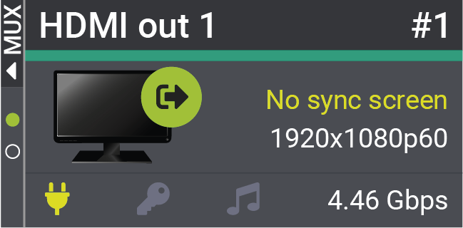
The port tile of the HDMI outputs displays when No sync screen mode is active.
INFO:No sync screen will be active in the case of connected sink device to the output port only.
8.13.3. Identify Stream / Identify Display
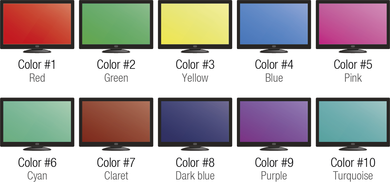
Clicking on the Identify Stream / Identify Display button generates 10 test colors on the display device for 10 seconds. The feature helps to identify the stream and the screen itself physically. #identifystream #identifydisplay
The order of the generated colors
Advanced EDID Management can be accessed by selecting the EDID Management menu. There are two panels: left one contains Source EDIDs, right one contains Destination places where the EDIDs can be emulated or copied. #edid
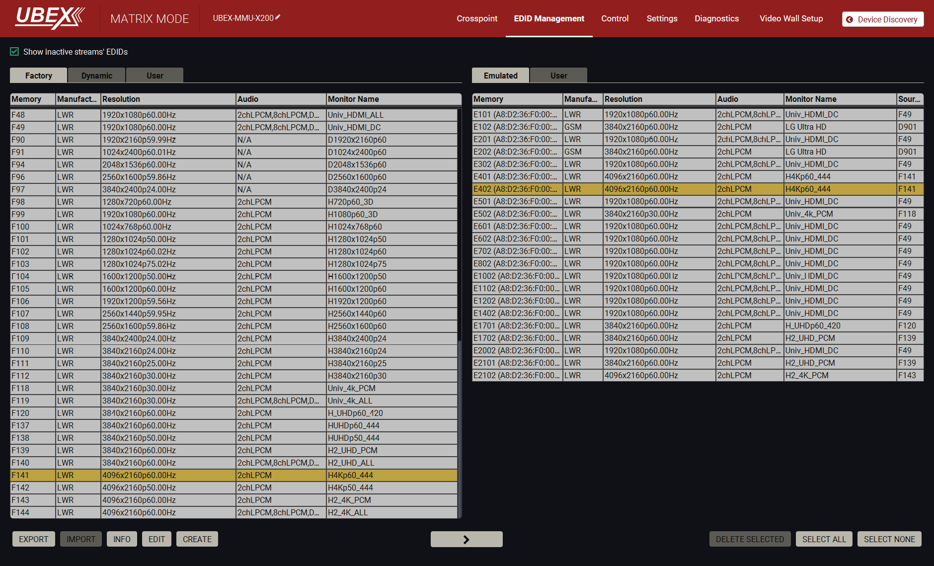
EDID Management menu
Control Buttons

|
Exporting an EDID (save to a file) |
|
Transfer button: executing EDID emulation or copying |

|
Importing an EDID (load from a file) |

|
Deleting EDID (from User memory) |

|
Display EDID Summary window |

|
Selecting all memory places in the right panel |

|
Opening Advanced EDID Editor with the selected EDID |

|
Selecting none of the memory places in the right panel |

|
Opening Easy EDID Creator |
Changing Emulated EDID
Step 1.Choose the desired EDID list on the source panel and select an EDID.
Step 2.Press the Emulated button on the top of the Destination panel.
Step 3.Select the desired port on the right panel (one or more ports can be selected); the EDID(s) will be highlighted with a yellow cursor.
Step 4.Press the Transfer button to change the emulated EDID.
Learning an EDID
The process is the same as changing the emulated EDID; the only difference is the Destination panel: press the User button. Thus, one or more EDIDs can be copied into the user memory either from the factory memory or from a connected sink (Dynamic).
Exporting an EDID

Source EDID can be downloaded as a file (*.bin, *.dat or *.edid) to the computer.
Step 1.Select the desired EDID from the Source panel (line will be highlighted with yellow).
Step 2.Press the Export button to open the dialog box and save the file to the computer.
Importing an EDID

Previously saved EDID (*.bin, *.dat or *.edid file) can be uploaded to the user memory:
Step 1.Press the User button on the top of the Source panel and select a memory slot.
Step 2.Press the Import button below the Source panel.
Step 3.Browse the file in the opening window, then press the Open button. Browsed EDID is imported into the selected User memory.
ATTENTION!The imported EDID overwrites the selected memory place even if it is not empty.
Deleting EDID(s)

The EDID(s) from User memory can be deleted as follows:
Step 1.Press User button on the top of the Destination panel.
Step 2.Select the desired memory slot(s); one or more can be selected (“Select All” and “Select None” buttons can be used). The EDID(s) will be highlighted with yellow.
Step 3.Press the Delete selected button to delete the EDID(s).

Select an EDID from Source panel and press the Edit button to display the Advanced EDID Editor window. The editor can read and write all descriptors that are defined in the standards, including the additional CEA extensions. Any EDID from the device’s memory or a saved EDID file can be loaded into the editor. The software resolves the raw EDID and displays it as readable information to the user. All descriptors can be edited and saved in an EDID file, or uploaded to the User memory. For more details about EDID Editor, please visit our website (https://go.lightware.com/edid-editor-application-notes) and download the EDID Editor user manual.
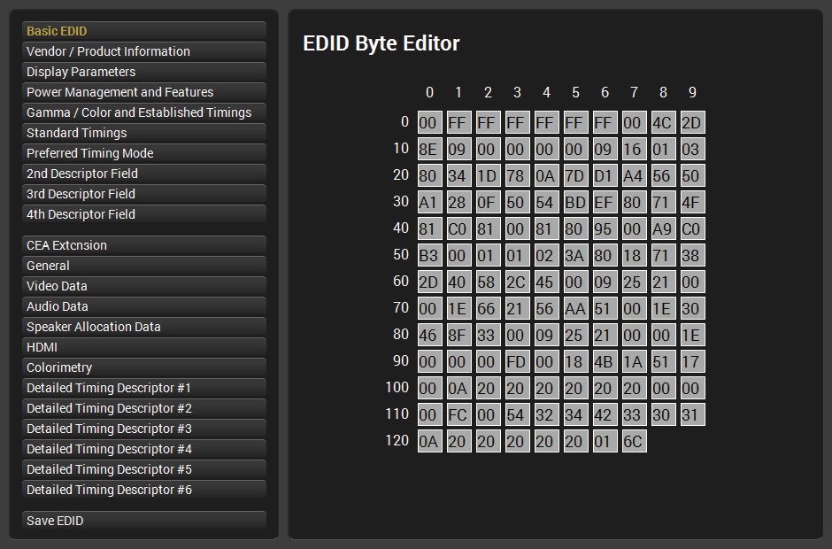
EDID Editor window
8.14.3. Creating an EDID - Easy EDID Creator

Since the above mentioned Advanced EDID Editor needs more detailed knowledge about EDID, Lightware introduced a wizard-like interface for fast and easy EDID creation. With Easy EDID Creator it is possible to create custom EDIDs in four simple steps. By clicking on the Create button below the Source panel, Easy EDID Creator is opened in a new window.
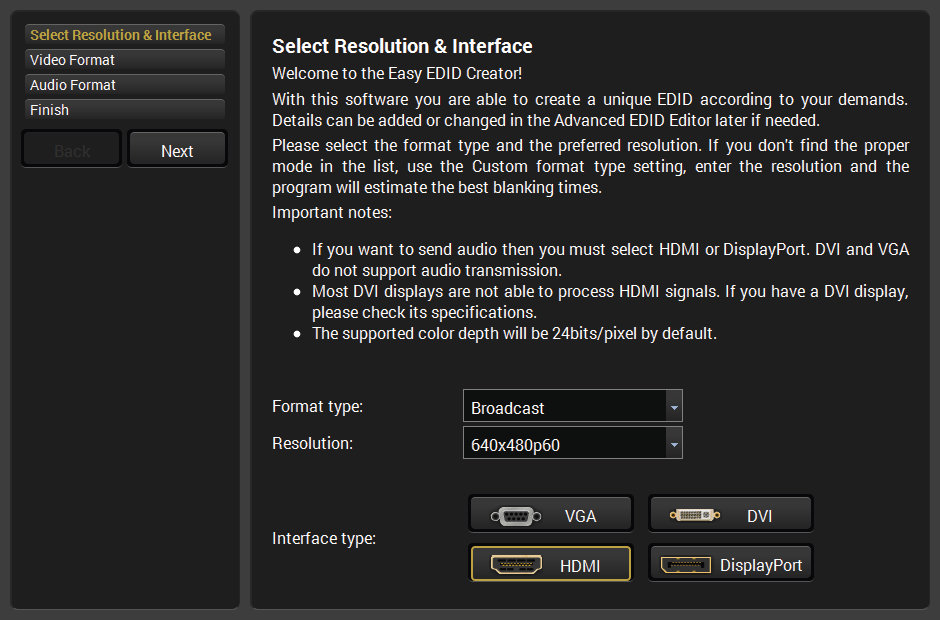
EDID Creator window
8.14.4. EDID Summary Window

Select an EDID from the Source panel and press the Info button to display EDID summary.
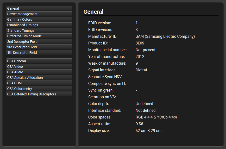
EDID summary window
The Ethernet control ports, the RS-232 port and the Infrared ports can be configured in the Control menu.
Clicking on the Ethernet port icon results opening the Port properties. The most important information and settings are available on the panel. #ethernet #tag
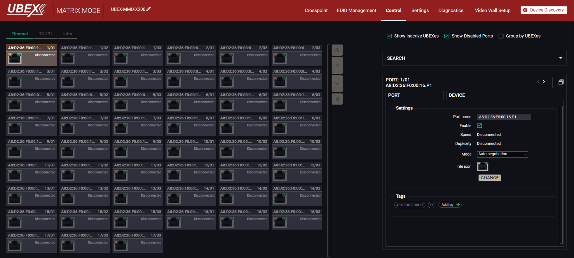
Ethernet tab in the Control menu
Switchers
▪Show Inactive UBEXes: when it is enabled, the inactive endpoints appear in the list.
▪Show Disabled Ports: when it is enabled, the disabled ports appear in the list.
▪Group by UBEXes: when it is enabled, the ports belonging to one endpoint device are arranged to one group for the better overseeing.
Available settings and tools
▪Port naming;
▪Enable/disable the port;
▪Mode (Auto negotiation / 10Mbps half-duplex / 10Mbps full-duplex / 100Mbps half-duplex / 100Mbps full-duplex / 1000Mbps full-duplex).
▪Reloading factory default settings for the selected port.
▪Tile icon: choose an icon which is the most suitable with the device connected to the endpoint.
▪Tags: unique and configurable tags can be attached to the stream for the best identification. The tags are searchable in the Search Field.
DIFFERENCE:Only the UBEX-PRO20-HDMI-F110, -F111, -F120, -F121 and F130 models are built with serial interface port.
Clicking on the RS-232 port icon results opening the Port properties. The most important information and settings are available on the panel. #rs232 #rs-232 #serial #tag
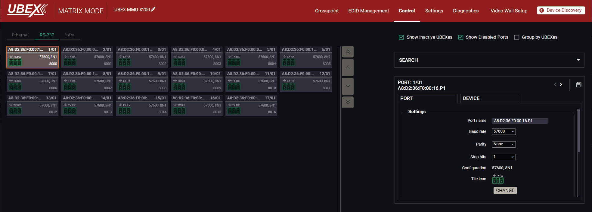
RS-232 tab in the Control menu
Switchers
▪Show Inactive UBEXes: when it is enabled, the inactive endpoints appear in the list.
▪Show Disabled Ports: when it is enabled, the disabled ports appear in the list.
▪Group by UBEXes: when it is enabled, the ports belonging to one endpoint device are arranged to one group for the better overseeing.
Available settings and tools
▪Port naming;
▪Baud rate (4800 / 7200 / 9600 / 14400 / 19200 / 38400 / 57600 / 115200);
▪Databits (read-only parameter, the value is 8);
▪Parity (None / Odd / Even);
▪Stop bits (1 / 1.5 / 2);
▪Tile icon: choose an icon which is the most suitable with the device connected to the endpoint.
▪Tags: unique and configurable tags can be attached to the stream for the best identification. The tags are searchable in the Search Field.
▪Enable command injection (enable / disable);
▪TCP port number;
▪Send message field;
▪Reloading factory default settings for the selected port.
Sending Message via RS-232 Interface

The Send message is for sending a command message in ASCII-format. This method allows escaping the control characters. #message
Escaping the Control Characters
DEFINITION:An escape sequence is a sequence of characters that does not represent itself when used inside a character or string literal, but is translated into another character or a sequence of characters.
The message can contain characters that are used as control characters in the protocol. They must be escaped. The escape character is the backslash (‘\’), and escaping means injecting a backslash before the given character (like in C language).
Control characters are the followings: \ { } # % ( ) \r \n \t
A typical usage when a message is sent and it contains such a character that must be escaped.
Example
The original message: Set(01)
The escaped message: Set\(01\)
The case above is a typical example: the UBEX endpoint device is directed to send out a message over one of its ports. The round brackets in the message are escaped.
Hexadecimal codes can be inserted in the ASCII message when using:
Message: C00\x0D
▪C00: the message.
▪\x: indicates that the following is a hexadecimal code.
▪0D: the hexadecimal code (Carriage Return).
See more serial message sending methods using LW3 protocol commands in the Sending a Text (ASCII-format) via Serial Port, Sending a Binary Message (HEX-format) via Serial Port, and the Sending a Message (ASCII-format) via Serial Port sections.
DIFFERENCE:Only the UBEX-PRO20-HDMI-F110 and F120 models are built with Infrared interface ports.
Clicking on an Infra port icon results opening the Port properties. The most important settings are available on the panel. #infra #ir #message
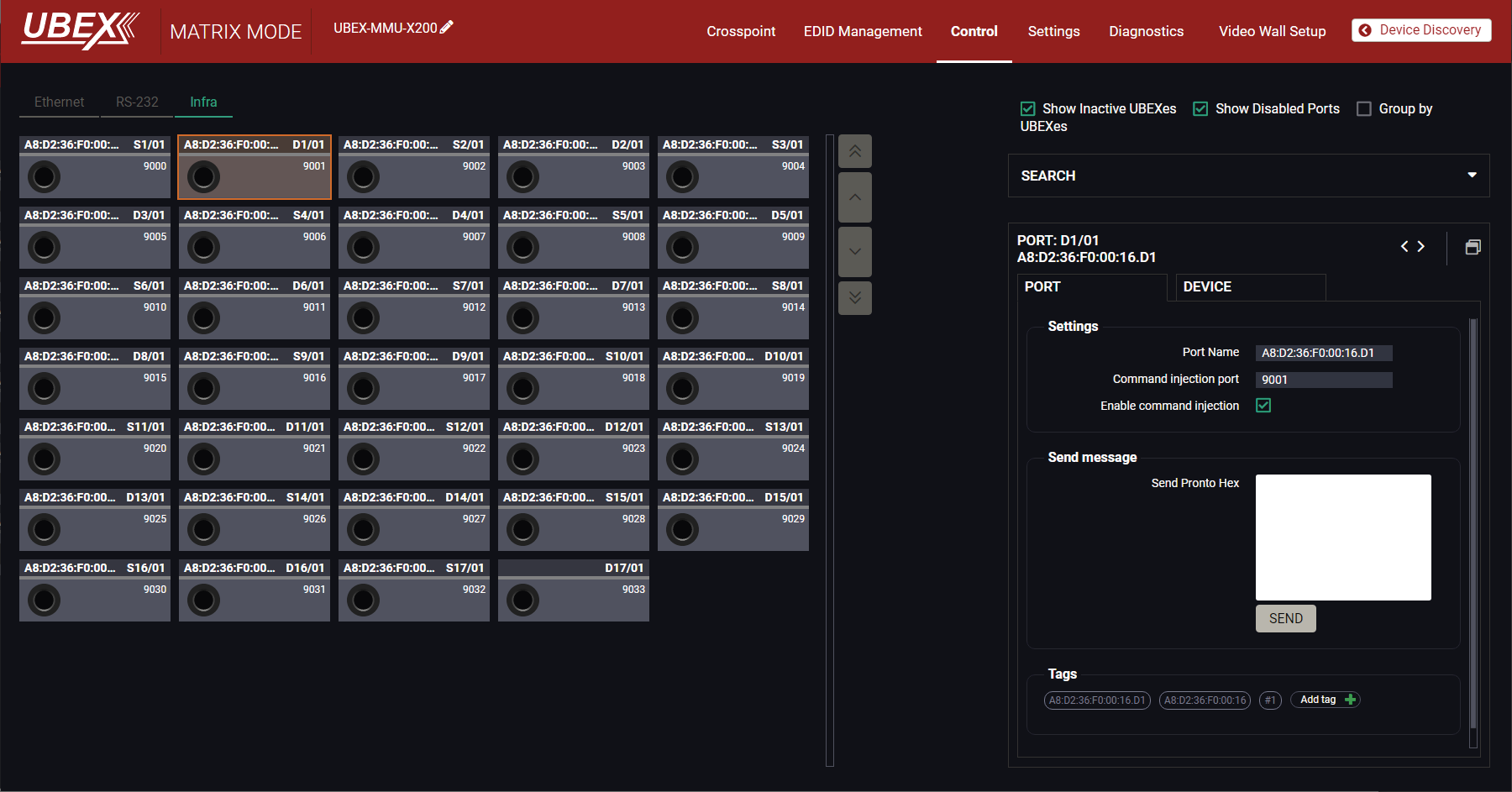
Infra tab in the Control menu
Available settings and tools:
▪Port naming;
▪Enable/disable the port;
▪Command injection port;
▪Enable command Injection (enable / disable);
▪Send message (for IR out ports only): sending pronto hex message in little-endian format on the Infra output port.
ATTENTION!The device has no built-in Infrared receiver and transmitter. For the complete usage, attach an IR emitter unit to the IR OUT and an IR detector unit to the IR IN connectors.
INFO:You can send pronto hex message in big-endian format as well, using LW3 protocol command. See the details in the Sending Hex Codes in Big-endian Format via IR Port section.
Clicking on the Settings / Device map submenu opens the Device map function window. The order list of the discovered transmitters and receivers can be changed to a custom list. The new order is saved in the MMU, the last applied order list will be loaded next time in the case of restarting the matrix. #devicemap
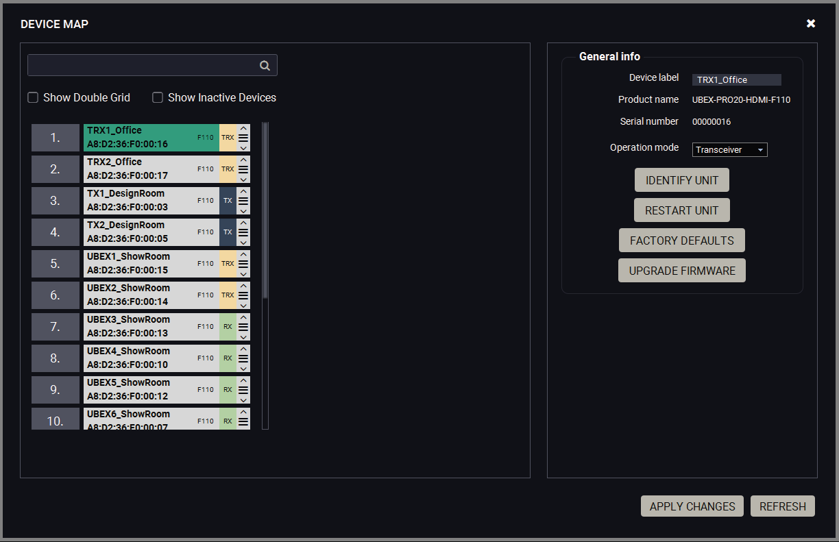
Device map window
Switchers
▪Show Double Grid: when it is enabled, the device list is duplicated for the better overseeing.
▪Show Inactive Devices: when it is enabled, the currently inactive endpoints appear in the list.
8.16.1. The Steps of the Reorder
TIPS AND TRICKS:It is recommended to change the name of the devices to unique ones before the re-order process, it can help a lot to find the desired device in the matrix. See the details about the device renaming in the Device Information section for the source side and the Device Information section for the Destination side.
Step 1.Select the tile of the desired endpoint device by clicking with the left button of the mouse.
Step 2.Drag and drop the tile to the desired place.
Step 3.Select the Apply Changes button and confirm the selection.
TIPS AND TRICKS:You can use the Identify unit button to find the selected endpoint physically. The feature makes the four front panel LEDs blink in green for 10 seconds.
Searching a Device
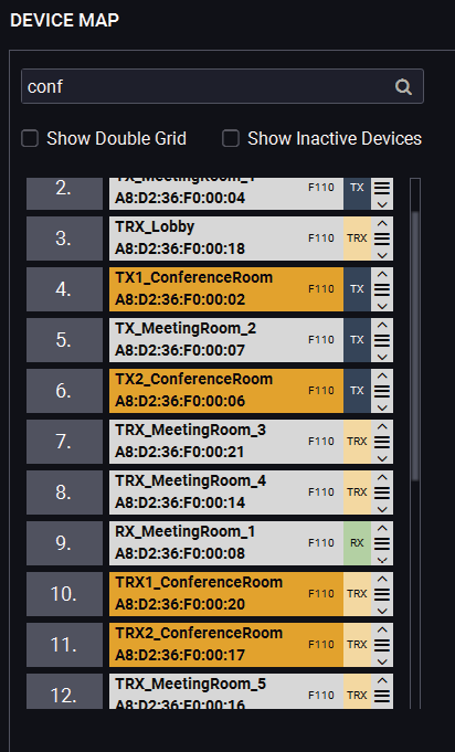
TIPS AND TRICKS:It is recommended to change the name of the devices to unique ones before the searching, it can help a lot to find the desired device in the matrix. See the details about the device renaming in the Device Information section for the source side and the Device Information section for the Destination side.
The endpoint devices can be searched in the device map list. Click in the search field and type the device name. The tiles with the matching names will be highlighted with orange. #search
8.16.2. Tools in the Device Map
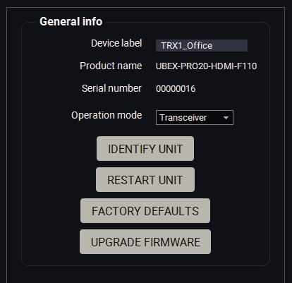
Operation Mode Changing
The operation mode (transmitter / receiver / transceiver) can be changed in the device map window. #operationmode #transmitter #receiver #transceiver #tx #rx #trx
Step 1.Select the tile of the desired endpoint device by clicking with the left button of the mouse.
Step 2.Select the desired operation mode (transmitter / receiver / transceiver) in the General info / Operation mode menu.
Step 3.Select the Apply Changes button and confirm the selection.
Step 4.The change will be applied after rebooting the endpoint.
ATTENTION!This operation always requires rebooting the endpoint device.
ATTENTION!Always check the cabling of the HDMI input / output ports before changing of the operation mode.
Identify Unit
Clicking on the button makes the four front panel LEDs blink in green for 10 seconds. The feature helps to identify the device itself in the rack shelf or on the desk. #identifyme
Restart Unit
Clicking on the button makes restarting the selected endpoint device (the same method as unplugging and reconnecting the power source). #restart #reboot
Factory Defaults
Factory defaults settings of the MMU can be recalled with a dedicated button. See the factory default values in the UBEX-MMU-X200 section. #factory
Update Firmware
See more details about it in the Update Firmware section.
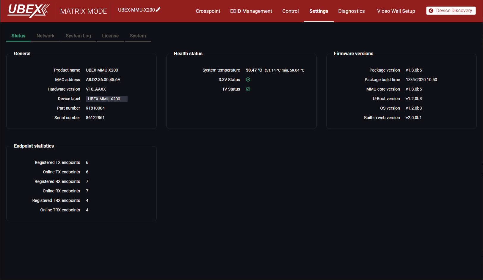
Status tab in the MMU settings menu
The most important hardware and software related information can be found on this tab: hardware and firmware version, serial numbers, endpoint statistics, temperatures, operation time, and voltage information. Device label can be changed to unique description. #status #firmwareversion #label #devicelabel
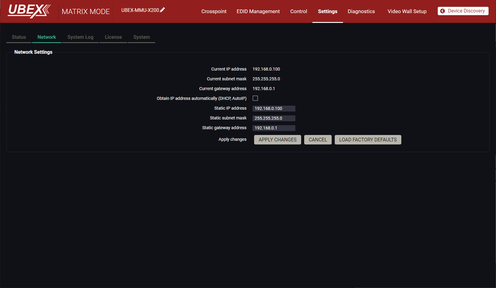
Network tab in MMU settings menu
Static IP address and DHCP (dynamic IP address) settings can be set on this tab. Always press the Apply settings button to save changes.
Factory defaults settings of the MMU can be recalled with a dedicated button. See the factory default values in the UBEX-MMU-X200 section. #network #dhcp #ipaddress
8.17.3. System Log Tab
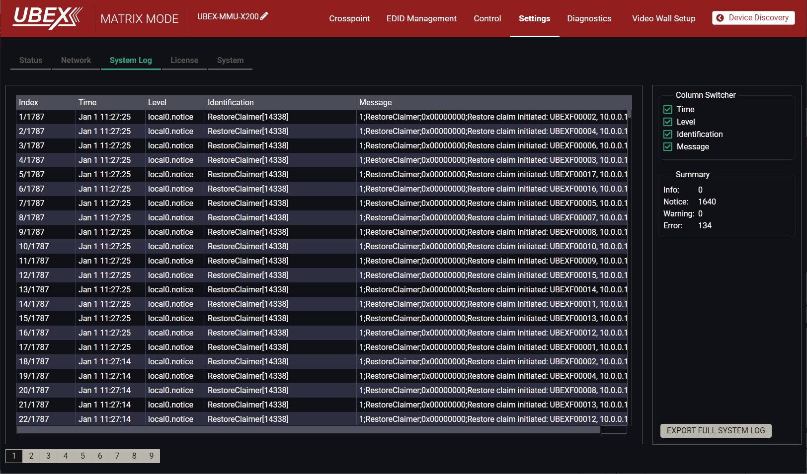
System log tab in the MMU settings menu
All UBEX matrix related notifications are listed in the System log tab which are grouped in four categories: info, notice, warning, and error. The categories are summerized on the right side of the tab in the Summary section. The list can be costumized by the Column Switchers by turning on or off the following columns: Time, Level, Identification, and Message.
All system log tracks can be saved to the control computer with the Export full system log button. #log
INFO:Please always download the system logs and send to the Lightware Support Team (support@lightware.com) for the most effective collaboration in the case of a troubleshooting issue.
DIFFERENCE:License handling is available for MMU part number 91810015 and from firmware version v1.7.0 only. #license
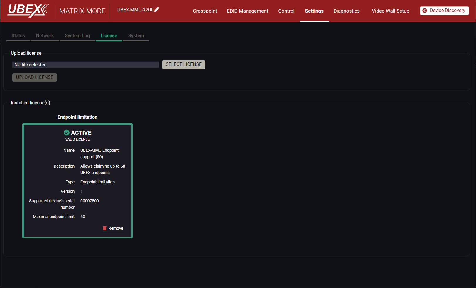
License tab in the MMU settings menu
The Matrix Management Unit can claim up to 16 endpoint devices by default. The number of claimable endpoints can be expanded by endpoint license. See more details about license types in the Endpoint License section.
The License tab shows the details and status of the active license of the MMU and provides interface managing the endpoint licenses.
Uploading of a License
When a new endpoint license is purchased for the MMU, Lightware sends an encrypted file which makes avaliable to extend your UBEX matrix. To activate the license, please follow the steps:
Step 1.Click on the Select License button.
Step 2.Browse the license file what you received from Lightware.
Step 3.Confirm the license choice by clicking on the OK button.
ATTENTION!The MMU must apply a quick reset to complete applying of the new license.
Step 4.Confirm to restart the MMU to apply the new license.
Step 5.After the device reboots, the new license is actived on the MMU and ready to claim new endpoint devices on the network.
Removing the License
ATTENTION!When an active license is applied in the Matrix Management Unit, it must be removed before a new license is uploaded.
Step 1.Click on the Remove button.
Step 2.Confirm your choice by clicking on the OK button.
ATTENTION!The MMU must apply a quick reset to complete the removing process.
Step 3.Confirm to restart the MMU to apply the new setting.
Troubleshooting
If you experience any problem with the endpoint license handling of the MMU, please read the possible root causes in the Use Cases section.
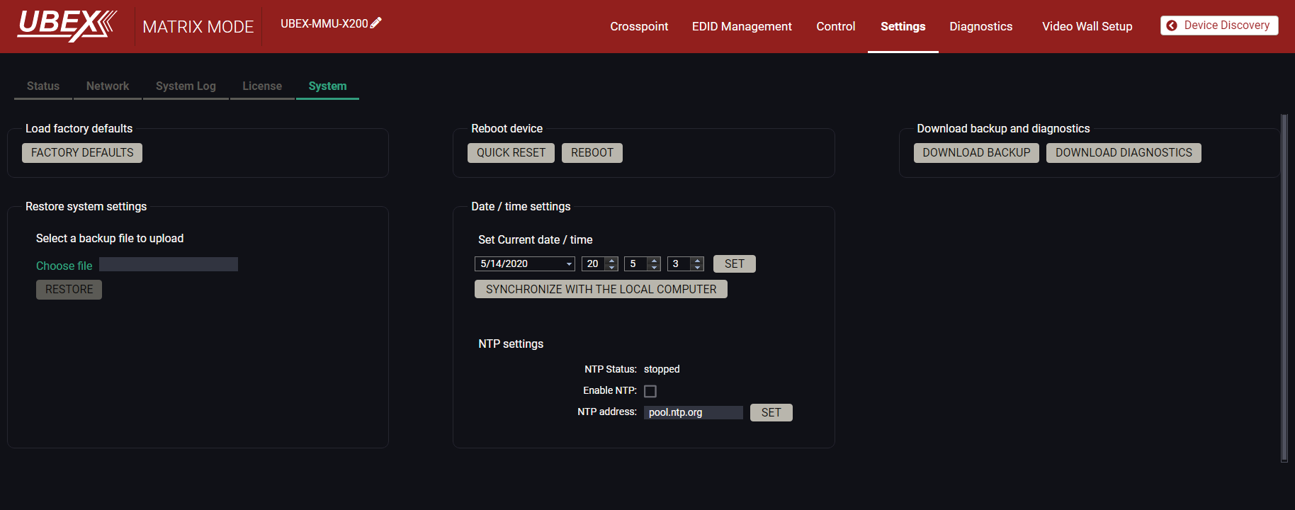
System tab in the MMU settings menu
The following functions are available under System tab:
▪Factory defaults - recalling factory defaults settings and values for the MMU. All factory default settings are listed in the UBEX-MMU-X200 section. #factory
▪Download backup and diagnostics - saving the configuration backup file and the diagnostic information of the device. See the contents of the backup file in the Content of Backup File section. #backup
▪Reboot device
=Quick reset: the controller software of the MMU reboots, but the hardware of the unit does not reboot. #softreset
=Reboot: the MMU reboots, it is the same like disconnecting the power source and reconnecting again. #reboot #restart #reset
INFO:The video signal transmission is not affected by any kind of rebooting of the MMU.
▪Restore system settings - select a backup file of the MMU on your computer and select the Restore button to load it. The configuration settings saved in the file are applied immediately.
▪Date / time settings - two options are available to set the date and time:
=Set current date / time - system time can be set manually or can be synchronized with your control device. #time #date
=NTP settings: an NTP server address can be set and enable/disable the service to synchronize the date and time. #ntp
DEFINITION:The Network Time Protocol (NTP) is a networking protocol for clock synchronization between computer systems over packet-switched, variable-latency data networks.
8.18. Diagnostics Menu
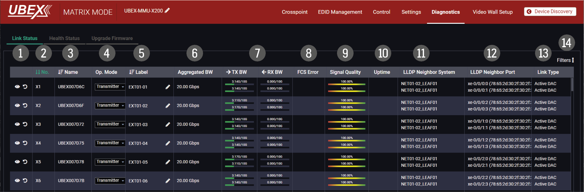
Link Status tab in the Diagnostics menu
The actual link, connection and signal bandwidth status of the UBEX matrix can be overviewed in the Link Status tab. The details of the listed information are the following: #systemmonitor #uplink #link #sfp
|
1 |
Action buttons |
|
Identify the device: clicking on the icon makes the four front panel LEDs blink in green for 10 seconds. The feature helps to identify the device itself in the rack shelf. |
||||
|
|
Restart the device: clicking on the icon makes restarting the endpoint. |
||||||
|
2 |
Logical device ID (endpoint number) |
Logical device ID means the MMU assigns a number to the endpoints ordered by the discovery. For example the first endpoint gets the 1 (appears as X1), the second one the 2 (appears as X2). The listed endpoint devices can be sorted by clicking on the icon. |
|||||
|
3 |
Device name |
The name of device which is composed of the UBEX word and the last six characters of the MAC address. The listed endpoint devices can be sorted by clicking on the icon. |
|||||
|
4 |
Operation Mode |
The current operation mode of the endpoint device (transmitter / receiver / transceiver). The operation mode can be changed in the drop-down menu. This operation requires restarting the device. |
|||||
|
5 |
Label |
The device label of the endpoint. It can be changed by clicking on the icon. See the details in the Device Information section in case of the TX or TRX operation modes and in the Device Information section in case of RX or TRX operation modes. The listed endpoint devices can be sorted by clicking on the icon. |
|||||
|
6 |
Aggregated BW |
The aggregated bandwidth which are used by the endpoint device. It can be 10.00 Gbps (in case of only one SFP+ port is used) or 20.00 Gbps (in case of both SFP+ ports are used). |
|||||
|
7 |
Load Balancing Graphics |
TX BW |
RX BW |
||||
|
The current bandwidth of the transmitted AV signal grouped by the SFP+ ports. |
The current bandwidth of the received AV signal grouped by the SFP+ ports. |
||||||
|
Failure Icons |
|||||||
|
OFFLINE |
Cables are disconnected or both are in wrong LAG. |
||||||
|
|
|
Cable is in wrong LAG. |
|||||
|
|
|
Cable is disconnected on endpoint or switch side. |
|||||
|
|
SFP+ module is disconnected on endpoint side. |
||||||
|
8 |
FCS Error |
Frame check sequence error. If the icon appears, there are FCS errors in the connection, moving cursor over the icon shows the actual packet error number. See possible solutions for the problem in the Troubleshooting chapter. |
|||||
|
9 |
Signal Quality |
The meter shows the current signal quality in percent. |
|||||
|
q |
Uptime |
Uptime of the link connection. |
|||||
|
w |
LLDP Neighbor System |
The type of the L3 network switch where the endpoint device is connected to. |
|||||
|
e |
LLDP Neighbor Port |
The ID number and the MAC address of the port in the network switch. |
|||||
|
r |
Link Type |
The SFP+ interface between the endpoint and the network switch. |
|||||
|
t |
Filters |
Applying filters help to find the required endpoint devices for checking in case of a larger UBEX matrix. The function contains the following filter categories: |
|||||
|
▪Operation Mode –Transmitters –Receivers –Transceivers ▪Aggregated Bandwidth –Offline –10G –20G ▪FCS Errors –FCS Errors –No FCS Errors |
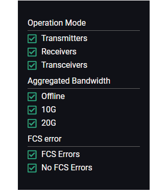
|
||||||
INFO:See more practical troubleshooting use cases in the Network Diagnostics for UBEX Matrix section.
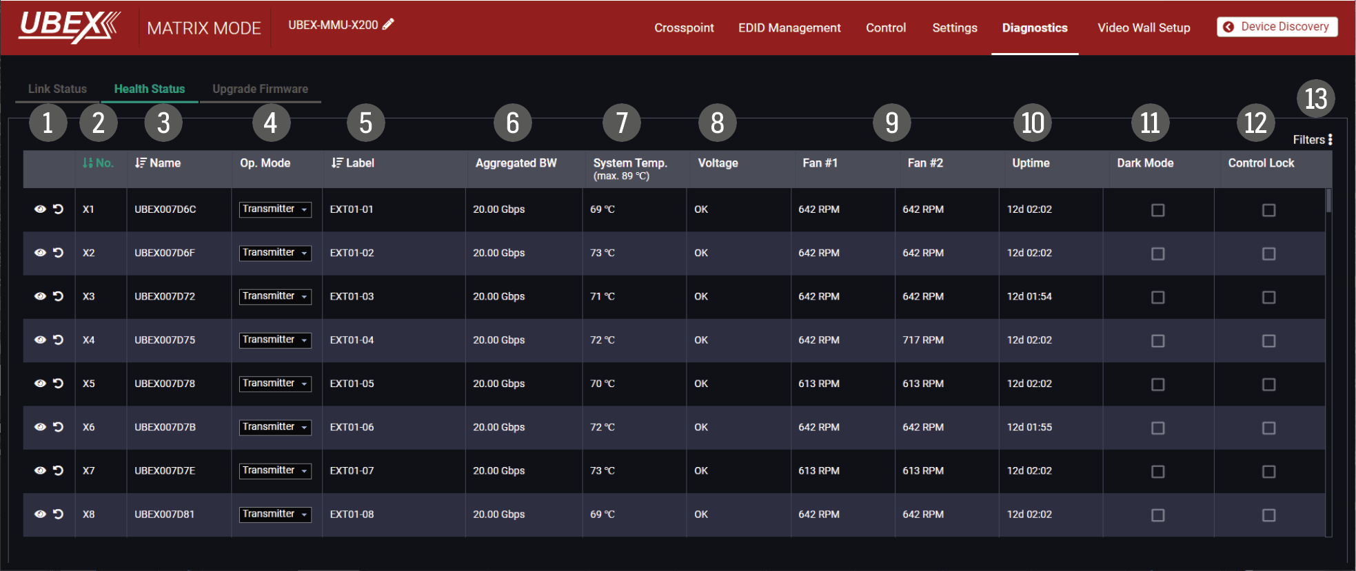
Health Status tab in the Diagnostics menu
The actual temperature, voltage, fan, dark mode and control lock status of the endpoint devices can be overviewed in the Link Status tab. The details of the listed information are the following: #systemmonitor #darkmode #controllock #health
|
1 |
Action buttons |
|
Identify the device: clicking on the icon makes the four front panel LEDs blink in green for 10 seconds. The feature helps to identify the device itself in the rack shelf. |
|
|
|
Restart the device: clicking on the icon makes restarting the endpoint. |
|||
|
2 |
Logical device ID (endpoint number) |
Logical device ID means the MMU assigns a number to the endpoints ordered by the discovery. For example the first endpoint gets the 1 (appears as X1), the second one the 2 (appears as X2). The listed endpoint devices can be sorted by clicking on the icon. |
||
|
3 |
Device name |
The name of device which is composed of the UBEX word and the last six characters of the MAC address. The listed endpoint devices can be sorted by clicking on the icon. |
||
|
4 |
Operation Mode |
The current operation mode of the endpoint device (transmitter / receiver / transceiver). The operation mode can be changed in the drop-down menu. This operation requires restarting the device. |
||
|
5 |
Label |
The device label. It can be changed by the user. See the details in the Device Information section in case of the TX or TRX operation modes and in the Device Information section in case of RX or TRX operation modes. The listed endpoint devices can be sorted by clicking on the icon. |
||
|
6 |
Aggregated BW |
The aggregated bandwidth which are used by the endpoint device. It can be 10.00 Gbps (in case of only one SFP+ port is used) or 20.00 Gbps (in case of both SFP+ ports are used). |
||
|
7 |
System Temperature |
System temperature of the endpoint device displayed in Celsius degrees. The values are the following: ▪Under 84 °C - OK ▪Between 85 °C and 89 °C - Warning ▪Above 90 °C - Error |
||
|
8 |
Voltage |
Voltage status. Three possible values can be displayed: OK; Warning; Error. In case ERROR value please power off the device immediately. |
||
|
9 |
Fan #1 / Fan #2 |
Actual RPM (revolution per minute) value of the fan #1 and #2. |
||
|
q |
Uptime |
Uptime of the endpoint device. |
||
|
w |
Dark Mode |
The dark mode feature can be enabled or disabled. It keeps the LCD screen and the LEDs unlit to hide the device during an event when the mode is enabled. |
||
|
e |
Control Lock |
Enable/disable the operation of the jog dial control knob. |
||
|
r |
Filters |
Applying filters help to find the required endpoint devices for checking in case of a larger UBEX matrix. The function contains the following filter categories: |
||
|
▪Operation Mode –Transmitters –Receivers –Transceivers ▪Aggregated Bandwidth –Offline –10G –20G |
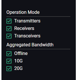
|
|||
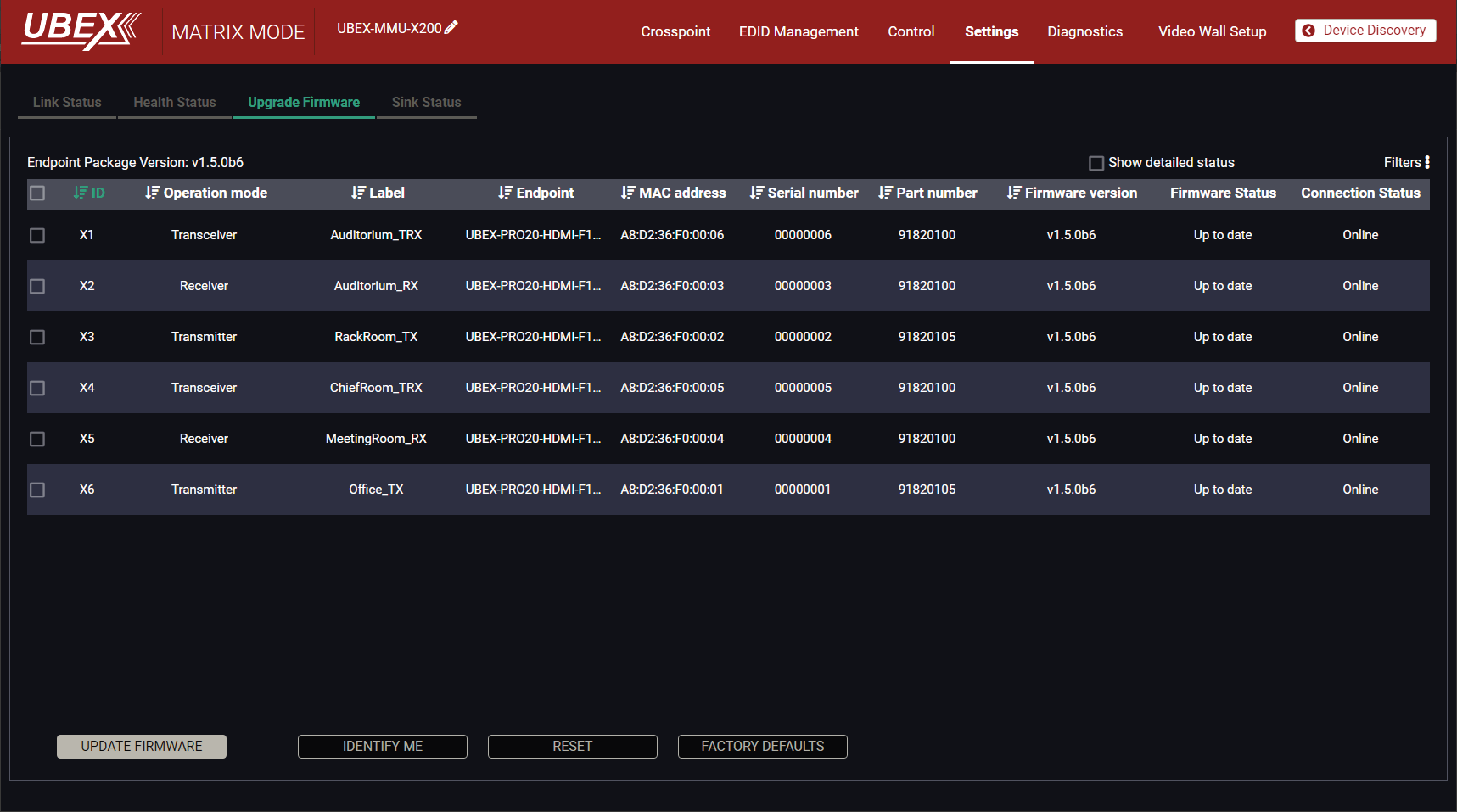
Update firmware tab in the Settings menu
The centralized firmware update method for the connected endpoint devices is the most comfortable way to keep your devices up to date. The selected units can be updated together, the procedure is supervised by the MMU, no user interaction is needed. During the firmware update, the AV transmission continues smoothly in the unselected endpoint devices.
ATTENTION!The centralized firmware update feature is working from the installed MMU firmware v1.1.0 and endpoint firmware v1.3.1 and available for the later firmware package versions. The endpoint firmware packages till v1.3.1 can be installed with LDU2 software - see the details in the Endpoint Update - Manual Method section.
DIFFERENCE:Lightware highly recommends using the same and cohesive firmware versions on the UBEX extenders and the MMU. Connection between extenders installed with different versions might cause unexpected performance failures. See the list of cohesive endpoint and MMU firmware versions in the Endpoint Firmware Packages in the MMU section.
See the details about this feature and the steps of the update in the Endpoint Update - Centralized Firmware Update section.
8.18.4. Sink Status Tab
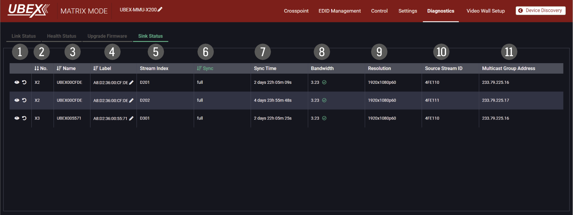
Sink status tab in the Settings menu
The stream index, actual bandwidth, resolution and the multicast group address of the destination stream can be overviewed in the Sink Status tab. The details of the listed information are the following: #systemmonitor #health
|
1 |
Action buttons |
|
Identify the device: clicking on the icon makes the four front panel LEDs blink in green for 10 seconds. The feature helps to identify the device itself in the rack shelf. |
|
|
Restart the device: clicking on the icon makes restarting the endpoint. |
||
|
2 |
Logical device ID (endpoint number) |
Logical device ID means the MMU assigns a number to the endpoints ordered by the discovery. For example the first endpoint gets the 1 (appears as X1), the second one the 2 (appears as X2). The listed endpoint devices can be sorted by clicking on the icon. |
|
|
3 |
Device name |
The name of device which is composed of the UBEX word and the last six characters of the MAC address. The listed endpoint devices can be sorted by clicking on the icon. |
|
|
4 |
Label |
The device label. It can be changed by the user. See the details in the Device Information section in case of the TX or TRX operation modes and in the Device Information section in case of RX or TRX operation modes. The listed endpoint devices can be sorted by clicking on the icon. |
|
|
5 |
Stream Index |
The unique ID of each destination stream. See more details about the stream index calculation in the Endpoint Port Numbering (Stream ID Calculation) section. |
|
|
6 |
Sync |
The actual syncronization status of the destination stream. The values can be the following: ▪full - the destination stream is fully syncronized and transmitted to the sink device. ▪partial - the destination stream is syncronized partially only. The root cause could be a network error (e.g. IP package loss). ▪nosync - the destination stream is disconnected to the endpoint device. |
|
|
7 |
Sync Time |
The time since the full syncronization. |
|
|
8 |
Bandwidth |
The actual bandwidth of the destination stream. |
|
|
9 |
Resolution |
The resolution of the destination stream. |
|
|
q |
Source Stream ID |
A unique stream ID which is generated in transmitter and sent to the receiver. It cannot be changed by the user. |
|
|
w |
Multicast Group Address |
The multicast group address of the destination stream. Only for debugging purpose. |
|
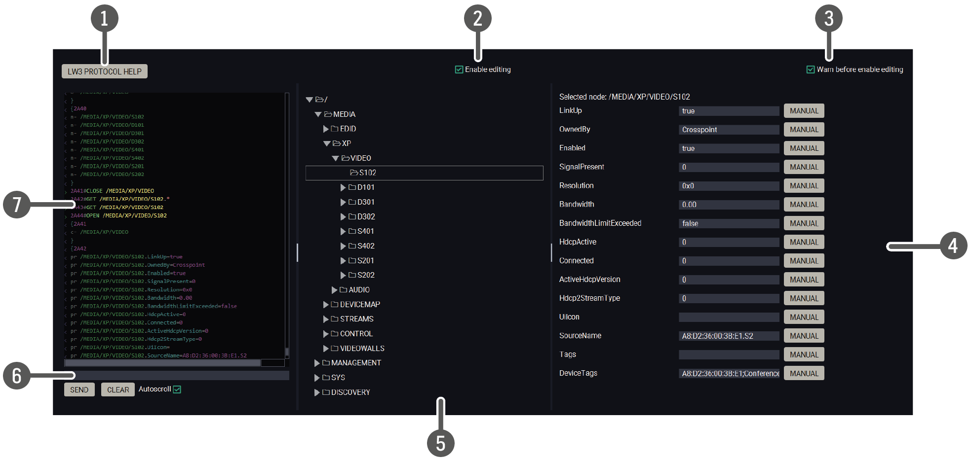
Select the Settings / Terminal menu to open the Terminal window. #terminal #advancedview
|
1 |
LW3 protocol help |
Pushing the button results in a help window opening which, describes the most important information about LW3 protocol commands in HTML format. |
|
|
2 |
Edit mode |
The default appearance is the read-only mode. If you want to modify the values or parameters, tick the option. You will be prompted to confirm your selection. |
|
|
3 |
Warning mode |
If this is checked, a warning window pops up when you enable Edit mode. |
|
|
4 |
Node list |
Correspondent parameters and nodes are shown that are connected to the selected item in the protocol tree. |
|
|
Manual button: |
Manual (short description) of the node can be called and displayed in the terminal window. |
||
|
Set button: |
Saves the value/parameter typed in the textbox. |
||
|
Call button: |
Calls the method, e.g. reloads factory default settings. |
||
|
5 |
Protocol tree |
LW3 protocol tree; select an item to see its content. |
|
|
6 |
Command line |
Type the desired command and execute it by the Send button. Clear all current commands and responses in the Terminal window by the Clear button. |
|
|
7 |
Terminal window |
Commands and responses with time and date are listed in this window. Sent command starts with ‘>’ character, received response starts with ‘<’ character. The color of each item depends on the type of the command and the response. The content of the window can be emptied by the Clear button. If the Autoscroll option is ticked, the list is scrolled automatically when a new line is added. |
|
The UBEX devices can be arranged to a video wall in Matrix mode. This section is about the UBEX video wall, including a step-by-step tutorial to create a new wall, and the handling of the system in the Lightware Device Controller (LDC) software. #videowall #vw #layout #zone
8.20.1. Tutorial - Creating a New Video Wall
Navigate to the Video Wall Setup menu. The default state is the empty window (no video wall is defined).
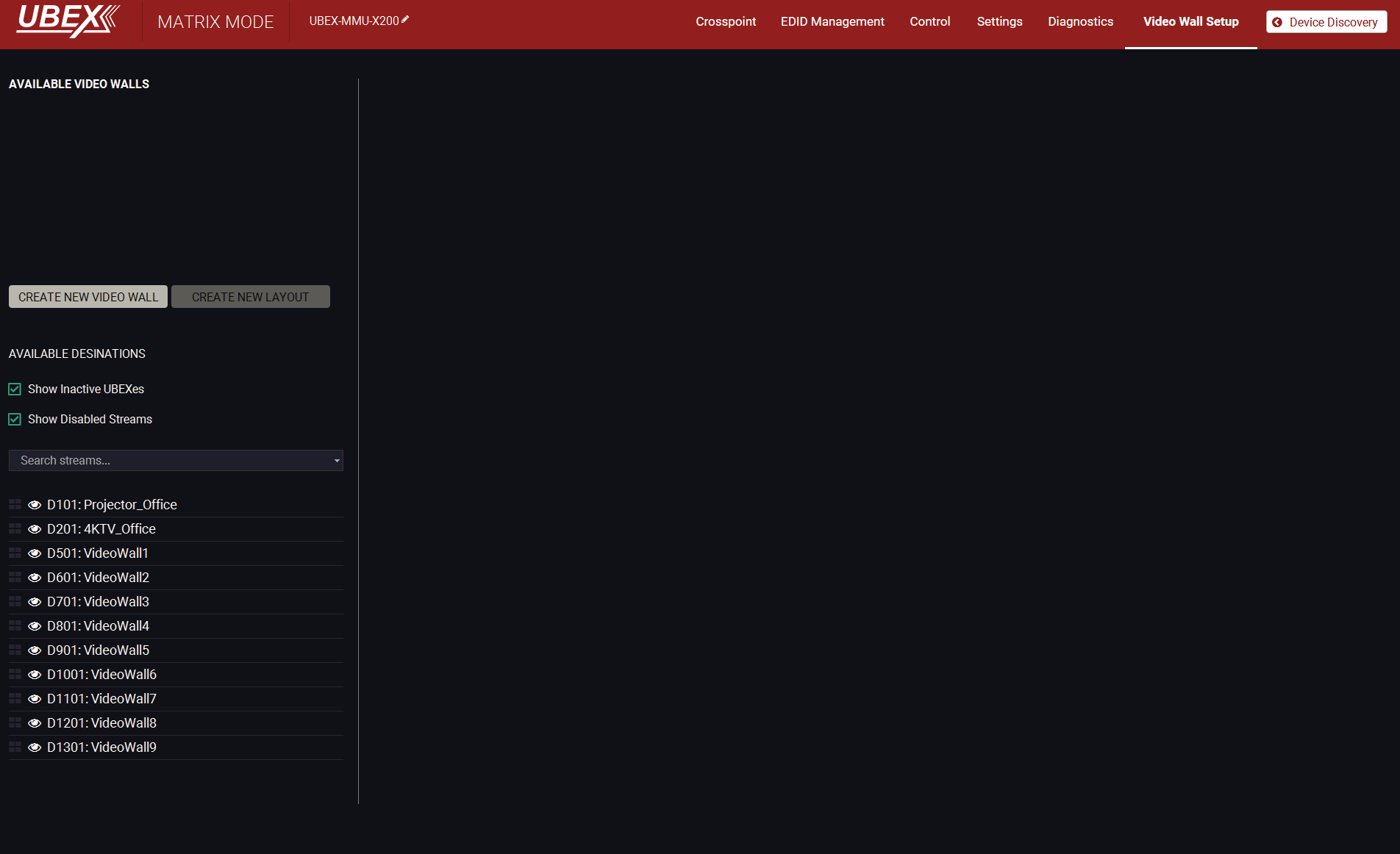
Default state of the Video wall setup menu
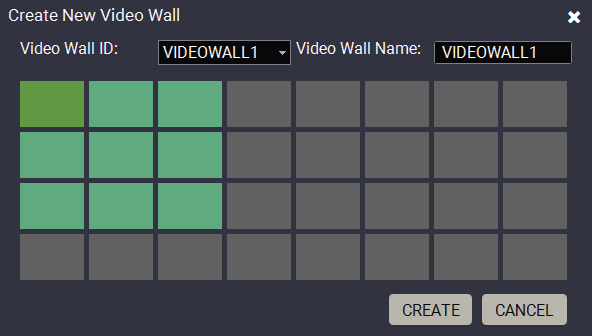
Step 1.Click on the Create New Video Wall button. A wizard pops up where you can add the size of the wall. Click on the upper left corner of the wall at first, then click on the lower right. A unique name can be added in the Video wall name field, the default for the first one is VIDEOWALL1. Click on the Create button when ready.
A 3x3 wall is created in our example.
INFO:The UBEX video wall system supports the display devices up to 8x4 (column x row).
Step 2.The next step is adding the destination devices to the wall where the content will be displayed. The available destination streams appear on the lower left side of the window. Click on a destination stream to see its tags. You can search between the destination streams using the Search streams field. The tags are also searchable. Clicking on the icon launch the Identify Stream / Identify Display feature.
Drag and drop the destination streams to assign them to the wall. If a stream has been assigned to the wall, it will disappear from the list.
The video wall size can be changed by clicking on the Change video wall size button.
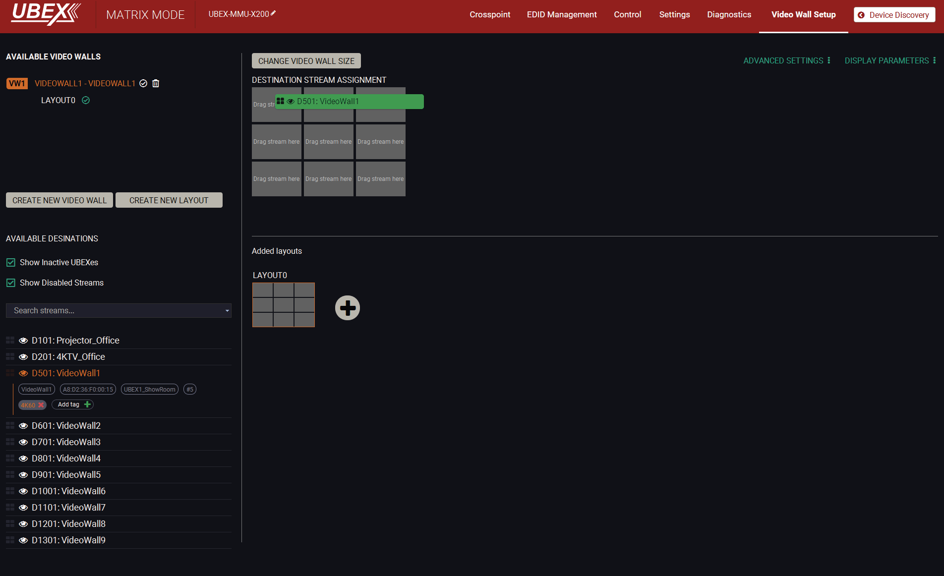
Destination stream assignment
DIFFERENCE:The receiver is built with scaler function on both HDMI output ports from firmware version v2.1.0. Both HDMI out 1 and 2 ports of the receiver can participate in the video wall.
TIPS AND TRICKS:Adding unique names and tags to the destination streams before defining the video wall makes easier the configuration steps. See the details in the Video Destination Port Properties Window section.
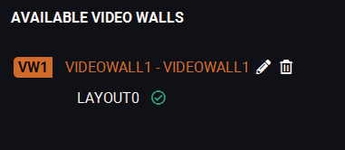
Step 3.Complete the video wall. Click in the (Activate) icon next to of the name of the video wall. When the icon changes to and the name changes to white, the video wall becomes active.
8.20.2. Advanced Settings and Display Parameters

For editing the Advanced Settings and the Display parameters, click on the (Edit) icon next to of the name of the video wall. When the icon changes to and the name changes to orange, the video wall is in edit mode.
Advanced Settings
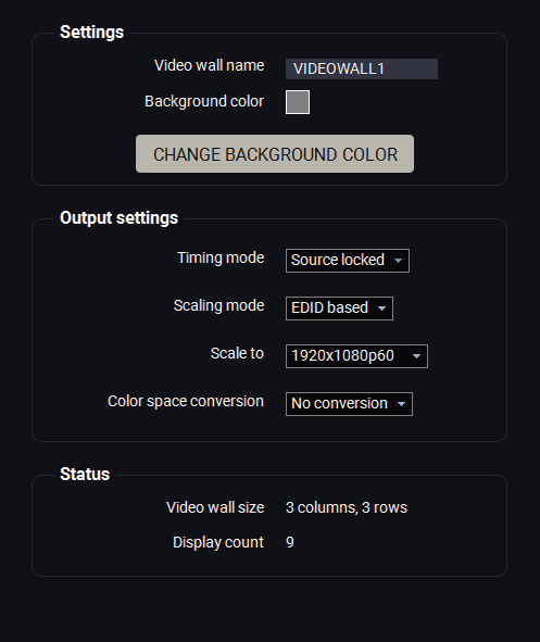
Clicking on the Advanced settings button results opening the advanced settings of the video wall.
Settings
▪Video wall name;
▪Change background color: when no zone(s) are defined for a new layout, the color which is set here will appear on the display devices. The working method is the same with the No Sync Screen (Test Pattern) function.
Output Settings
▪Timing mode (Free run / Source locked): see the more details about it in the Timing Modes section. The recommended setting is the Source locked. #timingmode #freerun #sourcelocked
▪Scaling mode: #scaler #frc
=Passthrough: the scaler is in pass-through mode.
=Forced resolution: the scaling is active, the selected value in the forced resolution option will be applied to the video signal;
=EDID based: the scaler forces the resolution that is read out from the EDID of the connected sink device.
▪Forced resolution: list of the available resolutions with refresh rate values. The selected one will be applied to the video signal. See the available resolutions in the Resolutions of the Scaler section.
▪Image position (Stretch / Fit / Center);
▪Color space conversion (No conversion / RGB / YCbCr 4:4:4 / YCbCr 4:2:2); #csc #colorspace
Status
▪Video wall size;
▪Display count.
Display Parameters
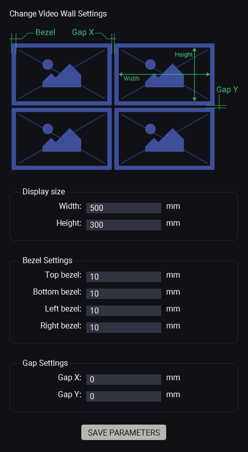
Clicking on the Display parameters button results opening the display parameter window where you can customize parameters of the display devices installed in the video wall.
Display Size
The width and the height of the display in mm.
Bezel Settings
The size of the top, bottom, left, and right bezels in mm.
Gap Settings
The size of the gap between the displays in mm.
When it is completed, click on the Save parameters button.
8.20.3. Tutorial - Defining New Layouts and Zones
More different layouts can be defined for the same video wall.
When a new video wall is created, the default layout (LAYOUT0) is also created which has only one zone (ZONE0). It contains all destination streams connected to the video wall. This section about how to create a new layout and customize it for your current installation.
Step 1.Click on the (Edit) icon next to of the name of the video wall When the icon changes to and the name changes to orange, the video wall is in edit mode.

Step 2.Click on the icon in the Added layouts section to add a new layout to the video wall. The schematic view of the video wall appears on the top.
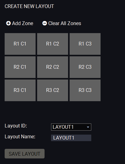
Step 3.Add a unique name for the layout in the Layout name field, the default name is LAYOUT1. The next step is defining the zones where the contents will be displayed.
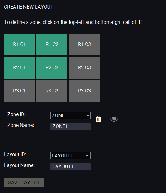
Step 4.Click on the Add Zone button. Click on the upper left corner of the zone at first, then click on the lower right. A unique name can be added in the Zone name field, the default for the first one is ZONE1.
Define all zones on the video wall. In our example three zones are created by the following way:
ZONE1: R1 C1, R1 C2, R2 C1, R2 C2;
ZONE2: R1 C3, R2 C3;
ZONE3: R3 C1, R3 C2, R3 C3.
Legend: R1 C3 = Display in the Row 1 and Column 3.
The picture below shows all the defined zones:
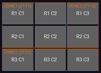
Step 5.Click on the Save layout button to complete the new layout.
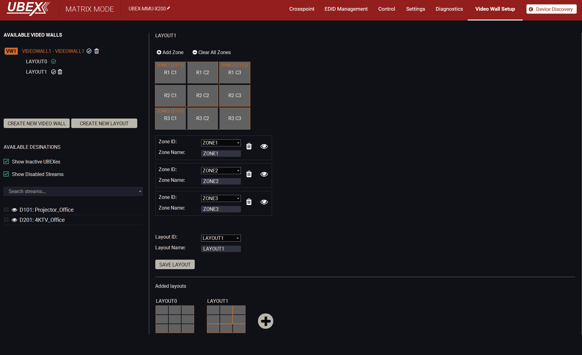
The new layout is created
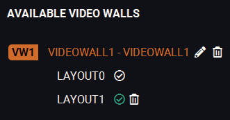
Step 6.Complete the video wall. Click on the (Activate) icon next to of the name of the video wall. When the icon changes to and the name changes to white, the video wall with the new layout becomes active.
Step 7.Click on the (Activate) icon next to of the name of the layout. The green icon means the currently active layout.
8.20.4. Managing of the Layout and Zones

The new layout can be deleted by clicking on the (Delete) icon next to the name of the layout in the Available video walls section.
All zones can be deleted by clicking on the Clear All Zones button.

Each zone can be deleted by clicking on the (Delete) icon in the zone section. in the Available video walls section.
The zone can be identified by clicking on the (Identify zone) icon. See the details about in the Identify Stream / Identify Display section.
8.20.5. Crosspoint Menu with Video Wall
Grid View
Navigate to the Crosspoint menu - Grid View to select a source stream for the video wall.
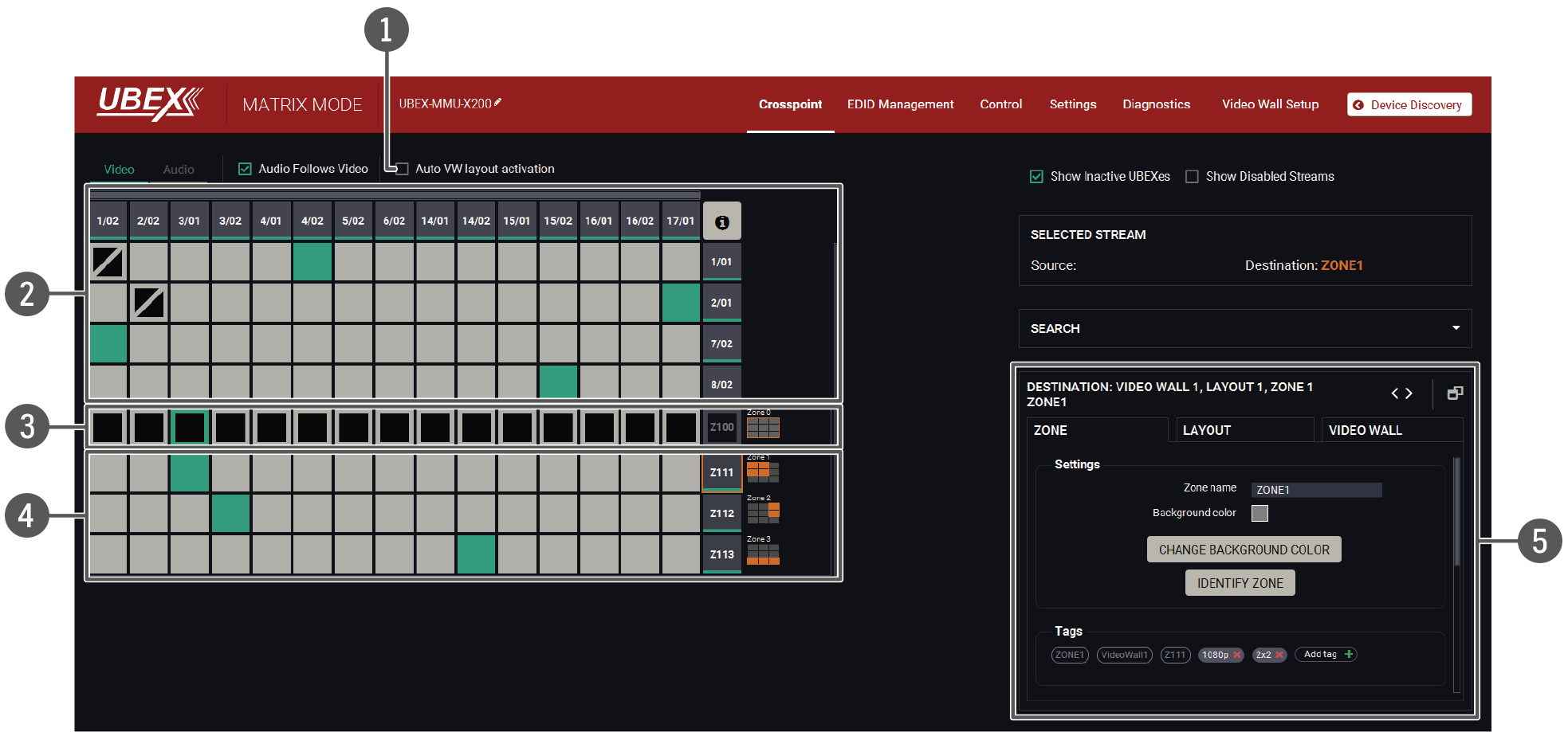
Legend of the Crosspoint Menu
|
1 |
Auto VW layout activation switcher |
The explanation of the two available options are the following: ▪Enabled: the video wall layout becomes active suddenly when the crosspoint setting is changed in it. ▪Disabled: switching of a source stream does not effect the video wall layout activation. |
|
2 |
Non-video wall area |
Source streams, destination streams, and the crosspoint connections which are not the part of the video wall. |
|
3 |
Video wall - Layout0 |
Video wall area, Layout0 (the default layout of the video wall). Clicking on the Zone tile ( on the Destination stream side) opens the Zone Properties Window on the right side. The layout is not active currently. |
|
4 |
Video wall - Layout1 |
Video wall area, Layout1 (the layout which is created by the user). Clicking on one of the Zone tiles (on the Destination stream side) opens the Zone Properties Window on the right side. This layout is the active one. |
|
5 |
Properties window |
The properties, available settings, and status information of the selected zone are displayed in this section. Three tabs are available: Zone, Layout, and Video wall. Clicking on the icon the properties section opens in new window. |
Tile View
Navigate to the Crosspoint menu - Tile View to select a source stream for the video wall.
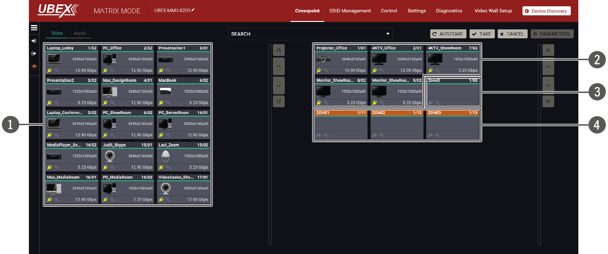
Legend of the Crosspoint Menu
|
1 |
Source streams |
Each tile represents a stream coming from one of the input ports of the transmitter or transceiver. Each of them can be selected as a video source for one of the video wall zones. |
|
2 |
Destination streams - non-video wall area |
Destination streams which are not the part of the video wall. |
|
3 |
Video wall - Layout0 |
Video wall area, Layout0 (the default layout of the video wall). Selecting the Zone tile and clicking to the Parameters button opens the Zone Properties Window. The layout is not active currently. |
|
4 |
Video wall - Layout1 |
Video wall area, Layout1 (the layout which is created by the user). Selecting one of the Zone tiles and clicking to the Parameters button opens the Zone Properties Window. This layout is the active one (highlighted with orange). |
See the detailed information about the tile view of the crosspoint in the Tile View section. #switch #crosspoint
8.20.6. Zone Properties Window
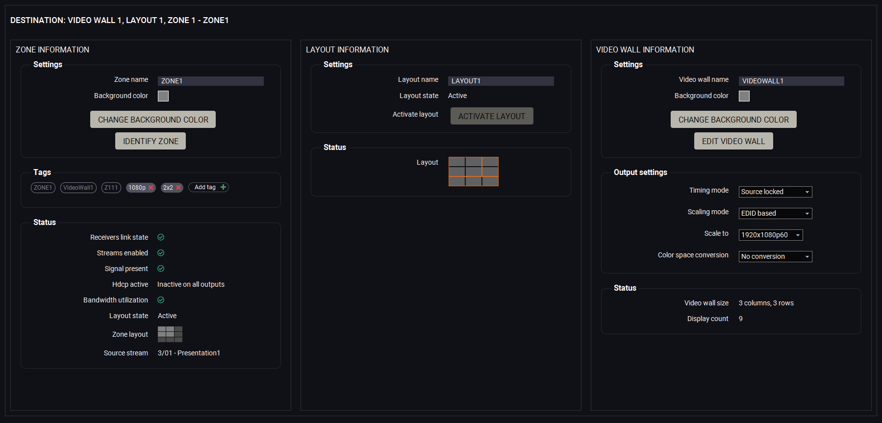
Zone properties window
Zone Information
The most important information and settings of the stream are available in the Zone information section.
Settings
▪Zone naming;
▪Change background color: when no signal / no source stream is set for the zone, the color which is set here will appear on the display devices. The working method is the same with the No Sync Screen (Test Pattern) function.
▪Identify Zone: see the details about this feature in the Identify Stream / Identify Display section.
Tags
Unique and configurable tags can be attached to the stream for the best identification. The tags are searchable in the Search Field. #tag
Status
All important information (streams enabled, signal present, HDCP status e.g.) are available in the status section. The Zone layout and the Source stream are also can be checked in this panel.
Layout Information
The most important information and settings of the input port are available in the Port information section.
Settings
▪Zone naming;
▪Layout state (active / inactive);
▪Activate layout: clicking on the button makes the current layout to active on the video wall;
Status
▪Layout drawing.
Video Wall Information
Settings
▪Video wall naming;
▪Change background color: when no signal / no source stream is set for the video wall, the color which is set here will appear on the display devices. The working method is the same with the No Sync Screen (Test Pattern) function.
▪Identify Zone: see the details about this feature in the Identify Stream / Identify Display section.
Output Settings
▪Timing mode (Free run / Source locked): see more details about it in the Timing Modes section. #timingmode #freerun #sourcelocked
▪Scaling mode: #scaler #frc
=Passthrough: the scaler is in pass-through mode.
=Forced resolution: the scaling is active, the selected value in the forced resolution option will be applied to the video signal;
=EDID based: the scaler forces the resolution that is read out from the EDID of the connected sink device.
▪Scale to: list of the available resolutions with refresh rate values. The selected one will be applied to the video signal. See the available resolutions in the Resolutions of the Scaler section.
▪Color space conversion (No conversion / RGB / YCbCr 4:4:4 / YCbCr 4:2:2); #csc #colorspace
Status
▪Video wall size;
▪Display count.
8.21. Multiviewer Configuration
DIFFERENCE:The fully operational multiviewer operation mode with GUI and centralized fimware update support is available from endpoint firmware package v3.5.1 and MMU firmware package v2.4.3. #multiviewer #new
UBEX multiviewer is a special operation mode of the endpoint device where video signals from different sources can be displayed on one single sink device ordered in various layouts. Learn more details about the available features and options in the Multiviewer Mode section.
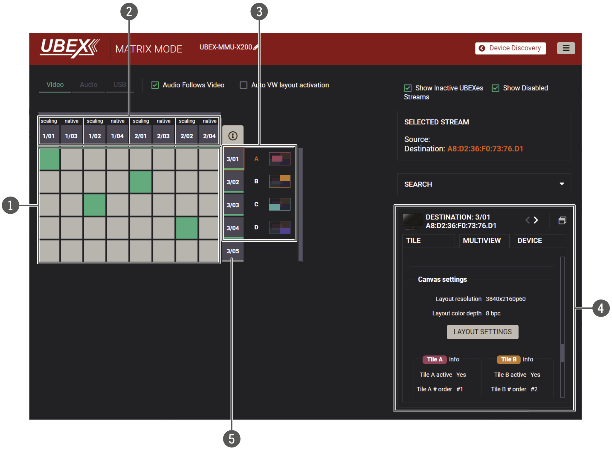
Legend of the Crosspoint Menu
|
1 |
Crosspoint table |
The sources of the multiviewer tiles can be selected in the crosspoint table. The green box means the connection is established. The legend of the connection and stream tiles is available in the crosspoint table by selecting the button. |
|
|
2 |
Source streams |
Based on the Multistream Feature of the Transmitter, two streams are available for each source port: ▪scaling - this stream can be processed (scaled, color space converted, etc) because of the bandwidth limitation (see more details about it in the Bandwidth Requirements of the Resolutions section). ▪native - the native version of the source stream. Unprocessed, please check the required bandwidth before selecting it for a multistream tile. For example: 1/01 scaling stream and 1/03 native stream belongs to the same source port of the transmitter (HDMI in 1). 1/02 scaling stream and 1/04 native stream belongs to the HDMI in 2, and so on. |
|
|
3 |
Multiviewer destination streams |
The four tiles of the multiviewer port appear here. The tiles can be customized (like resolution, enabling/disabling, order, opacity, etc) in the Layout Settings window located on the Port Properties Panel - Multiview tab. |
|

|
In case of bandwidth error (the sum of the required bandwidths of the source streams is greater than 10G / 20G) a yellow alert appears on the icon of the destination stream. See more details in the Bandwidth Requirements of the Resolutions section to find a solution to the network bandwidth issues. |
||
|
4 |
Port properties panel |
The most important information and settings of the tile, the multiview and the device are available in the port properties panel. See the details in the Port Properties Panel section. |
|
|
5 |
HDMI out 2 port of the Multiviewer endpoint |
Destination stream of the HDMI out 2 port of the multiviewer endpoint. |
|
Clicking on a destination port opens the properties panel on the right side. Clicking on the icon opens the properties section in a new window.
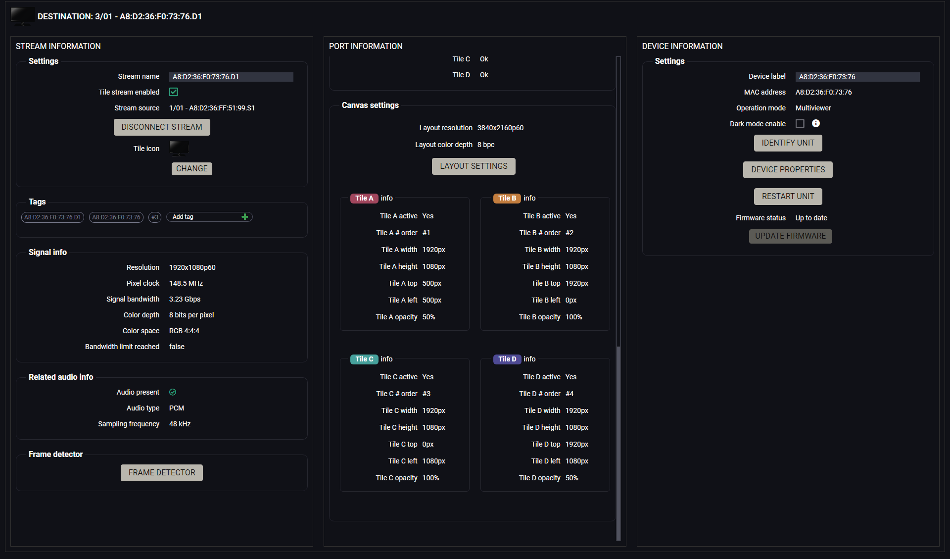
Port properties panel of the multiviewer
Stream Information
The available information and settings are the same as the Stream Information section of the Destination port panel. See the details in the Video Destination Port Properties Window section.
Port Information (Multiview Tab)
The available information and settings are the same as the Stream Information section of the Destination port panel. See the details in the Video Destination Port Properties Window section.
Multiview-specific Information Settings
▪Multiview status - the recent status of the tiles (Tile A-B-C-D).
▪Canvas settings - the resolution and color depth of the canvas. These settings can be changed in the Layout Settings window.
▪Detailed information about the tiles - activity, order, resolution, position and opacity information of each tile. The settings can be customized in the Layout Settings window.
Device Information
The available information and settings are the same as the Device Information section of the Destination port panel. See the details in the Video Destination Port Properties Window section.
Clicking on the Layout Settings button opens the layout settings window.
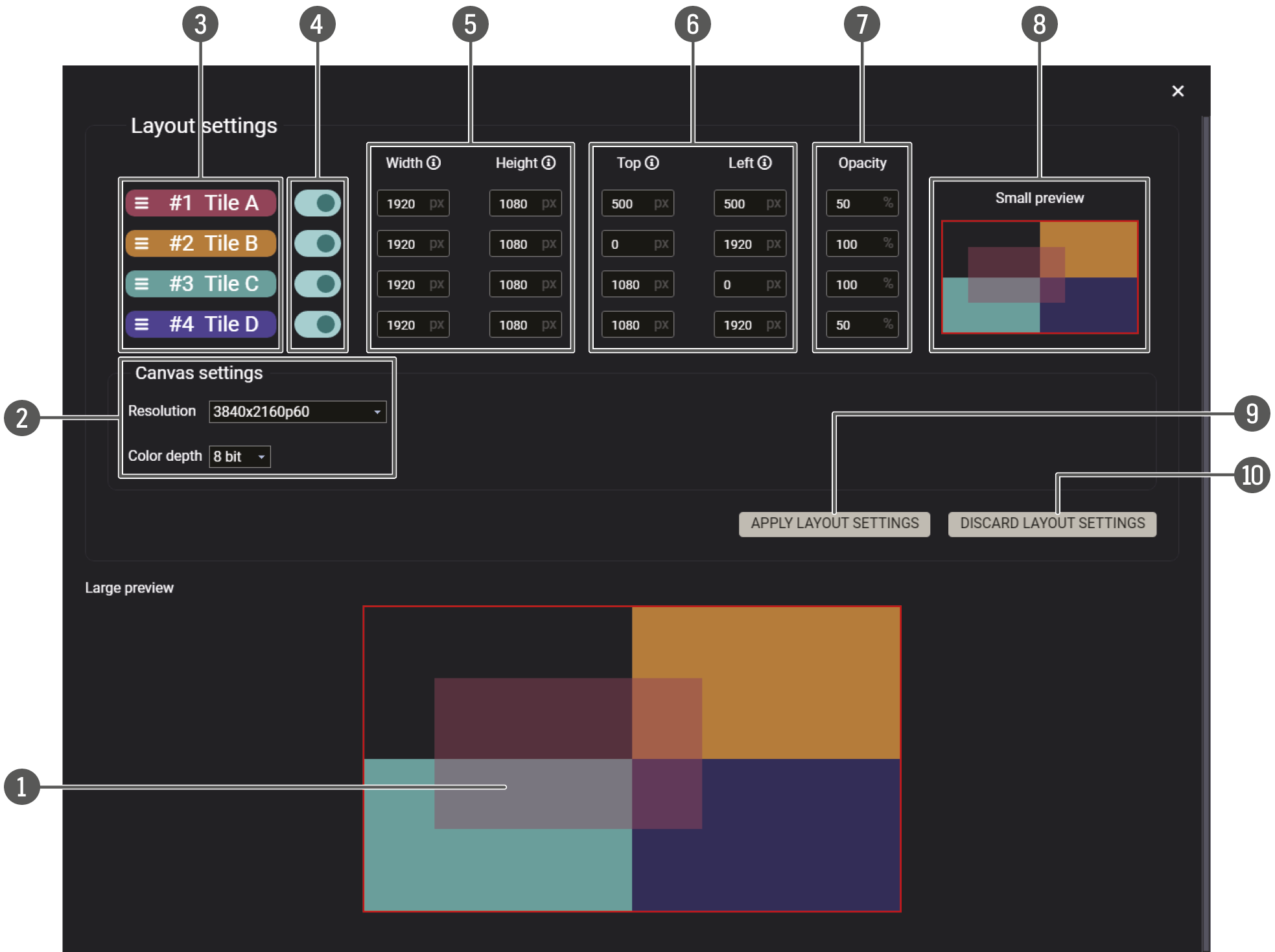
Layout settings window
Available Features and Options
|
1 |
Large preview |
After the settings are applied by clicking on the Apply Layout Settings button, the layout of the multiview tiles is displayed instantly on the large preview. |
|
2 |
Canvas settings |
The resolution and the color depth of the sink device can be set in the canvas settings. |
|
3 |
Tile order |
The order of the tiles can be changed by drag & drop using the mouse cursor. The topmost level means the tile is arranged in front of the others. |
|
4 |
Tile activation |
The tile can be enabled or disabled using the activation switcher. |
|
5 |
Tile resolution |
The resolution in width and height pixels of each tile can be set here. It must be smaller than the resolution of the canvas. |
|
6 |
Tile position |
The position of each tile on the canvas as set by adding the top and left side pixels. Tile extension over the canvas is prohibited. |
|
7 |
Opacity |
The opacity of the tile can be set in percent. 100% means fully visible, 0% is invisible. |
|
8 |
Small preview |
After the settings are applied by clicking on the Apply Layout Settings button, the layout of the multiview tiles is displayed instantly on the small preview. |
|
9 |
Apply layout settings button |
Applying and saving the modifications. |
|
q |
Discard layout settings button |
Discarding the modifications since the latest applied layout settings. |
ATTENTION!Always click on the Apply Layout Settings button to save the changes.
The device can be controlled through Lightware 3 (LW3) protocol commands to ensure the compatibility with other Lightware products. The supported LW3 commands are described in this chapter.
9.1. Overview
The Lightware Protocol #3 (LW3) is implemented in almost all new Lightware devices (matrix switchers, signal extenders and distribution amplifiers) since 2012. The protocol is ASCII-based and all commands are terminated with a carriage return (Cr, ‘\r’) and line feed (Lf, ‘\n’) pair. It is organized as a tree structure that provides outstanding flexibility and user-friendly handling with ‘nodes’, ‘properties’ and ‘methods’. The Terminal Window of the Lightware Device Controller software is the perfect tool for browsing and learning how the LW3 protocol can be used in practice.
9.2. Instructions for the Terminal Application Usage
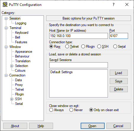
Terminal Application
The LW3 protocol commands can be applied to the UBEX matrix using a terminal application. You need to install one of them to your control device, for example Putty or CLI. #terminal
Establishing Connection
Follow the steps for establishing connection to the device:
Step 1.Connect the MMU to a LAN over Ethernet (see the details in the Matrix Management Unit (MMU) section).
Step 2.Open the terminal application (e.g. Putty).
Step 3.Add the IP address of the MMU (the default is 192.168.0.100) and the port number (6107).
Step 4.Select the Raw connection type, and open the connection.
Once the terminal window is opened, you can enter the LW3 protocol commands, which are listed in the following sections.
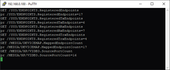
LW3 protocol command communication in a terminal window
9.3. Protocol Rules
9.3.1. LW3 Tree Structure and Command Structure (Examples)
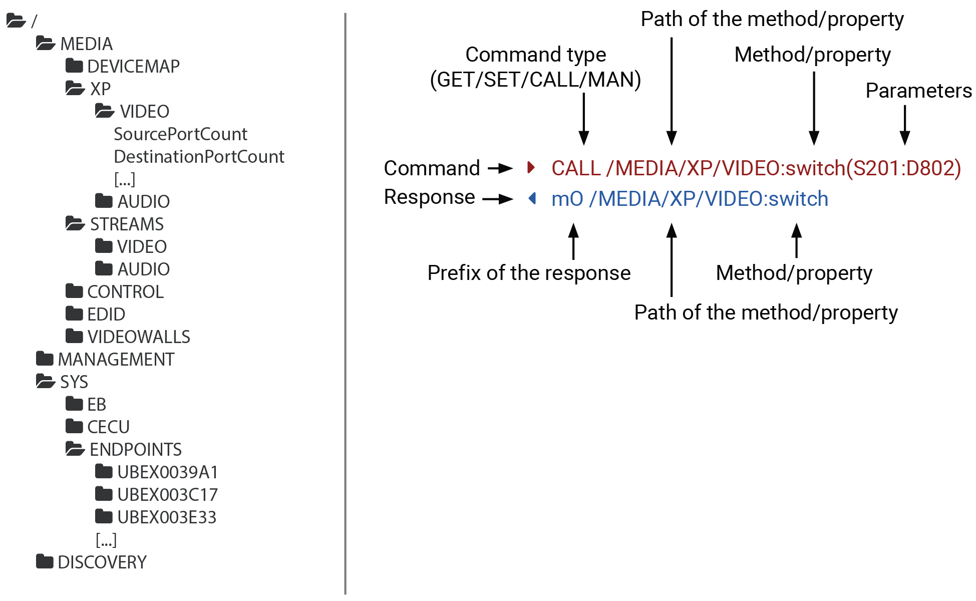
9.3.2. General Rules
▪All names and parameters are case-sensitive.
▪The nodes are separated by a slash (‘/’) character.
▪The node names are comprised of the elements of the English alphabet and numbers.
▪Use the TCP port no. 6107 when using LW3 protocol over Ethernet.
▪Node paths describe the exact location of the node, listing each parent node up to the root.
▪The length of a line (command/response, command type / prefix, path, method/property and parameters together) can be max. 800 bytes.
▪The command lines have to be closed by Carriage return and Line Feed (CrLf)
9.3.3. Command Types
GET command
The GET command can be used to get the child nodes, properties and methods of a specific node. It can also be used to get the value of a property. Use the dot character (.) when addressing a property:
»GET /.SerialNumber
«pr /.SerialNumber=87654321
GETALL command
The GETALL command can be used to get all child nodes, properties and methods of a node with one command.
»GETALL /SYS
«n- /SYS/EB
«n- /SYS/CECU
«n- /SYS/ENDPOINTS
«m- /SYS:factoryDefaults
«m- /SYS:softReset
«m- /SYS:reset
SET command
The SET command can be used to modify the value of a property. Use the dot character (.) when addressing the property:
»SET /MEDIA/STREAMS/VIDEO/S301.SourceName=My4K60Video
«pw /MEDIA/STREAMS/VIDEO/S301.SourceName=My4K60Video
CALL command
A method can be invoked by the CALL command. Use the colon character (:) when addressing the method:
»CALL /MEDIA/XP/VIDEO:switch(S101:D102)
«mO /MEDIA/XP/VIDEO:switch
MAN command
The manual is a human readable text that describes the syntax and provides a hint on how to use the primitives. For every node, property and method in the tree, there is a manual; type the MAN command to get the manual:
»MAN /MEDIA/STREAMS/VIDEO/D201/PORT.Output5vMode
«pm /MEDIA/STREAMS/VIDEO/D201/PORT.Output5vMode ["Auto" | "AlwaysOn" | "AlwaysOff"]
9.3.4. Prefix Summary
DEFINITION:The prefix is a 2-character-long code that describes the type of the response.
The following prefixes are defined in the LW3 protocol:
|
Prefix |
Description |
|
n- |
a node |
|
nE |
an error for a node |
|
nm |
a manual for a node |
|
pr |
a read-only property |
|
pw |
read-write property |
|
pE |
an error for the property |
|
pm |
a manual for the property |
|
m- |
a method |
|
mO |
a response after a successful method execution |
|
mF |
a response after a failed method execution |
|
mE |
an error for a method |
|
mm |
a manual for a method |
9.3.5. Error Messages
There are several error messages defined in the LW3 protocol, all of them have a unique error number.
»CALL /MEDIA/XP/VIDEO:switch(SA:D1)
«mE /MEDIA/XP/VIDEO:switch %E004:Invalid value
DEFINITION:An escape sequence is a sequence of characters that does not represent itself when used inside a character or string literal, but is translated into another character or a sequence of characters.
Property values and method parameters can contain characters that are used as control characters in the protocol. They must be escaped. The escape character is the backslash (‘\’), and escaping means injecting a backslash before the character that should be escaped (like in C language).
Control characters are the following: \ { } # % ( ) \r \n \t
The original message: CALL /MEDIA/CONTROL/UART/P101/PORT:sendMessage(Set(01))
The escaped message: CALL /MEDIA/CONTROL/UART/P101/PORT:sendMessage(Set\(01\))
9.3.7. Signature
DEFINITION:The signature is a four-digit-long hexadecimal value that can be optionally placed before every command to keep a command and the corresponding responses together as a group.
Each line is terminated with carriage return (Cr, ‘\r’) and line feed (Lf, ‘\n’) characters. In several cases the number of the lines in the response cannot be determined in advance, e.g. the client intends to receive the whole response and also wants to be sure that the received lines belong together and to the same command. In these cases, a special feature, the ‘signature’ can be used. The response to that particular command will also be preceded by the signature, and the corresponding lines will be between brackets:
»1700#GET /MEDIA/EDID.*
«{1700
«m- /EDID:copy
«m- /EDID:delete
«m- /EDID:reset
«m- /EDID:switch
«m- /EDID:switchAll
«}
INFO:The lines of the signature are also Cr and Lf terminated.
9.3.8. Subscription
DEFINITION:Subscription to a node means that the user will get a notification if a property of the node changes.
A user can subscribe to any node. These notifications are asynchronous messages and are useful to keep the client application up to date, without having to periodically poll the node to detect a changed property. When the user does not want to be informed about the changes anymore, he can simply unsubscribe from the node.
ATTENTION!The subscriptions are handled separately for connections. Hence, if the connection is terminated, all registered subscriptions are deleted. After reopening a connection all subscribe commands have to be sent in order to get the notifications of the changes on that connection.
Subscribe to a Node
»OPEN /MEDIA/VIDEO
«o- /MEDIA/VIDEO
Subscribe to Multiple Nodes
»OPEN /MEDIA/VIDEO/*
«o- /MEDIA/VIDEO/*
Unsubscribe from a Node
»CLOSE /MEDIA/VIDEO
«c- /MEDIA/VIDEO
Get the Active Subscriptions
»OPEN
«o- /MEDIA/VIDEO
«o- /EDID
«o- /DISCOVERY
Unsubscribe from Multiple Nodes
»CLOSE /MEDIA/VIDEO/*
«c- /MEDIA/VIDEO/*
9.3.9. Notifications about the Changes of the Properties
When the value of a property is changed and the user is subscribed to the node that the property belongs to, an asynchronous notification is generated. This notification is called the ‘change message’. The format of such a message is very similar to the response for the GET command:
«CHG /MEDIA/XP/VIDEO.SourcePortCount=10
A Short Example of How to Use the Subscription
There are two independent users controlling the device through two independent connections (Connection #1 and Connection #2). The events in the rows occur after each other.
|
»OPEN /MANAGEMENT/LABEL «o- /MANAGEMENT/LABEL »GET /MANAGEMENT/LABEL.DeviceLabel «pm /MANAGEMENT/LABEL.DeviceLabel=UBEX-MMU-X200 |
connection #1 |
|
»GET /MANAGEMENT/LABEL.DeviceLabel «pm /MANAGEMENT/LABEL.DeviceLabel=UBEX-MMU-X200 »SET /MANAGEMENT/LABEL.DeviceLabel=MMU_ServerRoom «pw /MANAGEMENT/LABEL.DeviceLabel=MMU_ServerRoom |
connection #2 |
|
«CHG /MANAGEMENT/LABEL.DeviceLabel=MMU_ServerRoom |
connection #1 |
Explanation: The first user (Connection #1) set a subscription to a node. Later the other user (Connection #2) made a change, and thanks to the subscription, the first user got a notification about the change.
9.3.10. Legend for the Control Commands
|
Format |
Description |
|
<in> |
Stream source ID |
|
<out> |
Output port ID |
|
<port> |
Interface port ID |
|
<parameter> |
Specific property defined and described in the command |
|
<expression> |
Batched argument: the underline means that more expressions or parameters can be placed using a semicolon, e.g. S101;S102;S401 or S101:D301;S302:D201 |
|
<UBEX_EP> |
UBEX endpoint ID, e.g. UBEXF254D9 |
|
<dev_ID> |
Logical device ID of the UBEX endpoint |
|
<link> |
SFP+ link number |
|
|
Sent command |
|
|
Received response |
|
• |
Space character |
|
| |
Separator line ("or" character) |
9.4. The Tree Structure of the UBEX Matrix
When the UBEX matrix builds up and starts to operate, the individual endpoints and the MMU cease to be individual devices, but the whole system becomes one big tree structure including all UBEX devices which are the part of the matrix.
When you connect one of endpoints you always will reach the LW3 tree of the MMU. The endpoints can be controlled over the MMU only.
9.4.1. The Tree Structure of the MMU
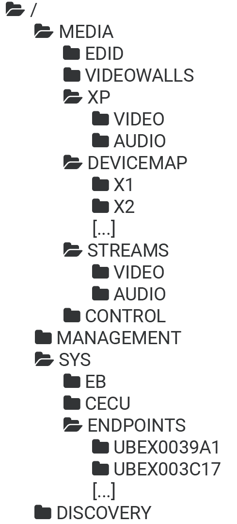
9.4.2. Endpoint ID Calculation
The endpoint devices of the matrix are listed under the /SYS/ENDPOINTS node by the MAC address. The formula is the following:
|
MAC address of the endpoint |
The last 6 characters of the MAC address |
Endpoint node under /SYS |
|
A8:D2:36:00:39:A1 |
0039A1 |
UBEX0039A1 |
Where the path of a LW3 command/method/etc contains a UBEX endpoint, the following parameter refers to it: <UBEX_EP>
All endpoint devices which are connected to the UBEX matrix got a logical device ID generated by the MMU.
DEFINITION:Logical device ID means the MMU assigns a number to the endpoints ordered by the discovery. For example the first endpoint gets the 1 (appears as X1 under the DEVICEMAP), the second one the 2 (appears as X2).
The stream ID is based on the logical device ID. The registered endpoint can be transmitter, receiver, or transceiver. All transmitters have two inputs, all receivers have two outputs, and all transceivers have one input and one output. The first discovered endpoint gets the X1 logical device ID, the HDMI port 1 of the endpoint is always the 01 number, the HDMI port 2 is always the 02 number. If the endpoint has input port (TX / TRX), it is signed with S as Source, if it has output port (RX / TRX), it is signed with D as Destination. The formula is the following:
<Port_type><Logical_device_ID><Port_number>
Two endpoint devices cannot be assigned to the same logical device ID. The number is always calculated for the endpoints independently from the operation mode.
INFO:The logical device ID (and the order of the endpoints) can be changed by the LDC software (see the details in the Device Map section) or by LW3 protocol command (see the details in the Assigning an Endpoint to a Logical Device ID section).
INFO:The operation mode (TX, RX, or TRX) can be changed for any endpoint. See the related LW3 protocol command in the Set the Operation Mode section.
Example
The following table helps to clear up the calculation of the stream ID:
|
Operation mode |
Port number |
Stream ID |
Description |
Discovery order |
|
|
TX (Transmitter) |
HDMI in 1 |
S101 |
Processed stream |
1. |
|
|
S103 |
Native stream |
||||
|
HDMI in 2 |
S102 |
Processed stream |
|||
|
S104 |
Native stream |
||||
|
RX (Receiver) |
HDMI out 1 |
D201 |
Processed stream |
2. |
|
|
HDMI out 2 |
D202 |
Processed stream |
|||
|
TRX (Transceiver) |
HDMI in 2 |
S302 |
Processed stream |
3. |
|
|
HDMI out 1 |
D301 |
Processed stream |
|||
|
RXMV (Multiviewer) |
HDMI out 1 |
D401 |
Multiview streams |
Tile 1 |
4. |
|
D402 |
Tile 2 |
||||
|
D403 |
Tile 3 |
||||
|
D404 |
Tile 4 |
||||
|
HDMI out 2 |
D405 |
Processed stream |
|||
9.5. System Commands - MMU
INFO:The device label can be changed to a custom text in the Status Tab of the LDC software.
This property can be changed to a custom text. The default format of the device label is the following: LW_<product_name>_<serial_no>
The Device Label can be 39 characters long and ASCII characters are allowed. Longer names will be truncated.
Command and Response #label #devicelabel
»SET•/MANAGEMENT/LABEL.DeviceLabel=<custom_name>
«pw•/MANAGEMENT/LABEL.DeviceLabel=<custom_name>
Example
»SET /MANAGEMENT/LABEL.DeviceLabel=MMU_ServerRoom
«pw /MANAGEMENT/LABEL.DeviceLabel=MMU_ServerRoom
ATTENTION!The name of the product is a read-only parameter and cannot be modified.
Command and Response
»GET•/.ProductName
«pr•/.ProductName=<Product_name>
Example
»GET /.ProductName
«pr /.ProductName=UBEX-MMU-X200
9.5.3. Query the Firmware Package Version
Command and Response #firmwareversion
»GET•/MANAGEMENT/UID/PACKAGE.Version
«pr•/MANAGEMENT/UID/PACKAGE.Version=<firmware_version>
Example
»GET /MANAGEMENT/UID/PACKAGE.Version
«pr /MANAGEMENT/UID/PACKAGE.Version=v2.3.0b12
9.5.4. Query the Date and Time of the System
The query returns with the current date and time which is set in the MMU. The format is based on the ISO 8601 standard.
Command and Response #time #date
»GET•/MANAGEMENT/DATETIME.CurrentTime
«pr•/MANAGEMENT/DATETIME.CurrentTime=<date_time>
Parameters
|
Parameter |
Description |
Formula |
|
<date_time> |
Current date and time |
YYYY-MM-DDTHH:MM:SS |
Example
»GET /MANAGEMENT/DATETIME.CurrentTime
«pr /MANAGEMENT/DATETIME.CurrentTime=2024-09-30T06:23:37
9.5.5. Setting of the Date and Time Manually
The date and time format is based on the ISO 8601 standard.
Command and Response
»CALL•/MANAGEMENT/DATETIME:setTime=<date_time>
«mO•/MANAGEMENT/DATETIME:setTime
Parameters
See at the previous section.
Example
»CALL /MANAGEMENT/DATETIME:setTime=2025-12-24T20:00:15
«mO /MANAGEMENT/DATETIME.setTime
DEFINITION:The Network Time Protocol (NTP) is a networking protocol for clock synchronization between computer systems over packet-switched, variable-latency data networks.
Command and Response #ntp
»SET•/MANAGEMENT/DATETIME.NtpServerAddress=<server_address>
«pw•/MANAGEMENT/DATETIME.NtpServerAddress=<server_address>
Example
»SET /MANAGEMENT/DATETIME.NtpServerAddress=pool.ntp.org
«pw /MANAGEMENT/DATETIME.NtpServerAddress=pool.ntp.org
DEFINITION:The Network Time Protocol (NTP) is a networking protocol for clock synchronization between computer systems over packet-switched, variable-latency data networks.
Command and Response
»SET•/MANAGEMENT/DATETIME.EnableNtp=<logical_value>
«pw•/MANAGEMENT/DATETIME.EnableNtp=<logical_value>
Parameters
|
Parameter |
Parameter description |
Value |
Value description |
|
<logical_value> |
NTP service is enabled or disabled. |
true |
NTP is enabled. |
|
false |
NTP is disabled. |
Example
»SET /MANAGEMENT/DATETIME.EnableNtp=true
«pw /MANAGEMENT/DATETIME.EnableNtp=true
9.5.8. Setting the Brightness of the LCD Screen
Command and Response
»SET•/SYS/CECU/LCD.Brightness=<parameter>
«pw•/SYS/CECU/LCD.Brightness=<parameter>
Parameters
The <parameter> of display brightness can be set between 0 and 10 values.
Example
»SET /SYS/CECU/LCD.Brightness=5
«pw /SYS/CECU/LCD.Brightness=5
9.5.9. Software Resetting the Device
The core application of the Matrix Management Unit can be restarted.
INFO:The video signal transmission is not affected by the software resetting of the MMU.
Command and Response #softreset
»CALL•/SYS:softReset()
«mO•/SYS:softReset
Example
»CALL /SYS:softReset()
«mO /SYS:softReset
The Matrix Management Unit can be restarted – the current connections will be terminated.
INFO:The video signal transmission is not affected by the rebooting of the MMU.
Command and Response #restart #reboot #reset
»CALL•/SYS:reset()
«mO•/SYS:reset
Example
»CALL /SYS:reset()
«mO /SYS:reset
9.5.11. Restore the Factory Default Settings
Command and Response #factory
»CALL•/SYS:factoryDefaults()
«mO•/SYS:factoryDefaults
Example
»CALL /SYS:factoryDefaults()
«mO /SYS:factoryDefaults
The device is restarted, current connections are terminated, and the default settings are restored. See the complete list in the UBEX-MMU-X200 section.
9.6. System Commands - Endpoints
Parameters
|
Parameter |
Description |
Formula |
|
<UBEX_EP> |
UBEX endpoint ID |
UBEX<last_6_characters_of_the_MAC_address> |
INFO:The device label can be changed to a custom text in the LDC software. See the details about the device renaming in the Device Information section for the source side and the Device Information section for the Destination side.
This property can be changed to a custom text. The default format of the device label is the following: LW_<product_name>_<serial_no>
The Device Label can be 64 characters long and ASCII characters are allowed. Longer names will be truncated.
Command and Response #label #devicelabel
»SET•/SYS/ENDPOINTS/<UBEX_EP>.DeviceLabel=<custom_name>
«pw•/SYS/ENDPOINTS/<UBEX_EP>.DeviceLabel=<custom_name>
Example
»SET /SYS/ENDPOINTS/UBEX0039A1.DeviceLabel=UBEX_RX_Theater
«pw /SYS/ENDPOINTS/UBEX0039A1.DeviceLabel=UBEX_RX_Theater
ATTENTION!The name of the product is a read-only parameter and cannot be modified.
Command and Response
»GET•/SYS/ENDPOINTS/<UBEX_EP>.ProductName
«pr•/SYS/ENDPOINTS/<UBEX_EP>.ProductName=<Product_name>
Example
»GET /SYS/ENDPOINTS/UBEX0039A1.ProductName
«pr /SYS/ENDPOINTS/UBEX0039A1.ProductName=UBEX-PRO20-HDMI-F130
9.6.3. Query the Operation Mode
Command and Response #operationmode #transmitter #receiver #transceiver #tx #rx #trx
»GET•/SYS/ENDPOINTS/<UBEX_EP>.OperationMode
«pw•/SYS/ENDPOINTS/<UBEX_EP>.OperationMode=<operation_mode>
Parameters
|
Parameter |
Parameter description |
Value |
Value description |
|
<operation_mode> |
The operation mode of the endpoint device |
Transmitter |
The endpoint device operates as a Transmitter. See the details in the Transmitter Mode section. |
|
Receiver |
The endpoint device operates as a Receiver. See the details in the Receiver Mode section. |
||
|
Transceiver |
The endpoint device operates as a Transceiver. See the details in the Transceiver Mode section. |
||
|
Multiviewer |
The endpoint device is set to Multiviewer. See the details in the Multiviewer Mode section. |
Example
»GET /SYS/ENDPOINTS/UBEX0039A1.OperationMode
«pw /SYS/ENDPOINTS/UBEX0039A1.OperationMode=Transceiver
ATTENTION!This operation always requires rebooting the endpoint device.
INFO:The setting is stored in the MMU.
The operation mode (transmitter, receiver, transceiver or multiviewer) of the device can be changed based on the required application. #operationmode #transmitter #receiver #transceiver #multiviewer #tx #rx #trx #rxmv
Command and Response
»SET•/SYS/ENDPOINTS/<UBEX_EP>.OperationMode=<operation_mode>
«pw•/SYS/ENDPOINTS/<UBEX_EP>.OperationMode=<operation_mode>
Parameters
|
Parameter |
Parameter description |
Value |
Value description |
|
<operation_mode> |
The operation mode of the endpoint device |
Transmitter |
The endpoint device is set to Transmitter. See the details in the Transmitter Mode section. |
|
Receiver |
The endpoint device is set to Receiver. See the details in the Receiver Mode section. |
||
|
Transceiver |
The endpoint device is set to Transceiver. See the details in the Transceiver Mode section. |
||
|
Multiviewer |
The endpoint device is set to Multiviewer. See the details in the Multiviewer Mode section. |
Example
»SET /SYS/ENDPOINTS/UBEX0039A1.OperationMode=Receiver
«pw /SYS/ENDPOINTS/UBEX0039A1.OperationMode=Receiver
9.6.5. Query the MAC Address of the Device
Command and Response #mac
»GET•/SYS/ENDPOINTS/<UBEX_EP>.MacAddress
«pr•/SYS/ENDPOINTS/<UBEX_EP>.MacAddress=<MAC_address>
Example
»GET /SYS/ENDPOINTS/UBEX0039A1.MacAddress
«pr /SYS/ENDPOINTS/UBEX0039A1.MacAddress=A8:D2:36:00:39:DA
9.6.6. Query the Firmware Package Version
Command and Response #firmwareversion
»GET•/SYS/ENDPOINTS/<UBEX_EP>.PackageVersion
«pr•/SYS/ENDPOINTS/<UBEX_EP>.PackageVersion=<version>
Example
»GET /SYS/ENDPOINTS/UBEX0039A1.PackageVersion
«pr /SYS/ENDPOINTS/UBEX0039A1.PackageVersion=v3.4.0b7

Calling the method results in the blinking of the front panel status LEDs for 10 seconds. This feature can be used to help to identify the device itself in the rack shelf.
Command and Response #identifyme
»CALL•/SYS/ENDPOINTS/<UBEX_EP>:identifyMe()
«mO•/SYS/ENDPOINTS/<UBEX_EP>:identifyMe
Example
»CALL /SYS/ENDPOINTS/UBEX0039A1:identifyMe()
«mO /SYS/ENDPOINTS/UBEX0039A1:identifyMe
Enable/disable the operation of the jog dial control knob.
Command and Response #controllock
»SET•/SYS/ENDPOINTS/<UBEX_EP>/SETTINGS/UI.ControlLock=<parameter>
«pw•/SYS/ENDPOINTS/<UBEX_EP>/SETTINGS/UI.ControlLock=<parameter>
Parameters
|
Parameter |
Parameter description |
Value |
Value description |
|
<parameter> |
Lock/unlock of the jog dial control knob |
0 |
The jog dial control knob is unlocked. |
|
1 |
The jog dial control knob is locked. |
||
|
2 |
The jog dial control knob is ForceLocked. |
INFO:There is no difference between the 1 and 2 mode from the operation's point of view.
Example
»SET /SYS/ENDPOINTS/UBEX0039A1/SETTINGS/UI.ControlLock=1
«pw /SYS/ENDPOINTS/UBEX0039A1/SETTINGS/UI.ControlLock=1

Rental application requires this function, which keeps the LCD screen and the LEDs unlit to hide the device during an event.
Command and Response #darkmode
»SET•/SYS/ENDPOINTS/<UBEX_EP>/SETTINGS/UI/DARKMODE.DarkModeEnable=<logical_value>
«pw•/SYS/ENDPOINTS/<UBEX_EP>/SETTINGS/UI/DARKMODE.DarkModeEnable=<logical_value>
Parameters
|
Parameter |
Parameter description |
Value |
Value description |
|
<logical_value> |
Enable or disable the dark mode feature |
true |
Dark mode will be enabled after the delay time expired (see next section). |
|
false |
Dark mode is disabled. |
Example
»SET /SYS/ENDPOINTS/UBEX0039A1/SETTINGS/UI/DARKMODE.DarkModeEnable=true
«pw /SYS/ENDPOINTS/UBEX0039A1/SETTINGS/UI/DARKMODE.DarkModeEnable=true
9.6.10. Dark Mode Delay Setting
When the dark mode feature is enabled (see the previous section), it will be launched after the delay time expired.
Command and Response
»SET•/SYS/ENDPOINTS/<UBEX_EP>/SETTINGS/UI/DARKMODE.DarkModeDelay=<second>
«pw•/SYS/ENDPOINTS/<UBEX_EP>/SETTINGS/UI/DARKMODE.DarkModeDelay=<second>
Example
»SET /SYS/ENDPOINTS/UBEX0039A1/SETTINGS/UI/DARKMODE.DarkModeDelay=10
«pw /SYS/ENDPOINTS/UBEX0039A1/SETTINGS/UI/DARKMODE.DarkModeDelay=10
9.6.11. Setting the Rotary Direction of the Jog Dial Knob
Command and Response #rotary #jogdial
»SET•/SYS/ENDPOINTS/<UBEX_EP>/SETTINGS/UI.RotaryDirection=<parameter>
«pw•/SYS/ENDPOINTS/<UBEX_EP>/SETTINGS/UI.RotaryDirection=<parameter>
Parameters
|
Parameter |
Parameter description |
Value |
Value description |
|
<parameter> |
Rotary direction of the jog dial control knob |
0 |
The rotary direction of down is clockwise (CW). |
|
1 |
The rotary direction of down is counter clockwise (CCW). |
Example
»SET /SYS/ENDPOINTS/UBEX0039A1/SETTINGS/UI.RotaryDirection=1
«pw /SYS/ENDPOINTS/UBEX0039A1/SETTINGS/UI.RotaryDirection=1
9.6.12. Setting the Brightness of the LCD Screen
Command and Response
»SET•/SYS/ENDPOINTS/<UBEX_EP>/SETTINGS/UI.DisplayBrightness=<parameter>
«pw•/SYS/ENDPOINTS/<UBEX_EP>/SETTINGS/UI.DisplayBrightness=<parameter>
Parameters
The <parameter> of display brightness can be set between 0 and 10 values.
Example
»SET /SYS/ENDPOINTS/UBEX0039A1/SETTINGS/UI.DisplayBrightness=5
«pw /SYS/ENDPOINTS/UBEX0039A1/SETTINGS/UI.DisplayBrightness=5
The device can be set to bootload (service / firmware update) mode. The AV signal transmission is terminated in this mode.
Command and Response #bootload
»CALL•/SYS/ENDPOINTS/<UBEX_EP>:bootload()
«mO•/SYS/ENDPOINTS/<UBEX_EP>:bootload
Example
»CALL /SYS/ENDPOINTS/UBEX0039A1:bootload()
«mO /SYS/ENDPOINTS/UBEX0039A1:bootload
Calling the method results in the endpoints restarting – the connection with the remote device and the signal transmission will be terminated. After rebooting, the configuration settings are reloaded and the connection with the remote device is established again.
Command and Response #restart #reboot #reset
»CALL•/SYS/ENDPOINTS/<UBEX_EP>:reset()
«mO•/SYS/ENDPOINTS/<UBEX_EP>:reset
Example
»CALL /SYS/ENDPOINTS/UBEX0039A1:reset()
«mO /SYS/ENDPOINTS/UBEX0039A1:reset
9.6.15. Restore the Factory Default Settings
Command and Response #factory
»CALL•/SYS/ENDPOINTS/<UBEX_EP>:factoryDefaults()
«mO•/SYS/ENDPOINTS/<UBEX_EP>:factoryDefaults
Example
»CALL /SYS/ENDPOINTS/UBEX0039A1:factoryDefaults()
«mO /SYS/ENDPOINTS/UBEX0039A1:factoryDefaults
The device is restarted, current connections are terminated, and the default settings are restored. See the complete list in the Factory Default Settings section.
9.7. Endpoint Management Commands
Parameters #endpointmanagement
|
Parameter |
Description |
Formula |
|
<UBEX_EP> |
UBEX endpoint ID |
UBEX<last_6_characters_of_the_MAC_address> |
9.7.1. Query the Number of Registered Endpoints
The query returns with the number of registered endpoints (transmitters, receivers, and transceivers together) in the UBEX matrix. This number contains all endpoints which had been registered once by the MMU.
Command and Response
»GET•/SYS/ENDPOINTS.RegisteredEndpoints
«pr•/SYS/ENDPOINTS.RegisteredEndpoints=<number>
Example
»GET /SYS/ENDPOINTS.RegisteredEndpoints
«pr /SYS/ENDPOINTS.RegisteredEndpoints=45
9.7.2. Query the Number of Connected Endpoints
The query returns with the number of the currently connected endpoints (transmitters, receivers, and transceivers together) in the UBEX matrix.
Command and Response
»GET•/SYS/ENDPOINTS.ConnectedEndpoints
«pr•/SYS/ENDPOINTS.ConnectedEndpoints=<number>
Example
»GET /SYS/ENDPOINTS.ConnectedEndpoints
«pr /SYS/ENDPOINTS.ConnectedEndpoints=44
9.7.3. Query the Number of Registered Transmitters
The query returns with the number of registered transmitters in the UBEX matrix. This number contains all transmitters which had been registered once by the MMU.
Command and Response
»GET•/SYS/ENDPOINTS.RegisteredTxEndpoints
«pr•/SYS/ENDPOINTS.RegisteredTxEndpoints=<number>
Example
»GET /SYS/ENDPOINTS.RegisteredTxEndpoints
«pr /SYS/ENDPOINTS.RegisteredTxEndpoints=16
9.7.4. Query the Number of Connected Transmitters
The query returns with the number of the currently connected transmitters in the UBEX matrix.
Command and Response
»GET•/SYS/ENDPOINTS.ConnectedTxEndpoints
«pr•/SYS/ENDPOINTS.ConnectedTxEndpoints=<number>
Example
»GET /SYS/ENDPOINTS.ConnectedTxEndpoints
«pr /SYS/ENDPOINTS.ConnectedTxEndpoints=13
9.7.5. Query the Number of Registered Receivers
The query returns with the number of registered receivers in the UBEX matrix. This number contains all receivers which had been registered once by the MMU.
Command and Response
»GET•/SYS/ENDPOINTS.RegisteredRxEndpoints
«pr•/SYS/ENDPOINTS.RegisteredRxEndpoints=<number>
Example
»GET /SYS/ENDPOINTS.RegisteredRxEndpoints
«pr /SYS/ENDPOINTS.RegisteredRxEndpoints=28
9.7.6. Query the Number of Connected Receivers
The query returns with the number of the currently connected receivers in the UBEX matrix.
Command and Response
»GET•/SYS/ENDPOINTS.ConnectedRxEndpoints
«pr•/SYS/ENDPOINTS.ConnectedRxEndpoints=<number>
Example
»GET /SYS/ENDPOINTS.ConnectedRxEndpoints
«pr /SYS/ENDPOINTS.ConnectedRxEndpoints=25
9.7.7. Query the Number of Registered Transceivers
The query returns with the number of registered transceivers in the UBEX matrix. This number contains all receivers which had been registered once by the MMU.
Command and Response
»GET•/SYS/ENDPOINTS.RegisteredTrxEndpoints
«pr•/SYS/ENDPOINTS.RegisteredTrxEndpoints=<number>
Example
»GET /SYS/ENDPOINTS.RegisteredTrxEndpoints
«pr /SYS/ENDPOINTS.RegisteredTrxEndpoints=28
9.7.8. Query the Number of Connected Transceivers
The query returns with the number of the currently connected transceivers in the UBEX matrix.
Command and Response
»GET•/SYS/ENDPOINTS.ConnectedTrxEndpoints
«pr•/SYS/ENDPOINTS.ConnectedTrxEndpoints=<number>
Example
»GET /SYS/ENDPOINTS.ConnectedTrxEndpoints
«pr /SYS/ENDPOINTS.ConnectedTrxEndpoints=25
9.7.9. Query the Connection Status of an Endpoint
Command and Response
»GET•/SYS/ENDPOINTS/<UBEX_EP>.ConnectionStatus
«pr•/SYS/ENDPOINTS/<UBEX_EP>.ConnectionStatus=<status>
Parameters
|
Parameter |
Parameter description |
Value |
Value description |
|
<status> |
Connection status of the selected endpoint |
Offline |
The device powered off or not connected to the UBEX matrix. |
|
Connecting |
The device is establishing connection to the UBEX matrix. |
||
|
Online |
The device is powered on and ready to use in the UBEX matrix. |
Example
»GET /SYS/ENDPOINTS/UBEX0039A1.ConnectionStatus
«pr /SYS/ENDPOINTS/UBEX0039A1.ConnectionStatus=Online
9.7.10. Query the Claiming Status of an Endpoint
Command and Response
»GET•/SYS/ENDPOINTS/<UBEX_EP>.ClaimingStatus
«pr•/SYS/ENDPOINTS/<UBEX_EP>.ClaimingStatus=<status>
Parameters
|
Parameter |
Parameter description |
Value |
Value description |
|
<status> |
Claiming status of the selected endpoint |
Unclaiming |
The device is under the unclaiming procedure, it can be after the running of the unclaimEndpoint() or unclaimAllEndpoint() commands typically. |
|
Initializing |
The device is under initialization, it can be during the first connecting to the MMU typically. |
||
|
Claiming |
The device is under the claiming procedure. |
||
|
Reclaiming |
The device is under the reclaiming procedure, it can be after operation mode changing typically. |
||
|
Restoring |
The device is under the restoring procedure, it can be during rebooting of a claimed endpoint device. |
||
|
Claimed |
The device is claimed by the MMU and ready to use in the UBEX matrix. |
Example
»GET /SYS/ENDPOINTS/UBEX0039A1.ClaimingStatus
«pr /SYS/ENDPOINTS/UBEX0039A1.ClaimingStatus=Claimed
9.7.11. Unclaiming an Endpoint
The command makes the selected endpoint to be unclaimed from the UBEX matrix.
Command and Response
»CALL•/SYS/ENDPOINTS:unclaimEndpoint(<UBEX_EP>)
«mO•/SYS/ENDPOINTS:unclaimEndpoint
Example
»CALL /SYS/ENDPOINTS:unclaimEndpoint(UBEX0039A1)
«mO /SYS/ENDPOINTS:unclaimEndpoint
9.7.12. Unclaiming All Endpoints
The command makes all endpoints to be unclaimed from the UBEX matrix.
Command and Response
»CALL•/SYS/ENDPOINTS:unclaimAllEndpoint()
«mO•/SYS/ENDPOINTS:unclaimAllEndpoint
Example
»CALL /SYS/ENDPOINTS:unclaimAllEndpoint()
«mO /SYS/ENDPOINTS:unclaimAllEndpoint
9.7.13. Query the Number of the Mapped Endpoints
The query returns the number of mapped endpoint which got a logical device ID. This number is equal with the result of the Query the Number of Registered Endpoints.
Command and Response
»GET•/MEDIA/DEVICEMAP.MappedEndpointCount
«pr•/MEDIA/DEVICEMAP.MappedEndpointCount=<number>
Example
»GET /MEDIA/DEVICEMAP.MappedEndpointCount
«pr /MEDIA/DEVICEMAP.MappedEndpointCount=45
9.7.14. Query the Endpoint ID of a Logical Device ID
The query returns with the UBEX endpoint ID assigned to the selected logical device ID.
Command and Response
»GET•/MEDIA/DEVICEMAP.<logical_device_ID>
«pr•/MEDIA/DEVICEMAP.<logical_device_ID>=<UBEX_EP>
Example
»GET /MEDIA/DEVICEMAP.X1
«pr /MEDIA/DEVICEMAP.X1=UBEX0039A1
9.7.15. Assigning an Endpoint to a Logical Device ID
Calling the method results the selected endpoint can be assigned to the desired logical device ID. This method is equal to the endpoint re-ordering in the Device Map of the Lightware Device Controller (LDC)software.
Command and Response #devicemap
»CALL•/MEDIA/DEVICEMAP:assign(logical_device_ID:<UBEX_EP>)
«mO•/MEDIA/DEVICEMAP:assign
Example
»CALL /MEDIA/DEVICEMAP:assign(X3:UBEX0039A1;X1:UBEX003958)
«mO /MEDIA/DEVICEMAP:assign
9.8. Video Crosspoint Settings
Parameters #switch #crosspoint
|
Parameter |
Description |
Formula |
|
<in> |
Input stream coming from the TX / TRX |
S<logical_devive_ID><stream_nr> |
|
<out> |
Output port of the RX / TRX |
D<logical_device_ID><out_port_nr> |
9.8.1. Switching the Video Stream to One Destination
Command and Response
»CALL•/MEDIA/XP/VIDEO:switch(<in>:<out>)
«mO•/MEDIA/XP/VIDEO:switch
Example
»CALL /MEDIA/XP/VIDEO:switch(S501:D302;S102:D102)
«mO /MEDIA/XP/VIDEO:switch
9.8.2. Switching a Video Stream to All Destinations
The selected video stream is switched to all outputs.
Command and Response
»CALL•/MEDIA/XP/VIDEO:switchAll(<in>)
«mO•/MEDIA/XP/VIDEO:switchAll
Example
»CALL /MEDIA/XP/VIDEO:switchAll(S101)
«mO /MEDIA/XP/VIDEO:switchAll
9.8.3. Disconnecting the Stream
Command and Response #disconnect #crosspoint
»CALL•/MEDIA/XP/VIDEO:switch(0:<destination>)
«mO•/MEDIA/XP/VIDEO:switch
Example
»CALL /MEDIA/XP/VIDEO:switch(0:D101;0:D202)
«mO /MEDIA/XP/VIDEO:switch
D101 and D202 sinks disconnected from the actual stream.
9.8.4. Query the Status of All Video Ports
The query returns with all information about the source streams and the destinations. The respond contains the following information: #status
▪Enable/disable status
▪Signal presence
▪Crosspoint status (which stream is connected to the destination port)
▪Bandwidth information
▪Source/destination names, tags
▪Device tags
▪Resolution, refresh rate
▪HDCP information
▪Locking status
Command and Response
»GET•/MEDIA/XP/VIDEO/*.*
«pr•/MEDIA/XP/VIDEO/*.*
9.8.5. Query the Number of the Source Ports
The query returns with the number of all source (input) ports including the disabled ones.
Command and Response
»GET•/MEDIA/XP/VIDEO.SourcePortCount
«pr•/MEDIA/XP/VIDEO.SourcePortCount=<number>
Example
»GET /MEDIA/XP/VIDEO.SourcePortCount
«pr /MEDIA/XP/VIDEO.SourcePortCount=21
9.8.6. Query the Number of the Destination Ports
The query returns with the number of all destination (output) ports including the disabled ones.
Command and Response
»GET•/MEDIA/XP/VIDEO.DestinationPortCount
«pr•/MEDIA/XP/VIDEO.DestinationPortCount=<number>
Example
»GET /MEDIA/XP/VIDEO.DestinationPortCount
«pr /MEDIA/XP/VIDEO.DestinationPortCount=23
9.9. Video Stream Settings - Source (Input) Side
Parameters
|
Parameter |
Description |
Formula |
|
<in> |
Input stream coming from the TX / TRX |
S<logical_devive_ID><stream_nr> |
9.9.1. Query the Name of the Stream
INFO:The default name of the stream is the MAC address of the endpoint device and the stream number separated by a dot. Example: A8:D2:36:F0:00:03.S1
Command and Response
»GET•/MEDIA/STREAMS/VIDEO/<in>.SourceName
«pw•/MEDIA/STREAMS/VIDEO/<in>.SourceName=<name>
Example
»GET /MEDIA/STREAMS/VIDEO/S2301.SourceName
«pw /MEDIA/STREAMS/VIDEO/S2301.SourceName=Casablanca
9.9.2. Setting the Name of the Stream
Command and Response
»SET•/MEDIA/STREAMS/VIDEO/<in>.SourceName=<name>
«pw•/MEDIA/STREAMS/VIDEO/<in>.SourceName=<name>
Example
»SET /MEDIA/STREAMS/VIDEO/S102.SourceName=MyLittlePony_S01E01
«pw /MEDIA/STREAMS/VIDEO/S102.SourceName=MyLittlePony_S01E01
9.9.3. Query the Tags of the Stream
The query returns with the tags which are added by the user.
Command and Response #tag
»GET•/MEDIA/STREAMS/VIDEO/<in>.Tags
«pr•/MEDIA/STREAMS/VIDEO/<in>.Tags=<tag>
Example
»GET /MEDIA/STREAMS/VIDEO/S102.Tags
«pr /MEDIA/STREAMS/VIDEO/S102.Tags=4K60;movie;Die_Hard_2
9.9.4. Adding Tags to the Stream
The following characters are allowed in the <tag> parameter: non-capital letters (a-z), capital letters (A-Z), numbers (0-9), and special characters ( - . _ ~ : / ? # [ ] @ ! $ & ( ) + = * ).
Command and Response
»CALL•/MEDIA/STREAMS/VIDEO/<in>:addTags(<tag>)
«mO•/MEDIA/STREAMS/VIDEO/<in>:addTags=
Example
»CALL /MEDIA/STREAMS/VIDEO/S401:addTags(4K30;intro)
«mO /MEDIA/STREAMS/VIDEO/S401:addTags=
9.9.5. Deleting Tags of the Stream
Command and Response
»CALL•/MEDIA/STREAMS/VIDEO/<in>:removeTags(<tag>)
«mO•/MEDIA/STREAMS/VIDEO/<in>:removeTags=
Example
»CALL /MEDIA/STREAMS/VIDEO/S101:removeTags(cartoon;1080p)
«mO /MEDIA/STREAMS/VIDEO/S101:removeTags=
9.9.6. Deleting All Tags of the Stream
Command and Response
»CALL•/MEDIA/STREAMS/VIDEO/<in>:removeAllTags()
«mO•/MEDIA/STREAMS/VIDEO/<in>:removeAllTags=
Example
»CALL /MEDIA/STREAMS/VIDEO/S101:removeAllTags()
«mO /MEDIA/STREAMS/VIDEO/S101:removeAllTags=
9.9.7. Query All Tags of the Device
The query returns with all the tags which belongs to the device. One tag is always reserved for the MAC address of the endpoint.
Command and Response
»GET•/MEDIA/STREAMS/VIDEO/<in>.DeviceTags
«pr•/MEDIA/STREAMS/VIDEO/<in>.DeviceTags=<tag>
Example
»GET /MEDIA/STREAMS/VIDEO/S201.DeviceTags
«pr /MEDIA/STREAMS/VIDEO/S201.DeviceTags=Intro;A8:D2:36:F0:00:35;TX_MeetingRoom;#2
9.9.8. Enable/Disable the Stream
Command and Response #streamenable
»SET•/MEDIA/STREAMS/VIDEO/<in>/STREAM.Enabled=<logical_value>
«pw•/MEDIA/STREAMS/VIDEO/<in>/STREAM.Enabled=<logical_value>
Parameters
|
Parameter |
Parameter description |
Value |
Value description |
|
<logical_value> |
The stream is unmuted or muted. |
true |
The stream is enabled (unmuted). |
|
false |
The stream is disabled (muted). |
Example
»SET /MEDIA/STREAMS/VIDEO/S101/STREAM.Enabled=true
«pw /MEDIA/STREAMS/VIDEO/S101/STREAM.Enabled=true
Calling the method generates 10 test colors on the display device for 10 seconds. The feature helps to identify the stream and the screen itself physically.
Command and Response #identifystream
»CALL•/MEDIA/STREAMS/VIDEO/<in>/STREAM:identify()
«mO•/MEDIA/STREAMS/VIDEO/<in>/STREAM:identify
Example
»CALL /MEDIA/STREAMS/VIDEO/S101/STREAM:identify()
«mO /MEDIA/STREAMS/VIDEO/S101/STREAM:identify
Explanation
ATTENTION!The ResolutionSetting property can be set on the processed streams (S.01 and S.02) only, it cannot be applied on the transmitted native streams (S.03 and S.04). See the port numbering in the Endpoint Port Numbering (Stream ID Calculation) section.
The resolution that is set here will be enforced only if the ResolutionMode is set to Forced. See the details about the Resolution Mode Setting in the next section.
Command and Response
»SET•/MEDIA/STREAMS/VIDEO/<in>/STREAM.ResolutionSetting=<resolution>
«pw•/MEDIA/STREAMS/VIDEO/<in>/STREAM.ResolutionSetting=<resolution>
Example
»SET /MEDIA/STREAMS/VIDEO/S601/STREAM.ResolutionSetting=1600x1200p60
«pw /MEDIA/STREAMS/VIDEO/S601/STREAM.ResolutionSetting=1600x1200p60
INFO:The entire list of available resolutions can be found in the Resolutions of the Scaler section.
9.9.11. Resolution Mode Setting
ATTENTION!The ResolutionMode property can be set on the processed streams (S.01 and S.02) only, it cannot be applied on the transmitted native streams (S.03 and S.04). See the port numbering in the Endpoint Port Numbering (Stream ID Calculation) section.
Command and Response #scaler #frc #multiviewer #tile
»SET•/MEDIA/STREAMS/VIDEO/<in>/STREAM.ResolutionMode=<resolution_mode>
«pw•/MEDIA/STREAMS/VIDEO/<in>/STREAM.ResolutionMode=<resolution_mode>
Parameters
|
Parameter |
Parameter description |
Value |
Value description |
|
<resolution_mode> |
Resolution mode setting |
Pass |
Pass-through mode - the original stream is transmitted. |
|
Forced |
The device forces the resolution set in the ResolutionSetting for the stream and transmits it to the destination side. |
||
|
EdidBased |
The transmitter forces the resolution that is read out from the EDID of the connected sink device of the RX / TRX. The resolution can be queried from a property - see the details in the Query the EDID Based Resolution section. |
||
|
Tile |
Choose this setting when the connected remote device is in Multiviewer operation mode. The applied resolution can be set in the TileResolutionSetting property, see the details in the Tile Resolution Setting section. |
Example
»SET /MEDIA/STREAMS/VIDEO/S302/STREAM.ResolutionMode=Forced
«pw /MEDIA/STREAMS/VIDEO/S302/STREAM.ResolutionMode=Forced
9.9.12. Scaler - Image Position Setting
The resolution that is set here will be enforced only if the ResolutionMode is set to Forced. See the details about the Resolution Mode Setting in the previous section.
DIFFERENCE:The transceiver is built with scaler function on HDMI input 2 port from firmware version v2.1.0.
DIFFERENCE:The transmitter is built with scaler function on both HDMI input ports from firmware version v2.4.1. The scaler setting is not available on the HDMI in 2 (I2) port in case of previous firmware versions.
ATTENTION!The ImagePosition property can be set on the processed streams (S.01 and S.02) only, it cannot be applied on the transmitted native streams (S.03 and S.04). See the port numbering in the Endpoint Port Numbering (Stream ID Calculation) section.
Command and Response
»SET•/MEDIA/STREAMS/VIDEO/<in>/STREAM.ImagePosition=<image_position>
«pw•/MEDIA/STREAMS/VIDEO/<in>/STREAM.ImagePosition=<image_position>
Parameters
The <image_position> can be set to Center, Stretch or Fit.
Example
»SET /MEDIA/STREAMS/VIDEO/S101/STREAM.ImagePosition=Stretch
«pw /MEDIA/STREAMS/VIDEO/S101/STREAM.ImagePosition=Stretch
9.9.13. Tile Resolution Setting
DIFFERENCE:The setting can be used only when the remote extender is in Multiviewer operation mode.
ATTENTION!The setting is available only when the Resolution Mode Setting is set to Tile.
If the connected remote device is a multiviewer, the output resolution can be set in the property. It supports any custom resolution, not requires to choose from the pre-isntalled resolutions of the UBEX endpoints. The frame rate remains the original stream's one.
Command and Response #tile #multiviewer
»SET•/MEDIA/VIDEO/<in>.TileResolutionSetting=<resolution>
«pw•/MEDIA/VIDEO/<in>.TileResolutionSetting=<resolution>
Example
»SET /MEDIA/STREAMS/VIDEO/S302/STREAM.TileResolutionSetting=1600x1200p60
«pw /MEDIA/STREAMS/VIDEO/S302/STREAM.TileResolutionSetting=1600x1200p60
9.9.14. Color Space Converter Setting
ATTENTION!The ColorSpaceSetting property can be set on the processed streams (S.01 and S.02) only, it cannot be applied on the transmitted native streams (S.03 and S.04). See the port numbering in the Endpoint Port Numbering (Stream ID Calculation) section.
Command and Response #csc #colorspace
»SET•/MEDIA/STREAMS/VIDEO/<in>/STREAM.ColorSpaceSetting=<color_space>
«pw•/MEDIA/STREAMS/VIDEO/<in>/STREAM.ColorSpaceSetting=<color_space>
Parameters
|
Parameter |
Parameter description |
Value |
Value description |
|
<color_space> |
Color space setting |
Pass |
Pass-through mode - the original color space of the stream is transmitted to the sink device. |
|
RGB |
Forced RGB color space. |
||
|
YCbCr 4:4:4 |
Forced YCbCr 4:4:4 color space. |
||
|
YCbCr 4:2:2 |
Forced YCbCr 4:2:2 color space. |
Example
»SET /MEDIA/STREAMS/VIDEO/S101/STREAM.ColorSpaceSetting=YCbCr 4:4:4
«pw /MEDIA/STREAMS/VIDEO/S101/STREAM.ColorSpaceSetting=YCbCr 4:4:4
ATTENTION!The ColorRangeSetting property can be set on the processed streams (S.01 and S.02) only, it cannot be applied on the transmitted native streams (S.03 and S.04). See the port numbering in the Endpoint Port Numbering (Stream ID Calculation) section.
Command and Response #colorrange
»SET•/MEDIA/STREAMS/VIDEO/<in>/STREAM.ColorRangeSetting=<color_range>
«pw•/MEDIA/STREAMS/VIDEO/<in>/STREAM.ColorRangeSetting=<color_range>
Parameters
|
Parameter |
Parameter description |
Value |
Value description |
|
<color_range> |
Color range setting |
Pass |
No color range conversion |
|
Full |
Full color range |
||
|
Limited |
Limited color range |
Example
»SET /MEDIA/STREAMS/VIDEO/S101/STREAM.ColorRangeSetting=Full
«pw /MEDIA/STREAMS/VIDEO/S101/STREAM.ColorRangeSetting=Full
ATTENTION!The ColorDepthSetting property can be set on the processed streams (S.01 and S.02) only, it cannot be applied on the transmitted native streams (S.03 and S.04). See the port numbering in the Endpoint Port Numbering (Stream ID Calculation) section.
Command and Response #colordepth
»SET•/MEDIA/STREAMS/VIDEO/<in>/STREAM.ColorDepthSetting=<color_depth>
«pw•/MEDIA/STREAMS/VIDEO/<in>/STREAM.ColorDepthSetting=<color_depth>
Parameters
|
Parameter |
Parameter description |
Value |
Value description |
|
<color_depth> |
Color depth setting |
Pass |
No color depth conversion |
|
8 bpc |
Color depth is 8 bit/channel |
||
|
10 bpc |
Color depth is 10 bit/channel |
||
|
12 bpc |
Color depth is 12 bit/channel |
Example
»SET /MEDIA/STREAMS/VIDEO/S101/STREAM.ColorDepthSetting=8 bpc
«pw /MEDIA/STREAMS/VIDEO/S101/STREAM.ColorDepthSetting=8 bpc
The query returns with the current status of the timing mode. See more details about it in the Timing Modes section.
ATTENTION!The timing mode can be changed in the destination stream side (the output ports of the receiver or transceiver) only. See the related LW3 protocol command in the Timing Mode Setting section.
Command and Response #timingmode #freerun #sourcelocked
»GET•/MEDIA/STREAMS/VIDEO/<in>/STREAM.TimingMode
«pr•/MEDIA/STREAMS/VIDEO/<in>/STREAM.TimingMode=<timing_mode>
Parameters
The <timing_mode> can be Freerun or SourceLocked.
Example
»GET /MEDIA/STREAMS/VIDEO/S101/STREAM.TimingMode
«pr /MEDIA/STREAMS/VIDEO/S101/STREAM.TimingMode=SourceLocked
HDCP capability can be enabled/disabled on the input ports, thus non-encrypted content can be enforced so that non-HDCP compliant displays can be used. See more information in the HDCP Management section.
Command and Response #hdcp
»SET•/MEDIA/STREAMS/VIDEO/<in>/PORT.HdcpEnable=<logical_value>
«pw•/MEDIA/STREAMS/VIDEO/<in>/PORT.HdcpEnable=<logical_value>
Parameters
|
Parameter |
Parameter description |
Value |
Value description |
|
<logical_value> |
HDCP enable/disable setting |
true |
HDCP authentication is enabled |
|
false |
HDCP authentication is disabled |
Example
»SET /MEDIA/STREAMS/VIDEO/S101/PORT.HdcpEnable=true
«pw /MEDIA/STREAMS/VIDEO/S101/PORT.HdcpEnable=true
9.10. Video Stream Settings - Destination (Output) Side
Parameters
|
Parameter |
Description |
Formula |
|
<out> |
Output port of the RX / TRX |
D<logical_device_ID><out_port_nr> |
9.10.1. Query the Name of the Destination
INFO:The default name of the output port is the MAC address of the endpoint device and the output port number separated by a dot. Example: A8:D2:36:F0:00:04.D2
Command and Response
»GET•/MEDIA/STREAMS/VIDEO/<out>.DestinationName
«pw•/MEDIA/STREAMS/VIDEO/<out>.DestinationName=<name>
Example
»GET /MEDIA/STREAMS/VIDEO/D601.DestinationName
«pw /MEDIA/STREAMS/VIDEO/D601.DestinationName=Projector_Lobby
9.10.2. Setting the Name of the Destination
Command and Response
»SET•/MEDIA/STREAMS/VIDEO/<out>.DestinationName=<name>
«pw•/MEDIA/STREAMS/VIDEO/<out>.DestinationName=<name>
Example
»SET /MEDIA/STREAMS/VIDEO/D702.DestinationName=Theater1
«pw /MEDIA/STREAMS/VIDEO/D702.DestinationName=Theater1
9.10.3. Query the Tags of the Destination
Command and Response #tag
»GET•/MEDIA/STREAMS/VIDEO/<out>.Tags
«pr•/MEDIA/STREAMS/VIDEO/<out>.Tags=<tag>
Example
»GET /MEDIA/STREAMS/VIDEO/D102.Tags
«pr /MEDIA/STREAMS/VIDEO/D102.Tags=movie;4K60;Pretty_Woman
9.10.4. Adding Tags to the Destination
The following characters are allowed in the <tag> parameter: non-capital letters (a-z), capital letters (A-Z), numbers (0-9), and special characters ( - . _ ~ : / ? # [ ] @ ! $ & ( ) + = * ).
Command and Response
»CALL•/MEDIA/STREAMS/VIDEO/<out>:addTags(<tag>)
«mO•/MEDIA/STREAMS/VIDEO/<out>:addTags=
Example
»CALL /MEDIA/STREAMS/VIDEO/D401:addTags(4K30;intro)
«mO /MEDIA/STREAMS/VIDEO/D401:addTags=
9.10.5. Deleting Tags of the Destination
Command and Response
»CALL•/MEDIA/STREAMS/VIDEO/<out>:removeTags(<tag>)
«mO•/MEDIA/STREAMS/VIDEO/<out>:removeTags=
Example
»CALL /MEDIA/STREAMS/VIDEO/D101:removeTags(cartoon;1080p)
«mO /MEDIA/STREAMS/VIDEO/D101:removeTags=
9.10.6. Deleting All Tags of the Destination
Command and Response
»CALL•/MEDIA/STREAMS/VIDEO/<out>:removeAllTags()
«mO•/MEDIA/STREAMS/VIDEO/<out>:removeAllTags=
Example
»CALL /MEDIA/STREAMS/VIDEO/D101:removeAllTags()
«mO /MEDIA/STREAMS/VIDEO/D101:removeAllTags=
9.10.7. Query All the Tags of the Device
The query returns with all the tags which belongs to the device. One tag is always reserved for the MAC address of the endpoint.
Command and Response
»GET•/MEDIA/STREAMS/VIDEO/<out>.DeviceTags
«pr•/MEDIA/STREAMS/VIDEO/<out>.DeviceTags=<tag>
Example
»GET /MEDIA/STREAMS/VIDEO/D201.DeviceTags
«pr /MEDIA/STREAMS/VIDEO/D201.DeviceTags=RX_MeetingRoom;A8:D2:36:F0:00:34;4K60;#2
9.10.8. Enable/Disable the Stream
Command and Response #streamenable
»SET•/MEDIA/STREAMS/VIDEO/<out>/STREAM.Enabled=<logical_value>
«pw•/MEDIA/STREAMS/VIDEO/<out>/STREAM.Enabled=<logical_value>
Parameters
|
Parameter |
Parameter description |
Value |
Value description |
|
<logical_value> |
The stream is unmuted or muted. |
true |
The stream is enabled (unmuted). |
|
false |
The stream is disabled (muted). |
Example
»SET /MEDIA/STREAMS/VIDEO/D101/STREAM.Enabled=true
«pw /MEDIA/STREAMS/VIDEO/D101/STREAM.Enabled=true
The resolution that is set here will be enforced only if the ResolutionMode is set to Forced. See the details about the Resolution Mode Setting in the next section.
Command and Response #scaler #frc
»SET•/MEDIA/STREAMS/VIDEO/<out>/PORT.ResolutionSetting=<resolution>
«pw•/MEDIA/STREAMS/VIDEO/<out>/PORT.ResolutionSetting=<resolution>
Example
»SET /MEDIA/STREAMS/VIDEO/D601/PORT.ResolutionSetting=3840x2160p60
«pw /MEDIA/STREAMS/VIDEO/D601/PORT.ResolutionSetting=3840x2160p60
INFO:The entire list of available resolutions can be found in the Resolutions of the Scaler section.
9.10.10. Resolution Mode Setting
Command and Response
»SET•/MEDIA/STREAMS/VIDEO/<out>/PORT.ResolutionMode=<resolution_mode>
«pw•/MEDIA/STREAMS/VIDEO/<out>/PORT.ResolutionMode=<resolution_mode>
Parameters
|
Parameter |
Parameter description |
Value |
Value description |
|
<resolution_mode> |
Resolution mode setting |
Pass |
Pass-through mode - the original stream is transmitted to the sink device. |
|
Forced |
The endpoint device forces the resolution set in the ResolutionSetting for the stream and transmits it to the sink device. |
||
|
EdidBased |
The endpoint device forces the resolution that is read out from the EDID of the connected sink device. |
Example
»SET /MEDIA/STREAMS/VIDEO/D302/PORT.ResolutionMode=Forced
«pw /MEDIA/STREAMS/VIDEO/D302/PORT.ResolutionMode=Forced
9.10.11. Query the EDID Based Resolution
Command and Response
»GET•/MEDIA/STREAMS/VIDEO/<out>/PORT.EdidBasedResolution
«pr•/MEDIA/STREAMS/VIDEO/<out>/PORT.EdidBasedResolution=<resolution>
Example
»GET /MEDIA/STREAMS/VIDEO/D301/PORT.EdidBasedResolution
«pr /MEDIA/STREAMS/VIDEO/D301/PORT.EdidBasedResolution=3840x2160p60
9.10.12. Scaler - Image Position Setting
The resolution that is set here will be enforced only if the ResolutionMode is set to Forced. See the details about the Resolution Mode Setting in the previous section.
DIFFERENCE:The receiver is built with scaler function on both HDMI output ports from firmware version v2.1.0. The Image position setting is not available on HDMI output 2 in case of previous firmware versions.
Command and Response #scaler #frc
»SET•/MEDIA/STREAMS/VIDEO/<out>/PORT.ImagePosition=<image_position>
«pw•/MEDIA/STREAMS/VIDEO/<out>/PORT.ImagePosition=<image_position>
Parameters
The <image_position> can be set to Center, Stretch, or Fit.
Example
»SET /MEDIA/STREAMS/VIDEO/D101/PORT.ImagePosition=Fit
«pw /MEDIA/STREAMS/VIDEO/D101/PORT.ImagePosition=Fit
9.10.13. Color Space Converter Setting
Command and Response #csc #colorspace
»SET•/MEDIA/STREAMS/VIDEO/<out>/PORT.ColorSpaceSetting=<color_space>
«pw•/MEDIA/STREAMS/VIDEO/<out>/PORT.ColorSpaceSetting=<color_space>
Parameters
|
Parameter |
Parameter description |
Value |
Value description |
|
<color_space> |
Color space setting |
Pass |
Pass-through mode - the original color space of the stream is transmitted to the sink device. |
|
RGB |
Forced RGB color space. |
||
|
YCbCr 4:4:4 |
Forced YCbCr 4:4:4 color space. |
||
|
YCbCr 4:2:2 |
Forced YCbCr 4:2:2 color space. |
Example
»SET /MEDIA/STREAMS/VIDEO/D101/PORT.ColorSpaceSetting=RGB
«pw /MEDIA/STREAMS/VIDEO/D101/PORT.ColorSpaceSetting=RGB
Command and Response #colorrange
»SET•/MEDIA/STREAMS/VIDEO/<out>/PORT.ColorRangeSetting=<color_range>
«pw•/MEDIA/STREAMS/VIDEO/<out>/PORT.ColorRangeSetting=<color_range>
Parameters
|
Parameter |
Parameter description |
Value |
Value description |
|
<color_range> |
Color range setting |
Pass |
No color range conversion |
|
Full |
Full color range |
||
|
Limited |
Limited color range |
Example
»SET /MEDIA/STREAMS/VIDEO/D101/PORT.ColorRangeSetting=Limited
«pw /MEDIA/STREAMS/VIDEO/D101/PORT.ColorRangeSetting=Limited
Command and Response #colordepth
»SET•/MEDIA/STREAMS/VIDEO/<out>/PORT.ColorDepthSetting=<color_depth>
«pw•/MEDIA/STREAMS/VIDEO/<out>/PORT.ColorDepthSetting=<color_depth>
Parameters
|
Parameter |
Parameter description |
Value |
Value description |
|
<color_depth> |
Color depth setting |
Pass |
No color depth conversion |
|
8 bpc |
Color depth is 8 bit/channel |
||
|
10 bpc |
Color depth is 10 bit/channel |
||
|
12 bpc |
Color depth is 12 bit/channel |
Example
»SET /MEDIA/STREAMS/VIDEO/D101/PORT.ColorDepthSetting=8 bpc
«pw /MEDIA/STREAMS/VIDEO/D101/PORT.ColorDepthSetting=8 bpc
9.10.16. Query the Timing Mode
The query returns with the current status of the timing mode. See more details about it in the Timing Modes section.
Command and Response #timingmode #freerun #sourcelocked
»GET•/MEDIA/STREAMS/VIDEO/<out>/PORT.TimingMode
«pr•/MEDIA/STREAMS/VIDEO/<out>/PORT.TimingMode=<timing_mode>
Parameters
The <timing_mode> can be Freerun or SourceLocked.
Example
»GET /MEDIA/STREAMS/VIDEO/D101/STREAM.TimingMode
«pr /MEDIA/STREAMS/VIDEO/D101/STREAM.TimingMode=SourceLocked
The timing mode is set with the following command. See more details about it in the Timing Modes section.
Command and Response
»SET•/MEDIA/STREAMS/VIDEO/<out>/PORT.TimingModeSetting=<timing_mode>
«pw•/MEDIA/STREAMS/VIDEO/<out>/PORT.TimingModeSetting=<timing_mode>
Parameters
The <timing_mode> can be set to Freerun or SourceLocked.
Example
»SET /MEDIA/STREAMS/VIDEO/D202/PORT.TimingModeSetting=SourceLocked
«pw /MEDIA/STREAMS/VIDEO/D202/PORT.TimingModeSetting=SourceLocked
9.10.18. No Sync Screen (Test Pattern) Mode
The No sync screen feature generates an image that can be displayed when no incoming signal on the port. The following method turns on or off the Test Pattern function:
Command and Response #testpattern #nosyncscreen #freeze
»SET•/MEDIA/STREAMS/VIDEO/<out>/PORT.NoSyncMode=<nosync_mode>
«pw•/MEDIA/STREAMS/VIDEO/<out>/PORT. NoSyncMode=<nosync_mode>
Parameters
|
Parameter |
Parameter description |
Value |
Value description |
|
<nosync_mode> |
Test pattern mode setting |
AlwaysOff |
The test pattern is not displayed on the output. |
|
NoSignal |
The test pattern is displayed if there is no video is received on the output port. |
||
|
AlwaysOn |
The test pattern is displayed on the output even if there is an incoming signal. |
||
|
Freeze |
The signal freezes at the last video frame on the sink device (the sink may show a broken frame too). |
Example
»SET /MEDIA/STREAMS/VIDEO/D1002/PORT.NoSyncMode=NoSignal
«pw /MEDIA/STREAMS/VIDEO/D1002/PORT.NoSyncMode=NoSignal
9.10.19. No Sync Screen (Test Pattern) Color Setting
The No sync screen feature generates an image that can be displayed when there is no incoming signal on the port. The following method sets the displayed color defined in RGB code.
Command and Response
»SET•/MEDIA/STREAMS/VIDEO/<out>/PORT.NoSyncColor=<RGB_code>
«pw•/MEDIA/STREAMS/VIDEO/<out>/PORT. NoSyncColor=<RGB_code>
Example
»SET /MEDIA/STREAMS/VIDEO/D901/PORT.NoSyncColor=128,128,128
«pw /MEDIA/STREAMS/VIDEO/D901/PORT.NoSyncColor=128,128,128
The signal freezes at the last video frame on the sink device (the sink may show a broken frame too).
Command and Response #freeze
»CALL•/MEDIA/STREAMS/VIDEO/<out>/PORT:freezeSignal()
«mO•/MEDIA/STREAMS/VIDEO/<out>/PORT:freezeSignal
Example
»CALL /MEDIA/STREAMS/VIDEO/D901/PORT:freezeSignal()
«mO /MEDIA/STREAMS/VIDEO/D901/PORT:freezeSignal
9.10.21. Disable Signal Freeze
The signal freezes at the last video frame on the sink device (the sink may show a broken frame too).
Command and Response
»CALL•/MEDIA/STREAMS/VIDEO/<out>/PORT:unfreezeSignal()
«mO•/MEDIA/STREAMS/VIDEO/<out>/PORT:unfreezeSignal
Example
»CALL /MEDIA/STREAMS/VIDEO/D901/PORT:unfreezeSignal()
«mO /MEDIA/STREAMS/VIDEO/D901/PORT:unfreezeSignal
Calling the method generates 10 test colors on the display device for 10 seconds. The feature helps to identify the stream and the screen itself physically.
Command and Response #identifydisplay
»CALL•/MEDIA/STREAMS/VIDEO/<out>/PORT:identify()
«mO•/MEDIA/STREAMS/VIDEO/<out>/PORT:identify=
Example
»CALL /MEDIA/STREAMS/VIDEO/D101/PORT:identify()
«mO /MEDIA/STREAMS/VIDEO/D101/PORT:identify=
Explanation
HDCP capability can be set to Auto/Always on the output ports, thus non-encrypted content can be transmitted to a non-HDCP compliant display. See more information in the HDCP Management section.
Command and Response #hdcp
»SET•/MEDIA/STREAMS/VIDEO/<out>/PORT.HdcpMode=<HDCP_mode>
«pw•/MEDIA/STREAMS/VIDEO/<out>/PORT.HdcpMode=<HDCP_mode>
Parameters
|
Parameter |
Parameter description |
Value |
Value description |
|
<HDCP_mode> |
HDCP mode |
Auto |
The level of the HDCP-encryption depends on the input. |
|
Always |
The output ports set the maximum HDCP-encryption level that can be accepted by the connected sink device. |
||
|
AlwaysType1 |
The output ports always force HDCP 2.2 Type 1. If the sink device supports this HDCP-encryption level, the signal will be encrypted with HDCP 2.2 Type 0/1. The signal will be encrypted with HDCP 2.2 Type 1 when the source and the sink both support this HDCP-encryption level. |
Example
»SET /MEDIA/STREAMS/VIDEO/D101/PORT.HdcpMode=Always
«pw /MEDIA/STREAMS/VIDEO/D101/PORT.HdcpMode=Always
9.10.24. Query the Source MUX Options
The source multiplexer (Source MUX) makes routing several different source signals to the HDMI output ports available. See more details about this function in the Receiver Mode, Transceiver Mode and the Multiviewer Mode sections.
The query responds the available source signals for the selected output port.
Command and Response #mux #sourcemux
»GET•/MEDIA/STREAMS/VIDEO/<out>/PORT.SourceMuxOptions
«pr•/MEDIA/STREAMS/VIDEO/<out>/PORT.SourceMuxOptions=<mux_options>
Parameters
|
Parameter |
Parameter description |
Value |
Value description |
|
<mux_options> |
The availabe sources for the output port |
D1 |
Only for HDMI out 1 port: the source stream coming from the connected remote device is selectable for the output port. |
|
D2 |
Only for HDMI out 2 port: the source stream coming from the connected remote device is selectable for the output port. |
||
|
I1 |
Only for HDMI out 1 port: the stream of the HDMI in 1 local input port is selectable for the output port. |
||
|
I2 |
Only for HDMI out 2 port: the stream of the HDMI in 2 local input port is selectable for the output port. |
||
|
O1 |
Only for HDMI out 2 port: The copy of the stream of HDMI out 1 is selectable for the output port. |
Example
»GET /MEDIA/STREAMS/VIDEO/D102/PORT.SourceMuxOptions
«pr /MEDIA/STREAMS/VIDEO/D102/PORT.SourceMuxOptions=D2;I2;O1
The command sets the source signal for the output port. Query the available options with the command described in the previous section.
ATTENTION!If the selected source is the I1/I2 local input port or the copy of the O1, the output is still selectable as a destination in the global crosspoint table. It means the crosspoint setting is not forbidden for the selected output. As the priority of the incoming stream is higher than the local input ports and the copy function, the signal transmission can be denied on the port if the bandwidth limit is exceeded. The solution for this limitation is disabling of the unused destination port, see the details in the Enable/Disable the Stream section.
Command and Response #mux #sourcemux
»SET•/MEDIA/STREAMS/VIDEO/<out>/PORT.SourceMux=<destination|in|out>
«pw•/MEDIA/STREAMS/VIDEO/<out>/PORT.SourceMux=<destination|in|out>
Example
»SET /MEDIA/STREAMS/VIDEO/D101/PORT.SourceMux=I1
«pw /MEDIA/STREAMS/VIDEO/D101/PORT.SourceMux=I1
9.11. Video Wall Configuration
9.11.1. The Tree Structure of the Video Wall
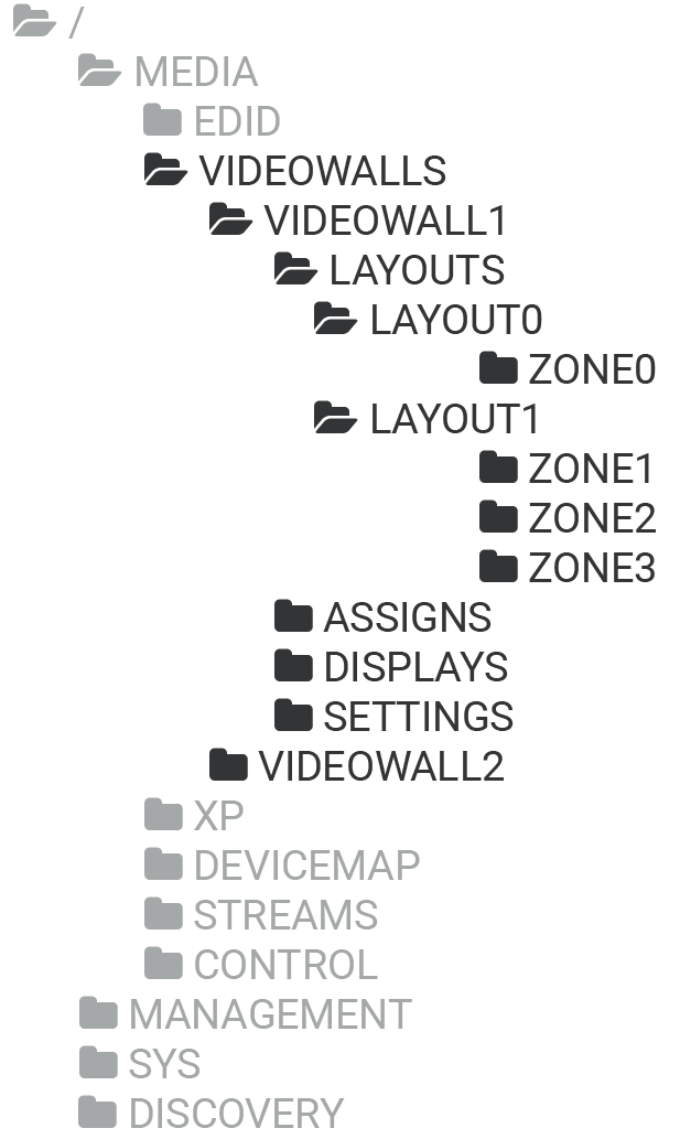
General Description
The path of the video wall related methods and properties is the /MEDIA/VIDEOWALLS. The video wall is an umbrella term, a wall has layout(s) and a layout has zone(s). The display devices can be attached to the zones.
When the first wall is created, the VIDEOWALL1 path including all required methods and properties are created automatically.
The VIDEOWALL# contains the following paths: /LAYOUTS, /ASSIGNS, /DISPLAYS, and /SETTINGS.
Video Wall
The video wall can handle up to 8x4 (column x row) display devices. Up to 20 video walls can be created, up to 9 layouts per video wall, and up to 9 zones per layout.
The video wall has two states: Active of Inactive. The wall can be edited in Inactive state only.
Layouts
A video wall would have more different layouts which are freely configurable by the user except the first layout (LAYOUT0) which is created automatically. The LAYOUT0 contains one zone only (ZONE0) which includes all display devices in the video wall showing one stream.
New layouts (LAYOUT1, LAYOUT2, etc) can be added to the video wall which may contain more zones.
Zones
The layout contains zones which own the display devices. One zone represents a stream on the video wall. All zones have a unique ID which contains information about the video wall, layout, and the zone. For example: Z321, Z as Zone, 3 as Video Wall 3, 2 as Layout 2, and 1 as Zone 1. The ID of the default ZONE0 is Z100.
Displays
The advanced display device parameters can be found under the /DISPLAYS/ALL path. The width, height, bezel sizes, and gap sizes can be customized with the right command.
Command and Response #videowall #vw
»CALL•/MEDIA/VIDEOWALLS:createGridVideoWall(<video_wall_parameters>)
«mO•/MEDIA/VIDEOWALLS:createGridVideoWall=
Parameters
The <video_wall_parameters> includes the following order of settings:
<video_wall_ID>;<column_number>;<row_number>;<horizontal_size>;<vertical_size>;<top_bezel_size>;<bottom_bezel_size>;<left_bezel_size>;<right_bezel_size>;<horizontal_gap_size>;<vertical_gap_size>
|
Parameter |
Description |
|
<video_wall_ID> |
The ID of the video wall. The rule is the following: the ID of the first video wall must be VIDEOWALL1, the next one is VIDEOWALL2, and so on. |
|
<column_number> |
Total number of columns. |
|
<row_number> |
Total number of rows. |
|
<horizontal_size> |
The width of the screen (display area) in mm. |
|
<vertical_size> |
The height of the screen (display area) in mm. |
|
<top_bezel_size> |
Top bezel of the sink device in mm. |
|
<bottom_bezel_size> |
Bottom bezel of the sink device in mm. |
|
<left_bezel_size> |
Left bezel of the sink device in mm. |
|
<right_bezel_size> |
Right bezel of the sink device in mm. |
|
<horizontal_gap_size> |
Horizontal gap between the sink devices in mm. |
|
<vertical_gap_size> |
Vertical gap between the sink devices in mm. |
Example
»CALL /MEDIA/VIDEOWALLS:createGridVideoWall(VIDEOWALL1;3;2;500;300;10;10;10;10;0;0)
«mO MEDIA/VIDEOWALLS:createGridVideoWall=
Explanation
A 3x2 video wall is created where the size of the displays are 500x300 mm, the bezels are 10 mm on all four sides and there is no gap between the displays.
Command and Response
»CALL•/MEDIA/VIDEOWALLS:deleteGridVideoWall(<video_wall_ID>)
«mO•/MEDIA/VIDEOWALLS:deleteGridVideoWall=
Parameters
See the details in the Creating Video Wall section.
Example
»CALL /MEDIA/VIDEOWALLS:deleteGridVideoWall(VIDEOWALL2)
«mO MEDIA/VIDEOWALLS:deleteGridVideoWall=
9.11.4. Setting the Name of the Video Wall
Command and Response
»SET•/MEDIA/VIDEOWALLS/<video_wall_ID>.Name=<name>
«pw•/MEDIA/VIDEOWALLS/<video_wall_ID>.Name=<name>
Parameters
See the details for the <video_wall_ID> parameter in the Creating Video Wall section.
The following characters are allowed in the <name> parameter: non-capital letters (a-z), capital letters (A-Z), numbers (0-9), and special characters ( - . _ ~ : / ? # [ ] @ ! $ & ( ) + = * ).
Example
»SET /MEDIA/VIDEOWALLS/VIDEOWALL1.Name(My_video_wall)
«pw MEDIA/VIDEOWALLS/VIDEOWALL1.Name(My_video_wall)
9.11.5. Querying the Size of the Video Wall
Command and Response
»GET•/MEDIA/VIDEOWALLS/<video_wall_ID>.Size
«pr•/MEDIA/VIDEOWALLS/<video_wall_ID>.Size=<size>
Example
»GET /MEDIA/VIDEOWALLS/VIDEOWALL1.Size
«pr MEDIA/VIDEOWALLS/VIDEOWALL1.Size=5x3
Explanation
The video wall contains 5 columns and 3 rows.
9.11.6. Modifying the Size of the Video Wall
Command and Response
»CALL•/MEDIA/VIDEOWALLS/<video_wall_ID>:modifyVideoWallSize(<column_number>;<row_number>)
«mO•/MEDIA/VIDEOWALLS/<video_wall_ID>:modifyVideoWallSize=
Parameters
See the details in the Creating Video Wall section.
Example
»CALL /MEDIA/VIDEOWALLS/VIDEOWALL1:modifyVideoWallSize(4;3)
«mO MEDIA/VIDEOWALLS/VIDEOWALL1:modifyVideoWallSize=
9.11.7. Assign Outputs to the Video Wall
Command and Response
»CALL•/MEDIA/VIDEOWALLS/<video_wall_ID>/ASSIGNS:assignOutput(<display_ID>:<out>)
«mO•/MEDIA/VIDEOWALLS/<video_wall_ID>/ASSINGS:assignOutput=
Parameters
|
Parameter |
Description |
Formula |
|
<display_ID> |
The ID of the display device in the wall. |
R<row_number>C<column_number> |
|
<out> |
HDMI output 1 port of the RX / TRX |
D<logical_device_ID><out_port_nr> |
The following figure shows the values of the <display_ID> parameter in an 8x4 video wall.
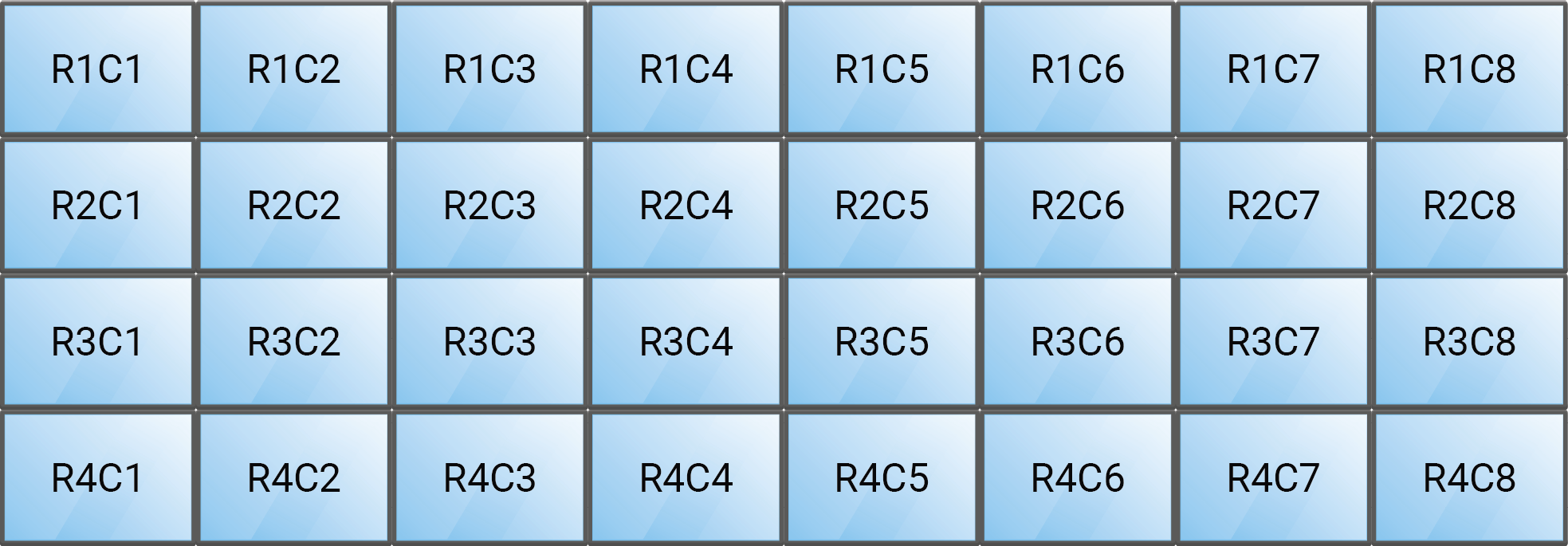
Example
»CALL /MEDIA/VIDEOWALLS/VIDEOWALL1/ASSIGNS:assignOutput(R1C1:D101;R1C2:D201)
«mO MEDIA/VIDEOWALLS/VIDEOWALL1/ASSIGNS:assignOutput=
Command and Response
»CALL•/MEDIA/VIDEOWALLS/<video_wall_ID>/ASSIGNS:unassignOutput(<display_ID>)
«mO•/MEDIA/VIDEOWALLS/<video_wall_ID>/ASSINGS:unassignOutput=
Parameters
See the details in the Assign Outputs to the Video Wall section.
Example
»CALL /MEDIA/VIDEOWALLS/VIDEOWALL1/ASSIGNS:unassignOutput(R1C1;R1C2)
«mO MEDIA/VIDEOWALLS/VIDEOWALL1/ASSIGNS:unassignOutput=
Command and Response
»CALL•/MEDIA/VIDEOWALLS/<video_wall_ID>/ASSIGNS:unassignAllOutput()
«mO•/MEDIA/VIDEOWALLS/<video_wall_ID>/ASSINGS:unassignAllOutput=
Example
»CALL /MEDIA/VIDEOWALLS/VIDEOWALL1/ASSIGNS:unassignAllOutput()
«mO MEDIA/VIDEOWALLS/VIDEOWALL1/ASSIGNS:unassignAllOutput=
9.11.10. Querying an Output Assignment
Command and Response
»GET•/MEDIA/VIDEOWALLS/ASSIGNS/<video_wall_ID>.<display_ID>
«pr•/MEDIA/VIDEOWALLS/ASSIGNS/<video_wall_ID>.<display_ID>=<out>
Parameters
|
Parameter |
Description |
Formula |
|
<video_wall_ID> |
The ID of the video wall. |
VIDEOWALL<number> |
|
<display_ID> |
The ID of the display device in the wall. |
R<row_number>C<column_number> |
|
<out> |
HDMI output 1 port of the RX / TRX |
D<logical_device_ID><out_port_nr> |
Example
»GET /MEDIA/VIDEOWALLS/VIDEOWALL1/ASSIGNS.R1C1
«pr MEDIA/VIDEOWALLS/VIDEOWALL1/ASSIGNS.R1C1=D101
Explanation
The R1C1 sink device displays the stream coming from the D101 output port.
9.11.11. Setting the Background Color of the Video Wall
The video wall background generates an whole-colored image which can be displayed when there is no incoming signal on the video wall or the display devices are not attached to a zone yet. The following method sets the displayed color defined in RGB code.
Command and Response
»SET•/MEDIA/VIDEOWALLS/<video_wall_ID>/SETTINGS.BackgroundColor=<RGB_code>
«pw•/MEDIA/VIDEOWALLS/<video_wall_ID>/SETTINGS.BackgroundColor=<RGB_code>
Example
»SET /MEDIA/VIDEOWALLS/VIDEOWALL1/SETTINGS.BackgroundColor=128;128;128
«pw /MEDIA/VIDEOWALLS/VIDEOWALL1/SETTINGS.BackgroundColor=128;128;128
The timing mode is set with the following command. See more details about it in the Timing Modes section.
Command and Response #timingmode #freerun #sourcelocked
»SET•/MEDIA/VIDEOWALLS/<video_wall_ID>/SETTINGS.TimingMode=<timing_mode>
«pw•/MEDIA/VIDEOWALLS/<video_wall_ID>/SETTINGSTimingMode=<timing_mode>
Parameters
The <timing_mode> can be set to Freerun or SourceLocked.
Example
»SET /MEDIA/VIDEOWALLS/VIDEOWALL1/SETTINGS.TimingMode=SourceLocked
«pw /MEDIA/VIDEOWALLS/VIDEOWALL1/SETTINGS.TimingMode=SourceLocked
9.11.13. Color Space Converter Setting
Command and Response #csc #colorspace
»SET•/MEDIA/VIDEOWALLS/<video_wall_ID>/SETTINGS.ColorSpaceSetting=<color_space>
«pw•/MEDIA/VIDEOWALLS/<video_wall_ID>/SETTINGS.ColorSpaceSetting=<color_space>
Parameters
|
Parameter |
Parameter description |
Value |
Value description |
|
<color_space> |
Color space setting |
Pass |
Pass-through mode - the original color space of the stream is transmitted to the sink device. |
|
RGB |
Forced RGB color space. |
||
|
YCbCr 4:4:4 |
Forced YCbCr 4:4:4 color space. |
||
|
YCbCr 4:2:2 |
Forced YCbCr 4:2:2 color space. |
Example
»SET /MEDIA/VIDEOWALLS/VIDEOWALL1/SETTINGS.ColorSpaceSetting=RGB
«pw /MEDIA/VIDEOWALLS/VIDEOWALL1/SETTINGS.ColorSpaceSetting=RGB
9.11.14. Resolution Mode Setting
Command and Response #scaler #frc
»SET•/MEDIA/VIDEOWALLS/<video_wall_ID>/SETTINGS.ResolutionMode=<resolution_mode>
«pw•/MEDIA/VIDEOWALLS/<video_wall_ID>/SETTINGS.ResolutionMode=<resolution_mode>
Parameters
|
Parameter |
Parameter description |
Value |
Value description |
|
<resolution_mode> |
Resolution mode setting |
Pass |
Pass-through mode - the original stream is transmitted to the sink device. |
|
Forced |
The endpoint device forces the resolution set in the ResolutionSetting for the stream and transmits it to the sink device. |
||
|
EdidBased |
The endpoint device forces the resolution that is read out from the EDID of the connected sink device. |
Example
»SET /MEDIA/VIDEOWALLS/VIDEOWALL1/SETTINGS.ResolutionMode=EdidBased
«pw /MEDIA/VIDEOWALLS/VIDEOWALL1/SETTINGS.ResolutionMode=EdidBased
The resolution that is set here will be enforced only if the ResolutionMode is set to Forced.
Command and Response
»SET•/MEDIA/VIDEOWALLS/<video_wall_ID>/SETTINGS.ResolutionSetting=<resolution>
«pw•/MEDIA/VIDEOWALLS/<video_wall_ID>/SETTINGS.ResolutionSetting=<resolution>
Example
»SET /MEDIA/VIDEOWALLS/VIDEOWALL1/SETTINGS.ResolutionSetting=1920x1080p60
«pw /MEDIA/VIDEOWALLS/VIDEOWALL1/SETTINGS.ResolutionSetting=1920x1080p60
INFO:The entire list of available resolutions can be found in the Resolutions of the Scaler section.
9.11.16. No Sync Screen Setting
Enables or disables the BackgroundColor with the set color of the video wall or the active zone when the wall is in edit state. See the setting of the color in the Setting the Background Color of the Video Wall section.
Command and Response #testpattern #nosyncscreen
»SET•/MEDIA/VIDEOWALLS/<video_wall_ID>/SETTINGS.ForceNoSyncScreen=<logical_value>
«pw•/MEDIA/VIDEOWALLS/<video_wall_ID>/SETTINGS.ForceNoSyncScreen=<logical_value>
Parameters
|
Parameter |
Parameter description |
Value |
Value description |
|
<logical_value> |
Enables or disables the BackgroundColor with the set color of the video wall or the active zone when the wall is in edit state. |
true |
No sync screen is enabled, the displays shows the color which are set in the BackgroundColor property. |
|
false |
No sync screen is disabled, the displays shows the active video stream. |
Example
»SET /MEDIA/VIDEOWALLS/VIDEOWALL1/SETTINGS.ForceNoSyncScreen=true
«pw /MEDIA/VIDEOWALLS/VIDEOWALL1/SETTINGS.ForceNoSyncScreen=true
9.11.17. Query the Display Parameters
The query returns with the set parameters of all display devices in the video wall. These parameters are set originally when the video wall is created - see the details in the Creating Video Wall section.
Command and Response
»GET•/MEDIA/VIDEOWALLS/<video_wall_ID>/DISPLAYS.All
«pr•/MEDIA/VIDEOWALLS/<video_wall_ID>/DISPLAYS.All=<display_parameters>
Parameters
The <display_parameters> includes the following order of settings:
<horizontal_size>;<vertical_size>;<top_bezel_size>;<bottom_bezel_size>;<left_bezel_size>;<right_bezel_size>;<horizontal_gap_size>;<vertical_gap_size>
|
Parameter |
Description |
|
<horizontal_size> |
The width of the screen (display area) in mm. |
|
<vertical_size> |
The height of the screen (display area) in mm. |
|
<top_bezel_size> |
Top bezel of the sink device in mm. |
|
<bottom_bezel_size> |
Bottom bezel of the sink device in mm. |
|
<left_bezel_size> |
Left bezel of the sink device in mm. |
|
<right_bezel_size> |
Right bezel of the sink device in mm. |
|
<horizontal_gap_size> |
Horizontal gap between the sink devices in mm. |
|
<vertical_gap_size> |
Vertical gap between the sink devices in mm. |
Example
»GET /MEDIA/VIDEOWALLS/VIDEOWALL1/DISPLAYS.All
«pr /MEDIA/VIDEOWALLS/VIDEOWALL1/DISPLAYS.All=500;300;10;10;10;10;0;0
9.11.18. Change the Width of the Display
Command and Response
»SET•/MEDIA/VIDEOWALLS/<video_wall_ID>/DISPLAYS/ALL.Width=<horizontal_size>
«pw•/MEDIA/VIDEOWALLS/<video_wall_ID>/DISPLAYS/ALL.Width=<horizontal_size>
Example
»SET /MEDIA/VIDEOWALLS/VIDEOWALL1/DISPLAYS/ALL.Width=657
«pw /MEDIA/VIDEOWALLS/VIDEOWALL1/DISPLAYS/ALL.Width=657
9.11.19. Change the Height of the Display
Command and Response
»SET•/MEDIA/VIDEOWALLS/<video_wall_ID>/DISPLAYS/ALL.Height=<vertical_size>
«pw•/MEDIA/VIDEOWALLS/<video_wall_ID>/DISPLAYS/ALL.Height=<vertical_size>
Example
»SET /MEDIA/VIDEOWALLS/VIDEOWALL1/DISPLAYS/ALL.Width=333
«pw /MEDIA/VIDEOWALLS/VIDEOWALL1/DISPLAYS/ALL.Width=333
9.11.20. Change the Top Bezel Size of the Display
Command and Response
»SET•/MEDIA/VIDEOWALLS/<video_wall_ID>/DISPLAYS/ALL.TopBezelSize=<top_bezel_size>
«pw•/MEDIA/VIDEOWALLS/<video_wall_ID>/DISPLAYS/ALL.TopBezelSize=<top_bezel_size>
Example
»SET /MEDIA/VIDEOWALLS/VIDEOWALL1/DISPLAYS/ALL.TopBezelSize=5
«pw /MEDIA/VIDEOWALLS/VIDEOWALL1/DISPLAYS/ALL.TopBezelSize=5
9.11.21. Change the Bottom Bezel Size of the Display
Command and Response
»SET•/MEDIA/VIDEOWALLS/<video_wall_ID>/DISPLAYS/ALL.BottomBezelSize=<bottom_bezel_size>
«pw•/MEDIA/VIDEOWALLS/<video_wall_ID>/DISPLAYS/ALL.BottomBezelSize=<bottom_bezel_size>
Example
»SET /MEDIA/VIDEOWALLS/VIDEOWALL1/DISPLAYS/ALL.BottomBezelSize=5
«pw /MEDIA/VIDEOWALLS/VIDEOWALL1/DISPLAYS/ALL.BottomBezelSize=5
9.11.22. Change the Left Bezel Size of the Display
Command and Response
»SET•/MEDIA/VIDEOWALLS/<video_wall_ID>/DISPLAYS/ALL.LeftBezelSize=<left_bezel_size>
«pw•/MEDIA/VIDEOWALLS/<video_wall_ID>/DISPLAYS/ALL.LeftBezelSize=<left_bezel_size>
Example
»SET /MEDIA/VIDEOWALLS/VIDEOWALL1/DISPLAYS/ALL.LeftBezelSize=5
«pw /MEDIA/VIDEOWALLS/VIDEOWALL1/DISPLAYS/ALL.LeftBezelSize=5
9.11.23. Change the Right Bezel Size of the Display
Command and Response
»SET•/MEDIA/VIDEOWALLS/<video_wall_ID>/DISPLAYS/ALL.RightBezelSize=<right_bezel_size>
«pw•/MEDIA/VIDEOWALLS/<video_wall_ID>/DISPLAYS/ALL.RightBezelSize=<right_bezel_size>
Example
»SET /MEDIA/VIDEOWALLS/VIDEOWALL1/DISPLAYS/ALL.RightBezelSize=5
«pw /MEDIA/VIDEOWALLS/VIDEOWALL1/DISPLAYS/ALL.RightBezelSize=5
9.11.24. Change the Horizontal Gap Size
Command and Response
»SET•/MEDIA/VIDEOWALLS/<video_wall_ID>/DISPLAYS/ALL.HorizontalGapSize=<horizontal_gap_size>
«pw•/MEDIA/VIDEOWALLS/<video_wall_ID>/DISPLAYS/ALL.HorizontalGapSize=<horizontal_gap_size>
Example
»SET /MEDIA/VIDEOWALLS/VIDEOWALL1/DISPLAYS/ALL.HorizontalGapSize=1
«pw /MEDIA/VIDEOWALLS/VIDEOWALL1/DISPLAYS/ALL.HorizontalGapSize=1
9.11.25. Change the Vertical Gap Size
Command and Response
»SET•/MEDIA/VIDEOWALLS/<video_wall_ID>/DISPLAYS/ALL.VerticalGapSize=<vertical_gap_size>
«pw•/MEDIA/VIDEOWALLS/<video_wall_ID>/DISPLAYS/ALL.VerticalGapSize=<vertical_gap_size>
Example
»SET /MEDIA/VIDEOWALLS/VIDEOWALL1/DISPLAYS/ALL.VerticalGapSize=1
«pw /MEDIA/VIDEOWALLS/VIDEOWALL1/DISPLAYS/ALL.VerticalGapSize=1
9.11.26. Querying the State of the Video Wall
Activity state of the video wall. The wall can be edited in Inactive state only.
Command and Response
»GET•/MEDIA/VIDEOWALLS/<video_wall_ID>.State
«pr•/MEDIA/VIDEOWALLS/<video_wall_ID>.State=<state>
Parameters
|
Parameter |
Parameter description |
Value |
Value description |
|
<state> |
Activity state of the video wall |
Active |
The video wall is active. |
|
Inactive |
The video wall is inactive and configurable. |
Example
»SET /MEDIA/VIDEOWALLS/VIDEOWALL1.State
«pw /MEDIA/VIDEOWALLS/VIDEOWALL1.State=Inactive
9.11.27. Setting the State of the Video Wall
Setting of the activity state. The video wall can be edited in Inactive state only.
Command and Response
»CALL•/MEDIA/VIDEOWALLS/<video_wall_ID>:setState(<state>)
«mO•/MEDIA/VIDEOWALLS/<video_wall_ID>:setState
Parameters
See the details in the previous section.
Example
»CALL /MEDIA/VIDEOWALLS/VIDEOWALL1:setState=Active
«mO /MEDIA/VIDEOWALLS/VIDEOWALL1:setState
9.11.28. Identify the Video Wall
Calling the method generates 10 test colors on the display devices for 10 seconds. The feature helps to identify the video wall physically.
Command and Response
»CALL•/MEDIA/VIDEOWALLS/<video_wall_ID>:identifyVideoWall()
«mO•/MEDIA/VIDEOWALLS/<video_wall_ID>:identifyVideoWall
Example
»CALL /MEDIA/VIDEOWALLS/VIDEOWALL1:identifyVideoWall()
«mO /MEDIA/VIDEOWALLS/VIDEOWALL1:identifyVideoWall
Explanation
9.11.29. Creating a New Layout
INFO:When a new video wall is created, a default layout (LAYOUT0) is also defined automatically. The default layout cannot be deleted (only with deleting the video wall together) and has one zone only (ZONE0) which contains all display devices in the video wall.
Command and Response #layout
»CALL•/MEDIA/VIDEOWALLS/<video_wall_ID>/LAYOUTS:createLayout(<layout_ID>;<name>)
«mO•/MEDIA/VIDEOWALLS/<video_wall_ID>/LAYOUTS:createLayout
Parameters
|
Parameter |
Description |
Formula |
|
<layout_ID> |
The ID of the layout. |
LAYOUT<number> |
|
<name> |
The unique name of the layout given by the user. |
The following characters are allowed in the <name> parameter: non-capital letters (a-z), capital letters (A-Z), numbers (0-9), and special characters ( - . _ ~ : / ? # [ ] @ ! $ & ( ) + = * ). |
Example
»CALL /MEDIA/VIDEOWALLS/VIDEOWALL1/LAYOUTS:createLayout(LAYOUT1;My_Layout)
«mO /MEDIA/VIDEOWALLS/VIDEOWALL1/LAYOUTS:createLayout
Command and Response
»CALL•/MEDIA/VIDEOWALLS/<video_wall_ID>/LAYOUTS:deleteLayout(<layout_ID>)
«mO•/MEDIA/VIDEOWALLS/<video_wall_ID>/LAYOUTS:deleteLayout
Example
»CALL /MEDIA/VIDEOWALLS/VIDEOWALL1/LAYOUTS:deleteLayout(LAYOUT1)
«mO /MEDIA/VIDEOWALLS/VIDEOWALL1/LAYOUTS:deleteLayout
Command and Response
»CALL•/MEDIA/VIDEOWALLS/<video_wall_ID>/LAYOUTS:deleteAllLayout()
«mO•/MEDIA/VIDEOWALLS/<video_wall_ID>/LAYOUTS:deleteAllLayout
Example
»CALL /MEDIA/VIDEOWALLS/VIDEOWALL1/LAYOUTS:deleteAllLayout()
«mO /MEDIA/VIDEOWALLS/VIDEOWALL1/LAYOUTS:deleteAllLayout
9.11.32. Querying the Active Layout
Command and Response
»GET•/MEDIA/VIDEOWALLS/<video_wall_ID>/LAYOUTS.activeLayout
«pr•/MEDIA/VIDEOWALLS/<video_wall_ID>/LAYOUTS.activeLayout=<layout_ID>
Example
»GET /MEDIA/VIDEOWALLS/VIDEOWALL1/LAYOUTS.activeLayout
«pr /MEDIA/VIDEOWALLS/VIDEOWALL1/LAYOUTS.activeLayout=LAYOUT0
Command and Response
»CALL•/MEDIA/VIDEOWALLS/<video_wall_ID>/LAYOUTS.activateLayout(<layout_ID>)
«mO•/MEDIA/VIDEOWALLS/<video_wall_ID>/LAYOUTS.activateLayout
Example
»CALL /MEDIA/VIDEOWALLS/VIDEOWALL1/LAYOUTS.activateLayout(LAYOUT1)
«pr /MEDIA/VIDEOWALLS/VIDEOWALL1/LAYOUTS.activateLayout
9.11.34. Setting the Name of the Layout
Command and Response
»SET•/MEDIA/VIDEOWALLS/<video_wall_ID>/LAYOUTS/<layout_ID>.Name=<name>
«pw•/MEDIA/VIDEOWALLS/<video_wall_ID>/LAYOUTS/<layout_ID>.Name=<name>
Parameters
The following characters are allowed in the <name> parameter: non-capital letters (a-z), capital letters (A-Z), numbers (0-9), and special characters ( - . _ ~ : / ? # [ ] @ ! $ & ( ) + = * ).
Example
»SET /MEDIA/VIDEOWALLS/VIDEOWALL1/LAYOUTS/LAYOUT1.Name=My_Layout
«pw /MEDIA/VIDEOWALLS/VIDEOWALL1/LAYOUTS/LAYOUT1.Name=My_Layout
Calling the method generates 10 test colors on the display devices for 10 seconds. The feature helps to identify the layout physically.
Command and Response
»CALL•/MEDIA/VIDEOWALLS/<video_wall_ID>/LAYOUTS/<layout_ID>:identifyLayout()
«mO•/MEDIA/VIDEOWALLS/<video_wall_ID>/LAYOUTS/<layout_ID>:identifyLayout
Example
»CALL /MEDIA/VIDEOWALLS/VIDEOWALL1/LAYOUTS/LAYOUT1:identifyLayout()
«mO /MEDIA/VIDEOWALLS/VIDEOWALL1/LAYOUTS/LAYOUT1:identifyLayout
Explanation
A layout can contain more zones where the displayed source stream are different.
Command and Response #zone
»CALL•/MEDIA/VIDEOWALLS/<video_wall_ID>/LAYOUTS/<layout_ID>:createZone(<zone_ID>;<display_ID>)
«mO•/MEDIA/VIDEOWALLS/<video_wall_ID>/LAYOUTS/<layout_ID>:createZone
Parameters
|
Parameter |
Description |
Formula |
|
<zone_ID> |
The ID of the zone |
ZONE<number> |
|
<display_ID> |
The ID of the display device in the wall. |
R<row_number>C<column_number> |
The following figure shows the values of the <display_ID> parameter in an 8x4 video wall.
Example
»CALL /MEDIA/VIDEOWALLS/VIDEOWALL1/LAYOUTS/LAYOUT1:createZone(ZONE1;R1C1;R1C2;R1C3)
«mO /MEDIA/VIDEOWALLS/VIDEOWALL1/LAYOUTS/LAYOUT1:createZone
Command and Response
»CALL•/MEDIA/VIDEOWALLS/<video_wall_ID>/LAYOUTS/<layout_ID>:deleteZone(<zone_ID>)
«mO•/MEDIA/VIDEOWALLS/<video_wall_ID>/LAYOUTS/<layout_ID>:deleteZone=
Example
»CALL /MEDIA/VIDEOWALLS/VIDEOWALL1/LAYOUTS/LAYOUT1:deleteZone(ZONE1)
«mO /MEDIA/VIDEOWALLS/VIDEOWALL1/LAYOUTS/LAYOUT1:deleteZone=
Command and Response
»CALL•/MEDIA/VIDEOWALLS/<video_wall_ID>/LAYOUTS/<layout_ID>:deleteAllZone()
«mO•/MEDIA/VIDEOWALLS/<video_wall_ID>/LAYOUTS/<layout_ID>:deleteAllZone=
Example
»CALL /MEDIA/VIDEOWALLS/VIDEOWALL1/LAYOUTS/LAYOUT1:deleteAllZone()
«mO /MEDIA/VIDEOWALLS/VIDEOWALL1/LAYOUTS/LAYOUT1:deleteAllZone=
9.11.39. Setting the Name of the Zone
Command and Response
»SET•/MEDIA/VIDEOWALLS/<video_wall_ID>/LAYOUTS/<layout_ID>/<zone_ID>.Name=<name>
«pw•/MEDIA/VIDEOWALLS/<video_wall_ID>/LAYOUTS/<layout_ID>/<zone_ID>.Name=<name>
Example
»SET /MEDIA/VIDEOWALLS/VIDEOWALL1/LAYOUTS/LAYOUT1/ZONE1.Name=Big_Zone
«pw /MEDIA/VIDEOWALLS/VIDEOWALL1/LAYOUTS/LAYOUT1/ZONE1.Name=Big_Zone
9.11.40. Querying the Size of the Zone
Command and Response
»GET•/MEDIA/VIDEOWALLS/<video_wall_ID>/LAYOUTS/<layout_ID>/<zone_ID>.ZoneSize
«pr•/MEDIA/VIDEOWALLS/<video_wall_ID>/LAYOUTS/<layout_ID>/<zone_ID>.ZoneSize=<size>
Example
»GET /MEDIA/VIDEOWALLS/VIDEOWALL1/LAYOUTS/LAYOUT1/ZONE1.ZoneSize
«pr /MEDIA/VIDEOWALLS/VIDEOWALL1/LAYOUTS/LAYOUT1/ZONE1.ZoneSize=1x3
Explanation
The ZONE1 zone contains 1 column and 3 rows.
Calling the method generates 10 test colors on the display devices for 10 seconds. The feature helps to identify the zone physically.
Command and Response
»CALL•/MEDIA/VIDEOWALLS/<video_wall_ID>/LAYOUTS/<layout_ID>/<zone_ID>:identifyZone()
«mO•/MEDIA/VIDEOWALLS/<video_wall_ID>/LAYOUTS/<layout_ID>/<zone_ID>:identifyZone
Example
»CALL /MEDIA/VIDEOWALLS/VIDEOWALL1/LAYOUTS/LAYOUT1/ZONE1:identifyZone()
«mO /MEDIA/VIDEOWALLS/VIDEOWALL1/LAYOUTS/LAYOUT1/ZONE1:identifyZone
Explanation
9.11.42. Setting the Background Color of the Zone
The zone background generates an whole-colored image which can be displayed when there is no incoming signal on the zone. The following method sets the displayed color defined in RGB code.
Command and Response
»SET•/MEDIA/VIDEOWALLS/<video_wall_ID>/LAYOUTS/<layout_ID>/<zone_ID>.BackgroundColor=<RGB_code>
«pw•/MEDIA/VIDEOWALLS/<video_wall_ID>/LAYOUTS/<layout_ID>/<zone_ID>.BackgroundColor=<RGB_code>
Example
»SET /MEDIA/VIDEOWALLS/VIDEOWALL1/LAYOUTS/LAYOUT1/ZONE1.BackgroundColor=128;128;128
«pw /MEDIA/VIDEOWALLS/VIDEOWALL1/LAYOUTS/LAYOUT1/ZONE1.BackgroundColor=128;128;128
9.11.43. Assign Display to the Zone
Command and Response
»CALL•/MEDIA/VIDEOWALLS/<video_wall_ID>/LAYOUTS/<layout_ID>/<zone_ID>:assignDisplay(<display_ID>)
«mO•/MEDIA/VIDEOWALLS/<video_wall_ID>/LAYOUTS/<layout_ID>/<zone_ID>:assignDisplay
Example
»CALL /MEDIA/VIDEOWALLS/VIDEOWALL1/LAYOUTS/LAYOUT1/ZONE1:assignDisplay(R1C1;R2C1)
«mO /MEDIA/VIDEOWALLS/VIDEOWALL1/LAYOUTS/LAYOUT1/ZONE1:assignDisplay
9.11.44. Unassign Display from the Zone
Command and Response
»CALL•/MEDIA/VIDEOWALLS/<video_wall_ID>/LAYOUTS/<layout_ID>/<zone_ID>:unassignDisplay(<display_ID>)
«mO•/MEDIA/VIDEOWALLS/<video_wall_ID>/LAYOUTS/<layout_ID>/<zone_ID>:unassignDisplay
Example
»CALL /MEDIA/VIDEOWALLS/VIDEOWALL1/LAYOUTS/LAYOUT1/ZONE1:unassignDisplay(R1C1;R2C1)
«mO /MEDIA/VIDEOWALLS/VIDEOWALL1/LAYOUTS/LAYOUT1/ZONE1:unassignDisplay
9.11.45. Unassign All Displays from the Zone
Command and Response
»CALL•/MEDIA/VIDEOWALLS/<video_wall_ID>/LAYOUTS/<layout_ID>/<zone_ID>:unassignAllDisplay()
«mO•/MEDIA/VIDEOWALLS/<video_wall_ID>/LAYOUTS/<layout_ID>/<zone_ID>:unassignAllDisplay
Example
»CALL /MEDIA/VIDEOWALLS/VIDEOWALL1/LAYOUTS/LAYOUT1/ZONE1:unassignAllDisplay()
«mO /MEDIA/VIDEOWALLS/VIDEOWALL1/LAYOUTS/LAYOUT1/ZONE1:unassignAllDisplay
9.11.46. Query the Tags of the Zone
The query returns with the tags which are added by the user.
Command and Response
»GET•/MEDIA/VIDEOWALLS/<video_wall_ID>/LAYOUTS/<layout_ID>/<zone_ID>.Tags
«pr•/MEDIA/VIDEOWALLS/<video_wall_ID>/LAYOUTS/<layout_ID>/<zone_ID>.Tags=<tag>
Example
»GET /MEDIA/VIDEOWALLS/VIDEOWALL1/LAYOUTS/LAYOUT1/ZONE1.Tags
«pr /MEDIA/VIDEOWALLS/VIDEOWALL1/LAYOUTS/LAYOUT1/ZONE1.Tags=1080p;intro
#tag
9.11.47. Adding Tags to the Zone
The following characters are allowed in the <tag> parameter: non-capital letters (a-z), capital letters (A-Z), numbers (0-9), and special characters ( - . _ ~ : / ? # [ ] @ ! $ & ( ) + = * ).
Command and Response
»CALL•/MEDIA/VIDEOWALLS/<video_wall_ID>/LAYOUTS/<layout_ID>/<zone_ID>:addTags(<tag>)
«mO•/MEDIA/VIDEOWALLS/<video_wall_ID>/LAYOUTS/<layout_ID>/<zone_ID>:addTags
Example
»CALL /MEDIA/VIDEOWALLS/VIDEOWALL1/LAYOUTS/LAYOUT1/ZONE1:addTags(1080p;intro)
«mO /MEDIA/VIDEOWALLS/VIDEOWALL1/LAYOUTS/LAYOUT1/ZONE1:addTags
9.11.48. Deleting Tags of the Zone
Command and Response
»CALL•/MEDIA/VIDEOWALLS/<video_wall_ID>/LAYOUTS/<layout_ID>/<zone_ID>:removeTags(<tag>)
«mO•/MEDIA/VIDEOWALLS/<video_wall_ID>/LAYOUTS/<layout_ID>/<zone_ID>:removeTags
Example
»CALL /MEDIA/VIDEOWALLS/VIDEOWALL1/LAYOUTS/LAYOUT1/ZONE1:removeTags(cartoon;1080p)
«mO /MEDIA/VIDEOWALLS/VIDEOWALL1/LAYOUTS/LAYOUT1/ZONE1:removeTags
9.11.49. Deleting All Tags of the Zone
Command and Response
»CALL•/MEDIA/VIDEOWALLS/<video_wall_ID>/LAYOUTS/<layout_ID>/<zone_ID>:removeAllTags()
«mO•/MEDIA/VIDEOWALLS/<video_wall_ID>/LAYOUTS/<layout_ID>/<zone_ID>:removeAllTags
Example
»CALL /MEDIA/VIDEOWALLS/VIDEOWALL1/LAYOUTS/LAYOUT1/ZONE1:removeAllTags()
«mO /MEDIA/VIDEOWALLS/VIDEOWALL1/LAYOUTS/LAYOUT1/ZONE1:removeAllTags
9.11.50. Query the Static Tags of the Zone
The query returns with all the tags which belong to the video wall. These tags are reserved.
Command and Response
»GET•/MEDIA/VIDEOWALLS/<video_wall_ID>/LAYOUTS/<layout_ID>/<zone_ID>.StaticTags
«pr•/MEDIA/VIDEOWALLS/<video_wall_ID>/LAYOUTS/<layout_ID>/<zone_ID>.StaticTags=<tag>
Example
»GET /MEDIA/VIDEOWALLS/VIDEOWALL1/LAYOUTS/LAYOUT1/ZONE1.StaticTags
«pr /MEDIA/VIDEOWALLS/VIDEOWALL1/LAYOUTS/LAYOUT1/ZONE1.StaticTags=VideoWall1;Z121
9.11.51. Switching the Video Stream to the Video Wall Zone
Command and Response #switch #crosspoint
»CALL•/MEDIA/XP/VIDEO:switch(<in>:<zone_ID>)
«mO•/MEDIA/XP/VIDEO:switch
Example
»CALL /MEDIA/XP/VIDEO:switch(S501:Z111;S101:Z112;S302:Z113)
«mO /MEDIA/XP/VIDEO:switch
9.12. Multiviewer Configuration
DIFFERENCE:The multiviewer operation mode for the endpoint devices is available only from endpoint firmware package v3.2.0 without MMU support. The MMU support is available from MMU firmware package v2.2.0 which includes the endpoint firmware package v3.3.1 for the centralized firmware update.
Learn more details about the functions and rules of the multiviewer mode in the Multiviewer Mode section. #multiviewer #rxmv
9.12.1. Setting the Resolution of the Canvas
The ResolutionMode is fixed to Forced and cannot be changed in case of multiviewer mode. This setting is equal to the resolution of the sink device and the resolution of the canvas as well. #canvas

Command and Response
»SET• /MEDIA/STREAMS/VIDEO/<out>/PORT.ResolutionSetting=<resolution>
«pw•/MEDIA/STREAMS/VIDEO/<out>/PORT.ResolutionSetting=<resolution>
Example
»SET /MEDIA/STREAMS/VIDEO/D101/PORT.ResolutionSetting=3840x2160p60
«pw /MEDIA/STREAMS/VIDEO/D101/PORT.ResolutionSetting=3840x2160p60
INFO:The entire list of available resolutions can be found in the Resolutions of the Scaler section.
9.12.2. Enabling/Disabling the Tile
The tile in the canvas can be enabled or disabled.
There are four tile properties (T1; T2; T3; T4) under the O1 port, that can be accessed in the Matrix application mode. #tile

Command and Response
»SET•/MEDIA/STREAMS/VIDEO/<out>/PORT/<tile>.Enabled=<logical_value>
«pw•/MEDIA/STREAMS/VIDEO/<out>/PORT/<tile>.Enabled=<logical_value>
Parameters
|
Parameter |
Parameter description |
Value |
Value description |
|
<logical_value> |
The stream is unmuted or muted. |
true |
The stream is enabled (unmuted). |
|
false |
The stream is disabled (muted). |
||
|
<tile> |
Tile ID |
T1 |
The ID of Tile #1. |
|
T2 |
The ID of Tile #2. |
||
|
T3 |
The ID of Tile #3. |
||
|
T4 |
The ID of Tile #4. |
Example
»SET /MEDIA/STREAMS/VIDEO/D101/PORT/T1.Enabled=false
«pw /MEDIA/STREAMS/VIDEO/D101/PORT/T1.Enabled=false

The position of the tile inside the canvas can be set with the property. The top left corner of the tile is the starter pixel, the required parameters are the horizontal and vertical pixels.
ATTENTION!In case of picture-in-picture mode, the position of the background tile shall be 0, 0.
ATTENTION!Tiles must be placed within the canvas area, extending beyond the canvas is not supported.
Command and Response
»SET•/MEDIA/STREAMS/VIDEO/<out>/PORT/<tile>.Position=<horizontal_pixels>,<vertical_pixels>
«pw•/MEDIA/STREAMS/VIDEO/<out>/PORT/<tile>.Position=<horizontal_pixels>,<vertical_pixels>
Parameters
|
Parameter |
Parameter description |
Value |
Value description |
|
<tile> |
Tile ID |
T1 |
The ID of Tile #1. |
|
T2 |
The ID of Tile #2. |
||
|
T3 |
The ID of Tile #3. |
||
|
T4 |
The ID of Tile #4. |
Example
»SET /MEDIA/STREAMS/VIDEO/D101/PORT/T1.Position=200,300
«pw /MEDIA/STREAMS/VIDEO/D101/PORT/T1.Position=200,300
The resolution of the tile inside the canvas can be set with the property. #tile
ATTENTION!The tile size and the resolution of the input stream must be the same. See the scaler resolution setting on the transmitter side in the Tile Resolution Setting section.
ATTENTION!Tiles must be placed within the canvas area, extending beyond the canvas is not supported.

Command and Response
»SET•/MEDIA/STREAMS/VIDEO/<out>/PORT/<tile>.Size=<horizontal_pixels>x<vertical_pixels>
«pw•/MEDIA/STREAMS/VIDEO/<out>/PORT/<tile>.Size=<horizontal_pixels>x<vertical_pixels>
Parameters
|
Parameter |
Parameter description |
Value |
Value description |
|
<tile> |
Tile ID |
T1 |
The ID of Tile #1. |
|
T2 |
The ID of Tile #2. |
||
|
T3 |
The ID of Tile #3. |
||
|
T4 |
The ID of Tile #4. |
Example
»SET /MEDIA/STREAMS/VIDEO/D101/PORT/T2.Size=1280x720
«pw /MEDIA/STREAMS/VIDEO/D101/PORT/T2.Size=1280x720
The command is for re-prioritization the tile layouts that can be used in case of the tiles overlap each other. The priority of the tiles determines which is in front.

Command and Response
»SET•/MEDIA/STREAMS/VIDEO/<out>/PORT.LayerOrder=<tile_ID>;<tile_ID>;<tile_ID>;<tile_ID>
«pw•/MEDIA/STREAMS/VIDEO/<out>/PORT.LayerOrder=<tile_ID>;<tile_ID>;<tile_ID>;<tile_ID>
Parameters
|
Parameter |
Parameter description |
Value |
Value description |
|
<tile> |
Tile ID |
1 |
The ID of Tile #1. |
|
2 |
The ID of Tile #2. |
||
|
3 |
The ID of Tile #3. |
||
|
4 |
The ID of Tile #4. |
Example
»SET /MEDIA/STREAMS/VIDEO/D101/PORT.LayerOrder=3;4;1;2
«pw /MEDIA/STREAMS/VIDEO/D101/PORT.LayerOrder=3;4;1;2
The setting adjusts the opacity of the selected tile. The opacity is in percent, 100% means the stream is not transparent, 0% means the stream is not visible. #tile
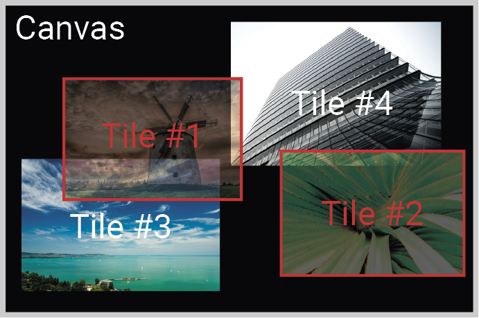
Command and Response
»SET•/MEDIA/STREAMS/VIDEO/<out>/PORT/<tile>.Opacity=<percent>
«pw•/MEDIA/STREAMS/VIDEO/<out>/PORT/<tile>.Opacity=<percent>
Example
»SET /MEDIA/STREAMS/VIDEO/D101/PORT/T1.Opacity=50
«pw /MEDIA/STREAMS/VIDEO/D101/PORT/T1.Opacity=50
Command and Response #colordepth
»SET•/MEDIA/STREAMS/VIDEO/<out>/PORT.ColorDepthSetting=<color_depth>
«pw•/MEDIA/STREAMS/VIDEO/<out>/PORT.ColorDepthSetting=<color_depth>
Parameters
|
Parameter |
Parameter description |
Value |
Value description |
|
<color_depth> |
Color depth setting |
Pass |
No color depth conversion |
|
8 bpc |
Color depth is 8 bit/channel |
||
|
10 bpc |
Color depth is 10 bit/channel |
||
|
12 bpc |
Color depth is 12 bit/channel |
Example
»SET /MEDIA/STREAMS/VIDEO/D101/PORT.ColorDepthSetting=8 bpc
«pw /MEDIA/STREAMS/VIDEO/D101/PORT.ColorDepthSetting=8 bpc
9.12.8. Querying the Status of the Tile
The query returns the actual status of the selected tile.
Command and Response
»GET•/MEDIA/STREAMS/VIDEO/<out>/PORT/<tile>.Status=<status>
«pr•/MEDIA/STREAMS/VIDEO/<out>/PORT/<tile>.Status=<status>
Parameters
|
Parameter |
Parameter description |
Value |
Value description |
|
<status> |
Actual status of the tile |
Disabled |
The tile is muted. See the Enabling/Disabling the Tile section to unmute it. |
|
HdcpError |
The HDCP authentication is failed. |
||
|
BandwidthError |
The bandwidth of the tile stream exceeds the limit. See more details about the stream optimalization in the Multiview Designer - Tutorial section and about the bandwidth limits in the Bandwidth Requirements of the Resolutions section. |
||
|
NoInput |
There is no input stream for the tile. |
||
|
InvalidLayout |
The tile is beyond the canvas. Check the position (Tile Position Setting) and the resolution (Tile Size Setting) of the tile to solve this issue. |
||
|
InvalidSize |
The resolution of the input stream and the size of the tile is not equal. |
||
|
InvalidColorFormat |
The color format of the input stream and the color format of the tile is not equal. UBEX multiviewer supports RGB color space only. Color space conversion on the source side is available in the Color Space Converter Setting section. |
||
|
Ok |
The input stream is displayed in the tile correctly. |
Example
»GET /MEDIA/STREAMS/VIDEO/D101/PORT/T2.Status=Ok
«pr /MEDIA/STREAMS/VIDEO/D101/PORT/T2.Status=Ok
9.12.9. No Sync Screen (Test Pattern) Mode
The No sync screen feature generates an image that can be displayed when there is no incoming signal on the port. The following method turns on or off the Test Pattern function.
Command and Response #testpattern #nosyncscreen
»SET•/MEDIA/STREAMS/VIDEO/<out>/PORT.NoSyncMode=<nosync_mode>
«pw•/MEDIA/STREAMS/VIDEO/<out>/PORT. NoSyncMode=<nosync_mode>
Parameters
|
Parameter |
Parameter description |
Value |
Value description |
|
<nosync_mode> |
Test pattern mode setting |
AlwaysOff |
The test pattern is not displayed on the output. |
|
NoSignal |
The test pattern is displayed if there is no video is received on the output port. |
||
|
AlwaysOn |
The test pattern is displayed on the output even if there is an incoming signal. |
||
|
Freeze |
The signal freezes at the last video frame on the sink device (the sink may show a broken frame too). |
Example
»SET /MEDIA/STREAMS/VIDEO/D101/PORT.NoSyncMode=NoSignal
«pw /MEDIA/STREAMS/VIDEO/D101/PORT.NoSyncMode=NoSignal
9.12.10. No Sync Screen (Test Pattern) Color Setting
The No sync screen feature generates an image that can be displayed when there is no incoming signal on the port. The following method sets the displayed color defined in RGB code.
Command and Response
»SET•/MEDIA/STREAMS/VIDEO/<out>/PORT.NoSyncColor=<RGB_code>
«pw•/MEDIA/STREAMS/VIDEO/<out>/PORT. NoSyncColor=<RGB_code>
Example
»SET /MEDIA/STREAMS/VIDEO/D101/PORT.NoSyncColor=128,128,128
«pw /MEDIA/STREAMS/VIDEO/D101/PORT.NoSyncColor=128,128,128
HDCP capability can be set to Auto/Always on the output ports, thus non-encrypted content can be transmitted to a non-HDCP compliant display. See more information in the HDCP Management section.
Command and Response #hdcp
»SET•/MEDIA/STREAMS/VIDEO/<out>/PORT.HdcpMode=<HDCP_mode>
«pw•/MEDIA/STREAMS/VIDEO/<out>/PORT.HdcpMode=<HDCP_mode>
Parameters
|
Parameter |
Parameter description |
Value |
Value description |
|
<HDCP_mode> |
HDCP mode |
Auto |
The level of the HDCP-encryption depends on the input. |
|
Always |
The output ports set the maximum HDCP-encryption level that can be accepted by the connected sink device. |
||
|
AlwaysType1 |
The output ports always force HDCP 2.2 Type 1. If the sink device supports this HDCP-encryption level, the signal will be encrypted with HDCP 2.2 Type 0/1. The signal will be encrypted with HDCP 2.2 Type 1 when the source and the sink both support this HDCP-encryption level. |
Example
»SET /MEDIA/STREAMS/VIDEO/D101/PORT.HdcpMode=AlwaysType1
«pw /MEDIA/STREAMS/VIDEO/D101/PORT.HdcpMode=AlwaysType1
9.12.12. Identify Stream / Identify Display
Calling the method generates 10 test colors on the display device for 10 seconds. The feature helps to identify the stream and the screen itself physically.
Command and Response #identifystream #identifydisplay
»CALL•/MEDIA/STREAMS/VIDEO/<out>/PORT:identify()
«mO•/MEDIA/STREAMS/VIDEO/<out>/PORT:identify
Example
»CALL /MEDIA/STREAMS/VIDEO/D101/PORT:identify()
«mO /MEDIA/STREAMS/VIDEO/D101/PORT:identify
Explanation
9.12.13. Querying the Source MUX Options
The source multiplexer (Source MUX) makes routing several different source signals to the HDMI output ports available. See more details about this function in the Port Diagram section.
The query responds the available source signals for the selected output port.
Command and Response #mux #sourcemux
»GET•/MEDIA/STREAMS/VIDEO/<out>/PORT.SourceMuxOptions
«pr•/MEDIA/STREAMS/VIDEO/<out>/PORT.SourceMuxOptions=<mux_options>
Parameters
|
Parameter |
Parameter description |
Value |
Value description |
|
<mux_options> |
The availabe sources for the output port |
MV1 |
The MV1 (multiviewer) destination stream is selectable for the output port (only for O1). |
|
D5 |
The D5 destination stream is selectable for the output port (only for O2). |
||
|
I1 |
The stream of the I1 local input port is selectable for the output port (only for O1). |
||
|
I2 |
The stream of the I2 local input port is selectable for the output port (only for O2). |
||
|
O1 |
The copy of the stream of O1 output port is selectable for the output port (only for O2). |
Example
»GET /MEDIA/STREAMS/VIDEO/D101/PORT.SourceMuxOptions
«pr /MEDIA/STREAMS/VIDEO/D101/PORT.SourceMuxOptions=I2;O1
The source multiplexer (Source MUX) makes routing several different source signals to the HDMI output ports available. See more details about this function in the Multiviewer Mode section.
The command sets the source signal for the output port. Query the available options with the command described in the previous section.
Command and Response #mux #sourcemux
»SET•/MEDIA/STREAMS/VIDEO/<out>/PORT.SourceMux=<in|out>
«pw•/MEDIA/STREAMS/VIDEO/<out>/PORT.SourceMux=<in|out>
Example
»SET /MEDIA/STREAMS/VIDEO/D101/PORT.SourceMux=O1
«pw /MEDIA/STREAMS/VIDEO/D101/PORT.SourceMux=O1
9.13. Audio Crosspoint Settings
Parameters #audio
|
Parameter |
Description |
Formula |
|
<in> |
Audio stream source ID |
S<logical_devive_ID><stream_nr> |
|
<out> |
Audio destination ID |
D<logical_device_ID><out_port_nr> |
9.13.1. Query the Status of All Audio Ports
The query returns with all information about the source streams and the destinations. The respond contains the following information:
▪Enable/disable status
▪Signal presence
▪Crosspoint status (which stream is connected to the destination port)
▪Source/destination names, tags
▪Device tags
▪Locking status
Command and Response
»GET•/MEDIA/XP/AUDIO/*.*
«pr•/MEDIA/XP/AUDIO/*.*
9.13.2. Switching the Audio Stream to One Destination
Command and Response
»CALL•/MEDIA/XP/AUDIO:switch(<in>:<out>)
«mO•/MEDIA/XP/AUDIO:switch
Example
»CALL /MEDIA/XP/AUDIO:switch(S501:D302;S101:D301)
«mO /MEDIA/XP/AUDIO:switch
9.13.3. Switching an Audio Stream to All Destinations
The selected audio stream is switched to all outputs.
Command and Response
»CALL•/MEDIA/XP/AUDIO:switchAll(<in>)
«mO•/MEDIA/XP/AUDIO:switchAll
Example
»CALL /MEDIA/XP/AUDIO:switchAll(S101)
«mO /MEDIA/XP/AUDIO:switchAll
9.13.4. Query the Number of the Source Ports
The query returns with the number of all source (input) ports including the disabled ones.
Command and Response
»GET•/MEDIA/XP/AUDIO.SourcePortCount
«pr•/MEDIA/XP/AUDIO.SourcePortCount=<number>
Example
»GET /MEDIA/XP/AUDIO.SourcePortCount
«pr /MEDIA/XP/AUDIO.SourcePortCount=36
9.13.5. Query the Number of the Destination Ports
The query returns with the number of all destination (output) ports including the disabled ones.
Command and Response
»GET•/MEDIA/XP/AUDIO.DestinationPortCount
«pr•/MEDIA/XP/AUDIO.DestinationPortCount=<number>
Example
»GET /MEDIA/XP/AUDIO.DestinationPortCount
«pr /MEDIA/XP/AUDIO.DestinationPortCount=36
9.14. Audio Stream Settings
Parameters
|
Parameter |
Description |
Formula |
|
<in> |
Audio stream source ID |
S<logical_devive_ID><stream_nr> |
|
<out> |
Audio destination ID |
D<logical_device_ID><out_port_nr> |
9.14.1. Enable/Disable the Audio Stream Source
Command and Response #streamenable
»SET•/MEDIA/STREAMS/AUDIO/<in>/STREAM.Enabled=<logical_value>
«pw•/MEDIA/STREAMS/AUDIO/<in>/STREAM.Enabled=<logical_value>
Parameters
|
Parameter |
Parameter description |
Value |
Value description |
|
<logical_value> |
The audio stream is unmuted or muted. |
true |
The audio stream is enabled (unmuted). |
|
false |
The audio stream is disabled (muted). |
Example
»SET /MEDIA/STREAMS/AUDIO/I101/STREAM.Enabled=true
«pw /MEDIA/STREAMS/AUDIO/I101/STREAM.Enabled=true
9.14.2. Enable/Disable the Audio Stream Destination
Command and Response
»SET•/MEDIA/STREAMS/AUDIO/<out>/STREAM.Enabled=<logical_value>
«pw•/MEDIA/STREAMS/AUDIO/<out>/STREAM.Enabled=<logical_value>
Parameters
|
Parameter |
Parameter description |
Value |
Value description |
|
<logical_value> |
The audio stream is unmuted or muted. |
true |
The audio stream is enabled (unmuted). |
|
false |
The audio stream is disabled (muted). |
Example
»SET /MEDIA/STREAMS/AUDIO/O101/STREAM.Enabled=true
«pw /MEDIA/STREAMS/AUDIO/O101/STREAM.Enabled=true
9.14.3. Query the Name of the Stream
INFO:The default name of the stream is the MAC address of the endpoint device and the stream number separated by a dot. Example: A8:D2:36:F0:00:03.S1
Command and Response
»GET•/MEDIA/STREAMS/AUDIO/<in>.SourceName
«pw•/MEDIA/STREAMS/AUDIO/<in>.SourceName=<name>
Example
»GET /MEDIA/STREAMS/AUDIO/S2301.SourceName
«pw /MEDIA/STREAMS/AUDIO/S2301.SourceName=Black_Sabbath-Heaven_and_Hell
9.14.4. Setting the Name of the Stream
Command and Response
»SET•/MEDIA/STREAMS/AUDIO/<in>.SourceName=<name>
«pw•/MEDIA/STREAMS/AUDIO/<in>.SourceName=<name>
Example
»SET /MEDIA/STREAMS/AUDIO/S102.SourceName=Celine_Dion-My_Heart_Will_Go_On
«pw /MEDIA/STREAMS/AUDIO/S102.SourceName=Celine_Dion-My_Heart_Will_Go_On
9.14.5. Query the Name of the Destination
INFO:The default name of the destination is the MAC address of the endpoint device and the port number separated by a dot. Example: A8:D2:36:F0:00:03.D1
Command and Response
»GET•/MEDIA/STREAMS/AUDIO/<out>.DestinationName
«pw•/MEDIA/STREAMS/AUDIO/<out>.DestinationName=<name>
Example
»GET /MEDIA/STREAMS/AUDIO/D2301.DestinationName
«pw /MEDIA/STREAMS/AUDIO/D2301.DestinationName=Audio_amplifier
9.14.6. Setting the Name of the Destination
Command and Response
»SET•/MEDIA/STREAMS/AUDIO/<out>.DestinationName=<name>
«pw•/MEDIA/STREAMS/AUDIO/<out>.DestinationName=<name>
Example
»SET /MEDIA/STREAMS/AUDIO/D102.DestinationName=My_small_black_speakers
«pw /MEDIA/STREAMS/AUDIO/D102.DestinationName=My_small_black_speakers
9.14.7. Query the Tags of the Stream/Destination
The query returns with the tags which are added by the user.
Command and Response #tag
»GET•/MEDIA/STREAMS/AUDIO/<in|out>.Tags
«pr•/MEDIA/STREAMS/AUDIO/<in|out>.Tags=<tag>
Example
»GET /MEDIA/STREAMS/AUDIO/S102.Tags
«pr /MEDIA/STREAMS/AUDIO/S102.Tags=PCM;soundtrack;Die_Hard_2
9.14.8. Adding Tags to the Stream/Destination
The following characters are allowed in the <tag> parameter: non-capital letters (a-z), capital letters (A-Z), numbers (0-9), and special characters ( - . _ ~ : / ? # [ ] @ ! $ & ( ) + = * ).
Command and Response
»CALL•/MEDIA/STREAMS/AUDIO/<in|out>:addTags(<tag>)
«mO•/MEDIA/STREAMS/AUDIO/<in|out>:addTags=
Example
»CALL /MEDIA/STREAMS/AUDIO/S401:addTags(intro;chillout)
«mO /MEDIA/STREAMS/AUDIO/S401:addTags=
9.14.9. Deleting Tags of the Stream
Command and Response
»CALL•/MEDIA/STREAMS/AUDIO/<in|out>:removeTags(<tag>)
«mO•/MEDIA/STREAMS/AUDIO/<in|out>:removeTags=
Example
»CALL /MEDIA/STREAMS/AUDIO/D101:removeTags(speakers;meeting_room)
«mO /MEDIA/STREAMS/AUDIO/D101:removeTags=
9.14.10. Deleting All Tags of the Stream
Command and Response
»CALL•/MEDIA/STREAMS/AUDIO/<in|out>:removeAllTags()
«mO•/MEDIA/STREAMS/AUDIO/<in|out>:removeAllTags=
Example
»CALL /MEDIA/STREAMS/AUDIO/D101:removeAllTags()
«mO /MEDIA/STREAMS/AUDIO/D101:removeAllTags=
9.14.11. Query All Tags of the Device
The query returns with all the tags which belongs to the device. One tag is always reserved for the MAC address of the endpoint.
Command and Response
»GET•/MEDIA/STREAMS/AUDIO/<in|out>.DeviceTags
«pr•/MEDIA/STREAMS/AUDIO/<in|out>.DeviceTags=<tag>
Example
»GET /MEDIA/STREAMS/AUDIO/S201.DeviceTags
«pr /MEDIA/STREAMS/AUDIO/S201.DeviceTags=Intro;A8:D2:36:F0:00:35;TX_MeetingRoom;#2
9.15. Analog Audio Port Settings
DIFFERENCE:Only the UBEX-PRO20-HDMI-F110, -F111, -F120, -F121 and -F130 endpoint models are built with analog audio input and output ports.
9.15.1. Setting the Volume in dB
Command and Response #analogaudio #volume
»SET•/MEDIA/STREAMS/AUDIO/<in|out>/Port.VolumedB=<volume>
«pw•/MEDIA/STREAMS/AUDIO/<in|out>/Port.VolumedB=<volume>
Parameters
|
Parameter |
Parameter description |
|
<volume> |
Sets the input volume (attenuation) between -95.62 dB and 0 dB. |
Example
»SET /MEDIA/STREAMS/AUDIO/S103/PORT.VolumedB=-15
«pw /MEDIA/STREAMS/AUDIO/S103/PORT=-15.000
9.15.2. Setting the Volume in Percent
Command and Response
»SET•/MEDIA/STREAMS/AUDIO/<in|out>/PORT.VolumePercent=<percent>
«pw•/MEDIA/STREAMS/AUDIO/<in|out>/PORT.VolumePercent=<percent>
Example
»SET /MEDIA/STREAMS/AUDIO/D103/PORT.VolumePercent=50
«pw /MEDIA/STREAMS/AUDIO/D103/PORT.VolumePercent=50.00
Command and Response
»SET•/MEDIA/STREAMS/AUDIO/<in|out>/PORT.Balance=<balance>
«pw•/MEDIA/STREAMS/AUDIO/<in|out>/PORT.Balance=<balance>
Parameters
|
Parameter |
Parameter description |
|
<balance> |
Sets the balance; -100 means left balance, +100 means right balance, step is 1. Center is 0 (default). |
Example
»SET /MEDIA/STREAMS/AUDIO/D103/PORT.Balance=+25
«pw /MEDIA/STREAMS/AUDIO/D103/PORT.Balance=+25
INFO:The setting is available on the analog audio input port only.
Command and Response
»SET•/MEDIA/STREAMS/AUDIO/<in>/PORT.Gain=<gain>
«pw•/MEDIA/STREAMS/AUDIO/<in>/PORT.Gain=<gain>
Parameters
|
Parameter |
Parameter description |
|
<gain> |
Sets the input gain between -12 dB and 35 dB. |
Example
»SET /MEDIA/STREAMS/AUDIO/S103/PORT.Gain=4
«pw /MEDIA/STREAMS/AUDIO/S103/PORT.Gain=4
#balance #gain
9.15.5. Mute/Unmute the Analog Audio Output Port
INFO:The setting is available on the analog audio output port only.
Command and Response #mute #unmute
»SET•/MEDIA/STREAMS/AUDIO/<out>/PORT.Mute=<logical_value>
«pw•/MEDIA/STREAMS/AUDIO/<out>/PORT.Mute=<logical_value>
Parameters
|
Parameter |
Parameter description |
Value |
Value description |
|
<logical_value> |
The port is muted or unmuted. |
true |
The port is muted. |
|
false |
The port is unmuted. |
Example
»SET /MEDIA/STREAMS/AUDIO/D103/PORT.Mute=true
«pw /MEDIA/STREAMS/AUDIO/D103/PORT.Mute=true
INFO:The detailed description of the parameters in the EDID management section (E, D, U, F) can be found in the Advanced EDID Management section.
Parameters #edid
|
Parameter |
Description |
|
<emulated> |
The emulated EDID memory of the desired input port. Example: E1. |
|
<dynamic> |
Dynamic EDID memory index. Example: D1 |
|
<user> |
User EDID memory index. Example: U1 |
|
<factory> |
Factory EDID memory index. Example: F1 |
9.16.1. Query the Validity of a Dynamic EDID
Command and Response
»GET•/MEDIA/EDID/D/<dynamic>.Validity
«pr•/MEDIA/EDID/D/<dynamic>.Validity=<logical_value>
Parameters
The <logical_value> can be true or false.
Example
»GET /MEDIA/EDID/D/D1.Validity
«pr /MEDIA/EDID/D/D1.Validity=true
If the ‘Validity’ property is true then a valid EDID is stored in D1 memory place.
9.16.2. Query the Preferred Resolution of an EDID
Command and Response
»GET•/MEDIA/EDID/U|F|D|E/<user|factory|dynamic|emulated>.PreferredResolution
«pr•/MEDIA/EDID/U|F|D|E/<user|factory|dynamic|emulated>.PreferredResolution=<resolution>
Example
»GET /MEDIA/EDID/U/U2.PreferredResolution
«pr /MEDIA/EDID/U/U2.PreferredResolution=4096x2160p60.00Hz
9.16.3. Emulating an EDID on an Input Port
Command and Response
»CALL•/MEDIA/EDID:switch(<user|factory|dynamic>:<emulated>)
«mO•/MEDIA/EDID:switch=
Example
»CALL /MEDIA/EDID:switch(F49:E201;F137:E302)
«mO /MEDIA/EDID:switch
9.16.4. Emulating an EDID on All Input Ports
Command and Response
»CALL•/MEDIA/EDID:switchAll(<user|factory|dynamic>)
«mO•/MEDIA/EDID:switchAll=
Example
»CALL /MEDIA/EDID:switchAll(F147)
«mO /MEDIA/EDID:switchAll=
9.16.5. Copy an EDID to User Memory
Command and Response
»CALL•/MEDIA/EDID:copy(<user|factory|dynamic|emulated>:<user>)
«mO•/MEDIA/EDID:copy
Example
»CALL /MEDIA/EDID:copy(D801:U3;F147:U4)
«mO /MEDIA/EDID:copy
The EDID of the last connected sink of D801 is copied to U3, the F147 factory EDID is copied to U4.
9.16.6. Deleting an EDID from User Memory
Command and Response
»CALL•/MEDIA/EDID:delete(<user>)
«mO•/MEDIA/EDID:delete=
Example
»CALL /MEDIA/EDID:delete(U1)
«mO /MEDIA/EDID:delete=
9.16.7. Resetting the Emulated EDIDs
Command and Response
»CALL•/MEDIA/EDID:reset()
«mO•/MEDIA/EDID:reset=
Example
»CALL /MEDIA/EDID:reset()
«mO /MEDIA/EDID:reset=
Calling this method switches all emulated EDIDs to factory default ones. See the table in the Factory EDID List section.
9.17. System Monitoring Commands
Parameters #systemmonitor
|
Parameter |
Description |
Formula |
|
<in> |
Input stream coming from the TX / TRX |
S<logical_devive_ID><stream_nr> |
|
<out> |
Output port of the RX / TRX |
D<logical_device_ID><out_port_nr> |
9.17.1. Query Connected Device Presence
Connected property indicates that a cable or a device is connected to the input or output port.
Command and Response
»GET•/MEDIA/STREAMS/VIDEO/<in|out>/PORT.Connected
«pr•/MEDIA/STREAMS/VIDEO/<in|out>/PORT.Connected=<parameter>
Parameters
|
Parameter |
Parameter description |
Value |
Value description |
|
<parameter> |
Connected device or cable indicator |
0 |
Not present |
|
1 |
Present |
||
|
F |
Unknown |
Example
»GET /MEDIA/STREAMS/VIDEO/S101/PORT.Connected
«pr /MEDIA/STREAMS/VIDEO/S101/PORT.Connected=1
9.17.2. Query Video Signal Presence on a Port
SignalPresent property indicates valid signal present on the port.
Command and Response
»GET•/MEDIA/STREAMS/VIDEO/<in|out>/PORT.SignalPresent
«pr•/MEDIA/STREAMS/VIDEO/<in|out>/PORT.SignalPresent=<parameter>
Parameters
|
Parameter |
Parameter description |
Value |
Value description |
|
<parameter> |
Signal present indicator |
0 |
Not present |
|
1 |
Present |
||
|
F |
Unknown |
Example
»GET /MEDIA/STREAMS/VIDEO/D101/PORT.SignalPresent
«pr /MEDIA/STREAMS/VIDEO/D101/PORT.SignalPresent=1
9.17.3. Query Video Signal Presence in a Stream
SignalPresent property indicates valid signal present in the stream.
Command and Response
»GET•/MEDIA/STREAMS/VIDEO/<in|out>/STREAM.SignalPresent
«pr•/MEDIA/STREAMS/VIDEO/<in|out>/STREAM.SignalPresent=<parameter>
Parameters
|
Parameter |
Parameter description |
Value |
Value description |
|
<parameter> |
Signal present indicator |
0 |
Not present |
|
1 |
Present |
||
|
F |
Unknown |
Example
»GET /MEDIA/STREAMS/VIDEO/D101/STREAM.SignalPresent
«pr /MEDIA/STREAMS/VIDEO/D101/STREAM.SignalPresent=1
9.17.4. Query Embedded Audio Presence
EmbeddedAudioPresent property indicates that embedded audio is present in the video stream.
Command and Response
»GET•/MEDIA/STREAMS/VIDEO/<in|out>/STREAM.EmbeddedAudioPresent
«pr•/MEDIA/STREAMS/VIDEO/<in|out>/STREAM.EmbeddedAudioPresent=<parameter>
Parameters
|
Parameter |
Parameter description |
Value |
Value description |
|
<parameter> |
Embedded audio presence indicator |
0 |
Not present |
|
1 |
Present |
||
|
F |
Unknown |
Example
»GET /MEDIA/STREAMS/VIDEO/S101/STREAM.EmbeddedAudioPresent
«pr /MEDIA/STREAMS/VIDEO/S101/STREAM.EmbeddedAudioPresent=1
SignalType property provides the type of the video signal.
Command and Response
»GET•/MEDIA/STREAMS/VIDEO/<in|out>/STREAM.SignalType
«pr•/MEDIA/STREAMS/VIDEO/<in|out>/STREAM.SignalType=<signal_type>
Parameters
|
Parameter |
Parameter description |
Value |
Value description |
|
<signal_type> |
Signal type |
0 |
DVI |
|
1 |
HDMI |
||
|
F |
Unknown |
Example
»GET /MEDIA/STREAMS/VIDEO/D101/STREAM.SignalType
«pr /MEDIA/STREAMS/VIDEO/D101/STREAM.SignalType=1
9.17.6. Query the Original Resolution of the Stream Source
The query returns with the resolution of the original incoming stream on the transmitter.
Command and Response
»GET•/MEDIA/STREAMS/VIDEO/<in>/PORT.Resolution
«pr•/MEDIA/STREAMS/VIDEO/<in>/PORT.Resolution=<resolution>
Example
»GET /MEDIA/STREAMS/VIDEO/S101/PORT.Resolution
«pr /MEDIA/STREAMS/VIDEO/S101/PORT.Resolution=3840x2160p60
9.17.7. Query the Modified Resolution of the Stream Source
The query returns with the current resolution of the incoming stream on the transmitter which contains the possible signal modification by the scaler or FRC.
Command and Response
»GET•/MEDIA/STREAMS/VIDEO/<in>/STREAM.Resolution
«pr•/MEDIA/STREAMS/VIDEO/<in>/STREAM.Resolution=<resolution>
Example
»GET /MEDIA/STREAMS/VIDEO/I102/STREAM.Resolution
«pr /MEDIA/STREAMS/VIDEO/I102/STREAM.Resolution=3840x2160p30
9.17.8. Query the Original Resolution of the Stream Destination
The query returns with the resolution of the original incoming stream on the receiver.
Command and Response
»GET•/MEDIA/STREAMS/VIDEO/<out>/STREAM.Resolution
«pr•/MEDIA/STREAMS/VIDEO/<out>/STREAM.Resolution=<resolution>
Example
»GET /MEDIA/STREAMS/VIDEO/D101/STREAM.Resolution
«pr /MEDIA/STREAMS/VIDEO/D101/STREAM.Resolution=3840x2160p60
9.17.9. Query the Modified Resolution of the Stream Destination
The query returns with the current resolution of the outgoing stream on the receiver which contains the possible signal modification by the scaler or FRC.
Command and Response
»GET•/MEDIA/STREAMS/VIDEO/<out>/PORT.Resolution
«pr•/MEDIA/STREAMS/VIDEO/<out>/PORT.Resolution=<resolution>
Example
»GET /MEDIA/STREAMS/VIDEO/D102/PORT.Resolution
«pr /MEDIA/STREAMS/VIDEO/D102/PORT.Resolution=3840x2160p30
9.17.10. Query the Bandwidth of the Stream
Bandwidth property provides the required Ethernet bandwidth of the stream.
Command and Response
»GET•/MEDIA/STREAMS/VIDEO/<in|out>/STREAM.Bandwidth
«pr•/MEDIA/STREAMS/VIDEO/<in|out>/STREAM.Bandwidth=<bandwidth>
Example
»GET /MEDIA/STREAMS/VIDEO/S102/STREAM.Bandwidth
«pr /MEDIA/STREAMS/VIDEO/S102/STREAM.Bandwidth=13.15
The bandwidth is in Gigabit/sec.
9.17.11. Query the Control Module of the Stream Destination
The query returns with the control owner of the stream destination which means that the output port is controlled by the crosspoint or it is the part of a video wall.
Command and Response
»GET•/MEDIA/XP/VIDEO/<out>/.OwnedBy
«pr•/MEDIA/XP/VIDEO/<out>/.OwnedBy=<control_module>
Parameters
The <control_module> can be Crosspoint or the video wall ID.
Example
»GET /MEDIA/XP/VIDEO/D101.OwnedBy
«pr /MEDIA/XP/VIDEO/D101.OwnedBy=Videowall1
9.17.12. Query the Bandwidth Limitation Indicator
BandwidthLimitExceeded property indicates the signal bandwidth limit has been exceeded and the stream is disabled.
Command and Response
»GET•/MEDIA/STREAMS/VIDEO/<in|out>/STREAM.BandwidthLimitExceeded
«pr•/MEDIA/STREAMS/VIDEO/<in|out>/STREAM.Bandwidth=<logical_value>
Parameters
|
Parameter |
Parameter description |
Value |
Value description |
|
<logical_value> |
Bandwidth limit has been exceeded or not. |
true |
The bandwidth of the Ethernet connection does NOT allow to send/receive the stream. |
|
false |
The bandwidth of the Ethernet connection allows to send/receive the stream. |
Example
»GET /MEDIA/STREAMS/VIDEO/S102/STREAM.BandwidthLimitExceeded
«pr /MEDIA/STREAMS/VIDEO/S102/STREAM.BandwidthLimitExceeded=false
9.17.13. Query the Status of the Analog Audio Output
MuteStatus property indicates the current status of the analog audio output port.
DIFFERENCE:Only UBEX-PRO20-HDMI-F110, -F111, -F120, -F121 and F130 endpoint models are built with analog audio output port.
Command and Response #analogaudio
»GET•/MEDIA/STREAMS/AUDIO/<out>/Port.MuteStatus
«pr•/MEDIA/STREAMS/AUDIO/<out>/Port.MuteStatus=<status>
Parameters
|
Parameter |
Parameter description |
Value |
Value description |
|
<status> |
Status of the analog audio output |
nosignal |
No signal is transmitted on the port. |
|
unmuted |
The port is unmuted. |
||
|
muted |
The port is muted. |
||
|
muted (unsupported) |
The port is muted because the incoming signal is unsupported. Supported signal type: PCM, up to 48 kHz. |
||
|
disrupted |
The audio signal is disrupted due to Ethernet packet loss. |
Example
»GET /MEDIA/STREAMS/AUDIO/D103/PORT.MuteStatus
«pr /MEDIA/STREAMS/AUDIO/D103/PORT.MuteStatus=unmuted
9.17.14. Query the Health Status of a Selected Endpoint
The query returns with all health related information about the selected enpoint device. #health #systemmonitor
Command and Response
»GETALL•/SYS/ENDPOINTS/<UBEX_EP>/STATUS/HEALTH
«pr /SYS/ENDPOINTS/<UBEX_EP>/STATUS/HEALTH.OverallHealthState=<status>
«pr /SYS/ENDPOINTS/<UBEX_EP>/STATUS/HEALTH.TemperatureState=<status>
«pr /SYS/ENDPOINTS/<UBEX_EP>/STATUS/HEALTH.VoltageState=<status>
«pr /SYS/ENDPOINTS/<UBEX_EP>/STATUS/HEALTH.VeryHighTemperatureOperation=<logical_value>
«pr /SYS/ENDPOINTS/<UBEX_EP>/STATUS/HEALTH.UpTime=<second>
«pr /SYS/ENDPOINTS/<UBEX_EP>/STATUS/HEALTH.SystemTemperature=<temperature>
«pr /SYS/ENDPOINTS/<UBEX_EP>/STATUS/HEALTH.Fan1=<fan_status>
«pr /SYS/ENDPOINTS/<UBEX_EP>/STATUS/HEALTH.Fan2=<fan_status>
Example
»GETALL /SYS/ENDPOINTS/UBEX0039A1/STATUS/HEALTH
«pr /SYS/ENDPOINTS/UBEX0039A1/STATUS/HEALTH.OverallHealthState=OK
«pr /SYS/ENDPOINTS/UBEX0039A1/STATUS/HEALTH.TemperatureState=OK
«pr /SYS/ENDPOINTS/UBEX0039A1/STATUS/HEALTH.VoltageState=OK
«pr /SYS/ENDPOINTS/UBEX0039A1/STATUS/HEALTH.VeryHighTemperatureOperation=1
«pr /SYS/ENDPOINTS/UBEX0039A1/STATUS/HEALTH.UpTime=9948
«pr /SYS/ENDPOINTS/UBEX0039A1/STATUS/HEALTH.SystemTemperature=79 C; 0;85; 0;89;26;82;
«pr /SYS/ENDPOINTS/UBEX0039A1/STATUS/HEALTH.Fan1=0;2;818
«pr /SYS/ENDPOINTS/UBEX0039A1/STATUS/HEALTH.Fan2=0;2;886
9.17.15. Query the Link Status of a Selected Endpoint
The query returns with all SFP+ link related information about the selected enpoint device. #uplink #link
Command and Response
»GETALL•/SYS/ENDPOINTS/<UBEX_EP>/STATUS/UPLINK/<link>
«pr /SYS/ENDPOINTS/<UBEX_EP>/STATUS/UPLINK/<link>.LinkState=<status>
«pr /SYS/ENDPOINTS/<UBEX_EP>/STATUS/UPLINK/<link>.TxBandwidth=<bandwidth>
«pr /SYS/ENDPOINTS/<UBEX_EP>/STATUS/UPLINK/<link>.RxBandwidth=<bandwidth>
«pr /SYS/ENDPOINTS/<UBEX_EP>/STATUS/UPLINK/<link>.Uptime=<second>
«pr /SYS/ENDPOINTS/<UBEX_EP>/STATUS/UPLINK/<link>.PacketErrorRatio=<packet_error_ratio>
«pr /SYS/ENDPOINTS/<UBEX_EP>/STATUS/UPLINK/<link>.SignalQuality=<percent>
Example
»GETALL /SYS/ENDPOINTS/UBEX0039A1/STATUS/UPLINK/LINK1
«pr /SYS/ENDPOINTS/UBEX0039A1/STATUS/UPLINK/LINK1.LinkState=Up
«pr /SYS/ENDPOINTS/UBEX0039A1/STATUS/UPLINK/LINK1.TxBandwidth=7.90
«pr /SYS/ENDPOINTS/UBEX0039A1/STATUS/UPLINK/LINK1.RxBandwidth=0.00
«pr /SYS/ENDPOINTS/UBEX0039A1/STATUS/UPLINK/LINK1.Uptime=807
«pr /SYS/ENDPOINTS/UBEX0039A1/STATUS/UPLINK/LINK1.PacketErrorRatio=0.00
«pr /SYS/ENDPOINTS/UBEX0039A1/STATUS/UPLINK/LINK1.SignalQuality=100
The section is about the installed SFP+ module / DAC cable of the endpoint devices. #sfp
Querying of the vendor of the installed SFP+ module.
Command and Response
»GET•/SYS/ENDPOINTS/<UBEX_EP>/STATUS/UPLINK/<link>/SFP.VendorName
«pr•/SYS/ENDPOINTS/<UBEX_EP>/STATUS/UPLINK/<link>/SFP.VendorName=<vendor_name>
Example
»GET /SYS/ENDPOINTS/UBEX0039A1/STATUS/UPLINK/LINK1/SFP.VendorName
«pr /SYS/ENDPOINTS/UBEX0039A1/STATUS/UPLINK/LINK1/SFP.VendorName=FINISAR CORP.
Querying of the part number of the installed SFP+ module.
Command and Response
»GET•/SYS/ENDPOINTS/<UBEX_EP>/STATUS/UPLINK/<link>/SFP.PartNumber
«pr•/SYS/ENDPOINTS/<UBEX_EP>/STATUS/UPLINK/<link>/SFP.PartNumber=<partnumber>
Example
»GET /SYS/ENDPOINTS/UBEX0039A1/STATUS/UPLINK/LINK1/SFP.PartNumber
«pr /SYS/ENDPOINTS/UBEX0039A1/STATUS/UPLINK/LINK1/SFP.PartNumber=FTLX1471D3BCL
Querying of the standard compliance of the installed SFP+ module.
Command and Response
»GET•/SYS/ENDPOINTS/<UBEX_EP>/STATUS/UPLINK/<link>/SFP.Compliance
«pr•/SYS/ENDPOINTS/<UBEX_EP>/STATUS/UPLINK/<link>/SFP.Compliance=<compliance>
Example
»GET /SYS/ENDPOINTS/UBEX0039A1/STATUS/UPLINK/LINK1/SFP.Compliance
«pr /SYS/ENDPOINTS/UBEX0039A1/STATUS/UPLINK/LINK1/SFP.Compliance=10G BASE-LR
9.18.4. Query the Maximum Allowed Cable Length
Querying of the maximum allowed cable length of the installed SFP+ module. The parameter is in meters.
Command and Response
»GET•/SYS/ENDPOINTS/<UBEX_EP>/STATUS/UPLINK/<link>/SFP.MaxLinkLength
«pr•/SYS/ENDPOINTS/<UBEX_EP>/STATUS/UPLINK/<link>/SFP.MaxLinkLength=<length>
Example
»GET /SYS/ENDPOINTS/UBEX0039A1/STATUS/UPLINK/LINK1/SFP.MaxLinkLength
«pr /SYS/ENDPOINTS/UBEX0039A1/STATUS/UPLINK/LINK1/SFP.MaxLinkLength=10000
9.18.5. Query the Type of the Module
Querying of the type (singlemode, multimode, passive DAC, etc.) of the installed SFP+ module.
Command and Response
»GET•/SYS/ENDPOINTS/<UBEX_EP>/STATUS/UPLINK/<link>/SFP.Type
«pr•/SYS/ENDPOINTS/<UBEX_EP>/STATUS/UPLINK/<link>/SFP.Type=<type>
Example
»GET /SYS/ENDPOINTS/UBEX0039A1/STATUS/UPLINK/LINK1/SFP.Type
«pr /SYS/ENDPOINTS/UBEX0039A1/STATUS/UPLINK/LINK1/SFP.Type=Singlemode
9.18.6. Query the Compatibility of the Module
The query returns with the compatibility of the installed transceiver module. If it is false, the installed module may be SFP module (with 1 GbE signal transmission) instead of SFP+ module (with 10 GbE signal transmission).
Command and Response
»GET•/SYS/ENDPOINTS/<UBEX_EP>/STATUS/UPLINK/<link>/SFP.Compatible
«pr•/SYS/ENDPOINTS/<UBEX_EP>/STATUS/UPLINK/<link>/SFP.Compatible=<logical_value>
Parameters
|
Parameter |
Parameter description |
Value |
Value description |
|
<logical_value> |
Compatiblity of the module |
true |
The installed SFP+ module is compatible with the endpoint device. |
|
false |
The installed module is not compatible. Possible root cause can be that the module is SFP instead of SFP+. |
Example
»GET /SYS/ENDPOINTS/UBEX0039A1/STATUS/UPLINK/LINK1/SFP.Compatible
«pr /SYS/ENDPOINTS/UBEX0039A1/STATUS/UPLINK/LINK1/SFP.Compatible=true
9.19. Network Configuration - MMU
ATTENTION!Calling the ApplySettings method after the network setting is always required. See the details of the method in the Apply Network Settings section.
Command and Response
»GET•/MANAGEMENT/NETWORK.DhcpEnabled
«pw•/MANAGEMENT/NETWORK.DhcpEnabled=<logical_value>
Parameters
The <logical_value> can be true or false.
Example
»GET /MANAGEMENT/NETWORK.DhcpEnabled
«pw /MANAGEMENT/NETWORK.DhcpEnabled=true
Command and Response
»SET•/MANAGEMENT/NETWORK.DhcpEnabled=<logical_value>
«pw•/MANAGEMENT/NETWORK.DhcpEnabled=<logical_value>
Parameters
The <logical_value> can be set to true or false.
Example
»SET /MANAGEMENT/NETWORK.DhcpEnabled=false
«pw /MANAGEMENT/NETWORK.DhcpEnabled=false
Command and Response
»GET•/MANAGEMENT/NETWORK.IpAddress
«pr•/MANAGEMENT/NETWORK.IpAddress=<IP_Address>
Example
»GET /MANAGEMENT/NETWORK.IpAddress
«pr /MANAGEMENT/NETWORK.IpAddress=192.168.0.100
#network #dhcp #ipaddress
9.19.4. Change the IP Address (Static)
Command and Response
»SET•/MANAGEMENT/NETWORK.StaticIpAddress=<IP_address>
«pw•/MANAGEMENT/NETWORK.StaticIpAddress=<IP_address>
Example
»SET /MANAGEMENT/NETWORK.StaticIpAddress=192.168.0.85
«pw /MANAGEMENT/NETWORK.StaticIpAddress=192.168.0.85
Command and Response
»GET•/MANAGEMENT/NETWORK.NetworkMask
«pr•/MANAGEMENT/NETWORK.NetworkMask=<netmask>
Example
»GET /MANAGEMENT/NETWORK.NetworkMask
«pr /MANAGEMENT/NETWORK.NetworkMask=255.255.255.0
9.19.6. Change the Subnet Mask (Static)
Command and Response
»SET•/MANAGEMENT/NETWORK.StaticNetworkMask=<netmask>
«pw•/MANAGEMENT/NETWORK.StaticNetworkMask=<netmask>
Example
»SET /MANAGEMENT/NETWORK.StaticNetworkMask=255.255.255.0
«pw /MANAGEMENT/NETWORK.StaticNetworkMask=255.255.255.0
9.19.7. Query the Gateway Address
Command and Response
»GET•/MANAGEMENT/NETWORK.GatewayAddress
«pr•/MANAGEMENT/NETWORK.GatewayAddress=<gw_address>
Example
»GET /MANAGEMENT/NETWORK.GatewayAddress
«pr /MANAGEMENT/NETWORK.GatewayAddress=192.168.0.1
9.19.8. Change the Gateway Address (Static)
Command and Response
»SET•/MANAGEMENT/NETWORK.StaticGatewayAddress=<gw_address>
«pw•/MANAGEMENT/NETWORK.StaticGatewayAddress=<gw_address>
Example
»SET /MANAGEMENT/NETWORK.StaticGatewayAddress=192.168.0.1
«pw /MANAGEMENT/NETWORK.StaticGatewayAddress=192.168.0.1
9.19.9. Apply Network Settings
Command and Response
»CALL•/MANAGEMENT/NETWORK:ApplySettings()
«mO•/MANAGEMENT/NETWORK:ApplySettings
Example
»CALL /MANAGEMENT/NETWORK:ApplySettings()
«mO /MANAGEMENT/NETWORK:ApplySettings
All changed network settings are applied and the control network interface is going to be restarted.
9.20. Ethernet Port Configuration - Endpoint
Command and Response
»SET•/MEDIA/CONTROL/ETHERNET/<port>/PORT.Enabled=<logical_value>
«pw•/MEDIA/CONTROL/ETHERNET/<port>/PORT.Enabled=<logical_value>
Parameters
The <logical_value> can be true or false.
Example
»SET /MEDIA/CONTROL/ETHERNET/P101/PORT.Enabled=true
«pw /MEDIA/CONTROL/ETHERNET/P101/PORT.Enabled=true
#ethernet
Command and Response
»SET•/MEDIA/CONTROL/ETHERNET/<port>/PORT.Mode=<mode>
«pw•/MEDIA/CONTROL/ETHERNET/<port>/PORT.Mode=<mode>
Parameters
|
Parameter |
Parameter description |
Value |
Value description |
|
<mode> |
Setting of autonegotiation or manual speed and duplexity |
0 |
Autonegotiation |
|
1 |
10Mbps half-duplex |
||
|
2 |
10Mbps full-duplex |
||
|
3 |
100Mbps half-duplex |
||
|
4 |
100Mbps full-duplex |
||
|
5 |
1000Mbps full-duplex |
Example
»SET /MEDIA/CONTROL/ETHERNET/P102/PORT.Mode=0
«pw /MEDIA/CONTROL/ETHERNET/P102/PORT.Mode=0
9.20.3. Setting the Name of the Port
Command and Response
»SET•/MEDIA/CONTROL/ETHERNET/<port>.Name=<name>
«pw•/MEDIA/CONTROL/ETHERNET/<port>.Name=<name>
Example
»SET /MEDIA/CONTROL/ETHERNET/P103.Name=My_PC
«pw /MEDIA/CONTROL/ETHERNET/P103.Name=My_PC
9.20.4. Query the Tags of the Port
The query returns with the tags which are added by the user.
Command and Response #tag
»GET•/MEDIA/CONTROL/ETHERNET/<port>.Tags
«pr•/MEDIA/CONTROL/ETHERNET/<port>.Tags=<tag>
Example
»GET /MEDIA/CONTROL/ETHERNET/P101.Tags
«pr /MEDIA/CONTROL/ETHERNET/P101.Tags=PC;100Mbps
9.20.5. Adding Tags to the Port
The following characters are allowed in the <tag> parameter: non-capital letters (a-z), capital letters (A-Z), numbers (0-9), and special characters ( - . _ ~ : / ? # [ ] @ ! $ & ( ) + = * ).
Command and Response
»CALL•/MEDIA/CONTROL/ETHERNET/<port>:addTags(<tag>)
«mO•/MEDIA/CONTROL/ETHERNET/<port>:addTags
Example
»CALL /MEDIA/CONTROL/ETHERNET/P102:addTags(laptop;1gbps)
«mO /MEDIA/CONTROL/ETHERNET/P102:addTags
9.20.6. Deleting Tags of the Port
Command and Response
»CALL•/MEDIA/CONTROL/ETHERNET/<port>:removeTags(<tag>)
«mO•/MEDIA/CONTROL/ETHERNET/<port>:removeTags
Example
»CALL /MEDIA/CONTROL/ETHERNET/P103:removeTags(macbook;meeting_room)
«mO /MEDIA/CONTROL/ETHERNET/P103:removeTags
9.20.7. Deleting All Tags of the Port
Command and Response
»CALL•/MEDIA/CONTROL/ETHERNET/<port>:removeAllTags()
«mO•/MEDIA/CONTROL/ETHERNET/<port>:removeAllTags
Example
»CALL /MEDIA/CONTROL/ETHERNET/P101:removeAllTags()
«mO /MEDIA/CONTROL/ETHERNET/P101:removeAllTags
9.20.8. Query All Tags of the Device
The query returns with all the tags which belongs to the device. One tag is always reserved for the MAC address of the endpoint.
Command and Response
»GET•/MEDIA/CONTROL/ETHERNET/<port>.DeviceTags
«pr•/MEDIA/CONTROL/ETHERNET/<port>.DeviceTags=<tag>
Example
»GET /MEDIA/CONTROL/ETHERNET/P101.DeviceTags
«pr /MEDIA/CONTROL/ETHERNET/P101.DeviceTags=Laptop;A8:D2:36:F0:00:35;TX_MeetingRoom;#2
9.21. Serial Port Configuration - MMU
INFO:The serial port numbering can be found in the Control Port Numbering of the MMU section.
Command and Response #rs232 #rs-232 #serial
»SET•/MANAGEMENT/CONTROL/SERIAL/<port>.Baudrate=<baudrate>
«pw•/MANAGEMENT/CONTROL/SERIAL/<port>.Baudrate=<baudrate>
Parameters
|
Parameter |
Parameter description |
Value |
Value description |
|
<number> |
Baud rate value |
0 |
0 |
|
200 |
200 |
||
|
300 |
300 |
||
|
600 |
600 |
||
|
1200 |
1200 |
||
|
1800 |
1800 |
||
|
2400 |
2400 |
||
|
4800 |
4800 |
||
|
9600 |
9600 |
||
|
19200 |
19200 |
||
|
38400 |
38400 |
||
|
57600 |
57600 |
||
|
115200 |
115200 |
Example
»SET /MANAGEMENT/CONTROL/SERIAL/P2.Baudrate=9600
«pw /MANAGEMENT/CONTROL/SERIAL/P2.Baudrate=9600
Command and Response
»SET•/MANAGEMENT/CONTROL/SERIAL/<port>.DataBits=<databits>
«pw•/MANAGEMENT/CONTROL/SERIAL/<port>.DataBits=<databits>
Parameters
The <databits> of the selected port can be set to the following values: 7, 8.
Example
»SET /MANAGEMENT/CONTROL/SERIAL/P1.DataBits=8
«pw /MANAGEMENT/CONTROL/SERIAL/P1.DataBits=8
Command and Response
»SET•/MANAGEMENT/CONTROL/SERIAL/<port>.StopBits=<stopbits>
«pw•/MANAGEMENT/CONTROL/SERIAL/<port>.StopBits=<stopbits>
Parameters
The <stopbits> of the selected port can be set to the following values: 1, 2.
Example
»SET /MANAGEMENT/CONTROL/SERIAL/P1.StopBits=2
«pw /MANAGEMENT/CONTROL/SERIAL/P1.StopBits=2
Command and Response
»SET•/MANAGEMENT/CONTROL/SERIAL/<port>.Parity=<parity>
«pw•/MANAGEMENT/CONTROL/SERIAL/<port>.Parity=<parity>
Parameters
The <stopbits> of the selected port can be set to the following values: None, Odd, Even, Mark, Space.
Example
»SET /MANAGEMENT/CONTROL/SERIAL/P1.Parity=Even
«pw /MANAGEMENT/CONTROL/SERIAL/P1.Parity=Even
Command and Response
»SET•/MANAGEMENT/CONTROL/SERIAL/<port>.Enabled=<logical_value>
«pw•/MANAGEMENT/CONTROL/SERIAL/<port>.Enabled=<logical_value>
Parameters
The <logical_value> can be true or false.
Example
»SET /MANAGEMENT/CONTROL/SERIAL/P1.Enabled=true
«pw /MANAGEMENT/CONTROL/SERIAL/P1.Enabled=true
9.22. Serial Port Configuration - Endpoint Devices
DIFFERENCE:Only UBEX-PRO20-HDMI-F110, -F111, -F120, -F121 and -F130 endpoint models are built with RS-232 port.
Command and Response
»SET•/MEDIA/CONTROL/UART/<port>/PORT.Baudrate=<number>
«pw•/MEDIA/CONTROL/UART/<port>/PORT.Baudrate=<number>
Parameters
|
Parameter |
Parameter description |
Value |
Value description |
|
<number> |
Baud rate value |
0 |
4800 |
|
1 |
7200 |
||
|
2 |
9600 |
||
|
3 |
14400 |
||
|
4 |
19200 |
||
|
5 |
38400 |
||
|
6 |
57600 |
||
|
7 |
115200 |
Example
»SET /MEDIA/CONTROL/UART/P101/PORT.Baudrate=7
«pw /MEDIA/CONTROL/UART/P101/PORT.Baudrate=7
#rs232 #rs-232 #serial
Command and Response
»SET•/MEDIA/CONTROL/UART/<port>/PORT.StopBits=<number>
«pw•/MEDIA/CONTROL/UART/<port>/PORT.StopBits=<number>
Parameters
|
Parameter |
Parameter description |
Value |
Value description |
|
<number> |
Stop bits value |
0 |
1 |
|
1 |
1,5 |
||
|
2 |
2 |
Example
»SET /MEDIA/CONTROL/UART/P101/PORT.StopBits=0
«pw /MEDIA/CONTROL/UART/P101/PORT.StopBits=0
Command and Response
»SET•/MEDIA/CONTROL/UART/<port>/PORT.Parity=<number>
«pw•/MEDIA/CONTROL/UART/<port>/PORT.Parity=<number>
Parameters
|
Parameter |
Parameter description |
Value |
Value description |
|
<number> |
Parity value |
0 |
None |
|
1 |
Odd |
||
|
2 |
Even |
Example
»SET /MEDIA/CONTROL/UART/P101/PORT.Parity=0
«pw /MEDIA/CONTROL/UART/P101/PORT.Parity=0
9.22.4. Command Injection TCP Port Setting
Command and Response
»SET•/MEDIA/CONTROL/UART/<port>.ServerPort=<port>
«pw•/MEDIA/CONTROL/UART/<port>.ServerPort=<port>
Example
»SET /MEDIA/CONTROL/UART/P101.ServerPort=8004
«pw /MEDIA/CONTROL/UART/P101.ServerPort=8004
9.22.5. Remap the Command Injection TCP ports
The default TCP port number is 8001 for all RS-232 ports. Calling the method results remapping the TCP port numbers. It requires a start number, the step is 1.
Command and Response
»CALL•/MEDIA/CONTROL/UART:remapPorts(<start_number>)
«mO•/MEDIA/CONTROL/UART:remapPorts()
Parameters
The <start_number> is the first non-reserved TCP port number which will be set for the first RS-232 port. This number increases with the number of the RS-232 ports in the UBEX matrix, the step is 1.
Example
»CALL /MEDIA/CONTROL/UART:remapPorts(9000)
«mO /MEDIA/CONTROL/UART:remapPorts()
Explanation
In the case of three connected F111 endpoint models the TCP port of the first one will be 9000, the second one is 9001, the third one is 9002.
9.22.6. Query the Current Configuration
Command and Response
»GET•/MEDIA/CONTROL/UART/<port>.Rs232Configuration
«pr•/MEDIA/CONTROL/UART/<port>.Rs232Configuration=<configuration>
Example
»GET /MEDIA/CONTROL/UART/P101.Rs232Configuration
«pr /MEDIA/CONTROL/UART/P101.Rs232Configuration=57600, 8N1
Explanation
BAUD rate is 57600, databits are 8, the parity is N as none, the stopbits are 1.
Command and Response
»SET•/MEDIA/CONTROL/UART/<port>.Enable=<logical_value>
«pw•/MEDIA/CONTROL/UART/<port>.Enable=<logical_value>
Parameters
The <logical_value> can be true or false.
Example
»SET /MEDIA/CONTROL/UART/P101.Enable=true
«pw /MEDIA/CONTROL/UART/P101.Enable=true
9.22.8. Setting the Name of the Port
Command and Response
»SET•/MEDIA/CONTROL/UART/<port>.Name=<name>
«pw•/MEDIA/CONTROL/UART/<port>.Name=<name>
Example
»SET /MEDIA/CONTROL/UART/P101.Name=Ceiling_Projector
«pw /MEDIA/CONTROL/UART/P101.Name=Ceiling_Projector
9.22.9. Query the Tags of the Port
The query returns with the tags which are added by the user.
Command and Response #tag
»GET•/MEDIA/CONTROL/UART/<port>.Tags
«pr•/MEDIA/CONTROL/UART/<port>.Tags=<tag>
Example
»GET /MEDIA/CONTROL/UART/P101.Tags
«pr /MEDIA/CONTROL/UART/P101.Tags=4KTV;Phoenix;DSUB
9.22.10. Adding Tags to the Port
The following characters are allowed in the <tag> parameter: non-capital letters (a-z), capital letters (A-Z), numbers (0-9), and special characters ( - . _ ~ : / ? # [ ] @ ! $ & ( ) + = * ).
Command and Response
»CALL•/MEDIA/CONTROL/UART/<port>:addTags(<tag>)
«mO•/MEDIA/CONTROL/UART/<port>:addTags=
Example
»CALL /MEDIA/CONTROL/UART/P101:addTags(projector;dsub)
«mO /MEDIA/CONTROL/UART/P101:addTags=
9.22.11. Deleting Tags of the Port
Command and Response
»CALL•/MEDIA/CONTROL/UART/<port>:removeTags(<tag>)
«mO•/MEDIA/CONTROL/UART/<port>:removeTags=
Example
»CALL /MEDIA/CONTROL/UART/P101:removeTags(controlroom;media_player)
«mO /MEDIA/CONTROL/UART/P101:removeTags=
9.22.12. Deleting All Tags of the Port
Command and Response
»CALL•/MEDIA/CONTROL/UART/<port>:removeAllTags()
«mO•/MEDIA/CONTROL/UART/<port>:removeAllTags=
Example
»CALL /MEDIA/CONTROL/UART/P101:removeAllTags()
«mO /MEDIA/CONTROL/UART/P101:removeAllTags=
9.22.13. Query All Tags of the Device
The query returns with all the tags which belongs to the device. One tag is always reserved for the MAC address of the endpoint.
Command and Response
»GET•/MEDIA/CONTROL/UART/<port>.DeviceTags
«pr•/MEDIA/CONTROL/UART/<port>.DeviceTags=<tag>
Example
»GET /MEDIA/CONTROL/UART/P101.DeviceTags
«pr /MEDIA/CONTROL/UART/P101.DeviceTags=Projector;A8:D2:36:F0:00:35;RX_MeetingRoom;#2
9.23. Infrared Port Configuration - Endpoint Devices
DIFFERENCE:Only the UBEX-PRO20-HDMI-F110 and -F120 endpoint models are built with IR input/output ports.
Parameters #infra #ir
|
Parameter |
Description |
|
<in> |
IR input port, example: S101 |
|
<out> |
IR output port, example: D101 |
9.23.1. Enable/Disable the Port
Command and Response
»SET•/MEDIA/CONTROL/IR/<in|out>.Enabled=<logical_value>
«pw•/MEDIA/CONTROL/IR/<in|out>.Enabled=<logical_value>
Parameters
|
Parameter |
Parameter description |
Value |
Value description |
|
<logical_value> |
Port enable/disable setting |
true |
The port is enabled. |
|
false |
The port is disabled. |
Example
»SET /MEDIA/CONTROL/IR/S101.Enable=true
«pw /MEDIA/CONTROL/IR/S101.Enable=true
9.23.2. Setting the Name of the Input Port
Command and Response
»SET•/MEDIA/CONTROL/IR/<in>.SourceName=<name>
«pw•/MEDIA/CONTROL/IR/<in>.SourceName=<name>
Example
»SET /MEDIA/CONTROL/IR/S101.SourceName=Emitter_TV
«pw /MEDIA/CONTROL/IR/S101.SourceName=Emitter_TV
9.23.3. Setting the Name of the Output Port
Command and Response
»SET•/MEDIA/CONTROL/IR/<out>.DestinationName=<name>
«pw•/MEDIA/CONTROL/IR/<out>.DestinationName=<name>
Example
»SET /MEDIA/CONTROL/IR/D101.DestinationName=Detector_MeetingRoom1
«pw /MEDIA/CONTROL/IR/D101.DestinationName=Detector_MeetingRoom1
9.23.4. Change Command Injection Port Number
Command and Response
»SET·/MEDIA/CONTROL/IR/<in|out>.ServerPort=<port_no>
«pw·/MEDIA/CONTROL/IR/<in|out>.ServerPort=<port_no>
Example
»SET /MEDIA/CONTROL/IR/D101.CommandInjectionPort=9001
«pw /MEDIA/CONTROL/IR/D101.CommandInjectionPort=9001
9.23.5. Enable/Disable Output Signal Modulation
Command and Response
» SET·/MEDIA/CONTROL/IR/<out>/PORT.EnableModulation=<logical_value>
« pw·/MEDIA/CONTROL/IR/<out>/PORT.EnableModulation=<logical_value>
Parameters
|
Parameter |
Parameter description |
Value |
Value description |
|
<logical_value> |
Signal modulation enable/disable setting |
true |
The signal modulation is enabled. |
|
false |
The signal modulation is disabled. |
Example
»SET /MEDIA/CONTROL/IR/D101/PORT.EnableModulation=false
«pw /MEDIA/CONTROL/IR/D101/PORT.EnableModulation=false
INFO:The default setting value is true (enabled).
9.23.6. Query the Tags of the Port
The query returns with the tags which are added by the user.
Command and Response #tag
»GET•/MEDIA/CONTROL/IR/<in|out>.Tags
«pr•/MEDIA/CONTROL/IR/<in|out>.Tags=<tag>
Example
»GET /MEDIA/CONTROL/IR/S101.Tags
«pr /MEDIA/CONTROL/IR/S101.Tags=4KTV;Emitter;ControlRoom
9.23.7. Adding Tags to the Port
The following characters are allowed in the <tag> parameter: non-capital letters (a-z), capital letters (A-Z), numbers (0-9), and special characters ( - . _ ~ : / ? # [ ] @ ! $ & ( ) + = * ).
Command and Response
»CALL•/MEDIA/CONTROL/IR/<in|out>:addTags(<tag>)
«mO•/MEDIA/CONTROL/IR/<in|out>:addTags
Example
»CALL /MEDIA/CONTROL/IR/D101:addTags(projector;detector)
«mO /MEDIA/CONTROL/IR/D101:addTags
9.23.8. Deleting Tags of the Port
Command and Response
»CALL•/MEDIA/CONTROL/IR/<in|out>:removeTags(<tag>)
«mO•/MEDIA/CONTROL/IR/<in|out>:removeTags
Example
»CALL /MEDIA/CONTROL/IR/S101:removeTags(controlroom;media_player)
«mO /MEDIA/CONTROL/IR/S101:removeTags=
9.23.9. Deleting All Tags of the Port
Command and Response
»CALL•/MEDIA/CONTROL/IR/<in|out>:removeAllTags()
«mO•/MEDIA/CONTROL/IR/<in|out>:removeAllTags
Example
»CALL /MEDIA/CONTROL/IR/D101:removeAllTags()
«mO /MEDIA/CONTROL/IR/D101:removeAllTags=
9.23.10. Query All Tags of the Device
The query returns with all the tags which belongs to the device. One tag is always reserved for the MAC address of the endpoint.
Command and Response
»GET•/MEDIA/CONTROL/IR/<in|out>.DeviceTags
«pr•/MEDIA/CONTROL/IR/<in|out>.DeviceTags=<tag>
Example
»GET /MEDIA/CONTROL/IR/S101.DeviceTags
«pr /MEDIA/CONTROL/IR/S101.DeviceTags=Projector;A8:D2:36:F0:00:35;RX_MeetingRoom;#2
9.24. Message Sending via Communication Ports
ATTENTION!The message sending via serial port can be applied in the endpoint devices only. It does not work with the MMU.
DIFFERENCE:Only the UBEX-PRO20-HDMI-F110, -F111, -F120, -F121 and -F130 endpoint models are built with RS-232 and Infrared interface ports.
9.24.1. Sending a Text (ASCII-format) via Serial Port
The command is for sending a command message in ASCII-format. This method does not allow sending message with control and non-printable characters.
Command and Response
»CALL•/MEDIA/CONTROL/UART/<port>/PORT:sendText(<message>)
«mO•/MEDIA/CONTROL/UART/<port>/PORT:sendText
Example
»CALL /MEDIA/CONTROL/UART/P101/PORT:sendText(open)
«mO /MEDIA/CONTROL/UART/P101/PORT:sendText
The 'open' text is sent out via the P1 serial port.
#message
9.24.2. Sending a Binary Message (HEX-format) via Serial Port
The command is for sending a command message in Hexadecimal-format. This method does not require escaping the control and non-printable characters.
Command and Response
»CALL•/MEDIA/CONTROL/UART/<port>/PORT:sendBinaryMessage(<message>)
«mO•/MEDIA/CONTROL/UART/<port>/PORT:sendBinaryMessage
Example
»CALL /MEDIA/CONTROL/UART/P101/PORT:sendBinaryMessage(433030)
«mO /MEDIA/CONTROL/UART/P101/PORT:sendBinaryMessage
The '433030' binary message ('C00' in ASCII format) is sent out via the P1 serial port.
9.24.3. Sending a Message (ASCII-format) via Serial Port
The command is for sending a command message in ASCII-format. This method allows escaping the control characters, see the Escaping section.
Command and Response
»CALL•/MEDIA/CONTROL/UART/<port>/PORT:sendMessage(<message>)
«mO•/MEDIA/CONTROL/UART/<port>/PORT:sendMessage
Example
»CALL /MEDIA/CONTROL/UART/P101/PORT:sendMessage(PWR0)
«mO /MEDIA/CONTROL/UART/P101/PORT:sendMessage
The 'PWR0' message is sent out via the P1 serial port.
Escaping in the Message
When commands need to be separated by <CR><LF> characters to be recognized by the controlled device, then they need to be escaped. You can use the following format for escaping:
<command1><\x0d\x0a><command2><\x0d\x0a>...<commandn><\x0d\x0a>
9.24.4. Sending Hex Codes in Little-endian Format via IR Port
Command and Response
»CALL·/MEDIA/CONTROL/IR/<out>/PORT:sendProntoHex(<hex_code>)
«mO·/MEDIA/CONTROL/IR/<out>/PORT:sendProntoHex
Parameters
|
Parameter |
Parameter description |
Parameter values |
|
<hex_code> |
Pronto hex format code |
Accepts a maximum of 765-character-long code in hexadecimal format (0-9; A-F; a-f) without space character in little-endian system. |
INFO:This command can send exactly one pronto hex message. The header of the IR code contains the length of the whole code in hexa format. If the code is deficient or duplicated, it causes syntax error.
TIPS AND TRICKS:Download a code that belongs to your controlled device from a web database from the Internet.
Example
»CALL /MEDIA/CONTROL/IR/D101/PORT:sendProntoHex(00006D0025000300A900A80015 003F0015003F0015003F00150 015001500150015001500150015001500150015003F0015003F0015003F0015001500150015001500 1500150015001500150015003F0015003F001503F00150015001500150015001500150015001500150015001500150015001500150015003F0015003F0015003F0015003F0015003F0015000207A900A8001500150015006E0E)
«mO /MEDIA/CONTROL/IR/D101/PORT:sendProntoHex
9.24.5. Sending Hex Codes in Big-endian Format via IR Port
Command and Response
»CALL·/MEDIA/CONTROL/IR/<out>/PORT:sendProntoHexBigEndian(<hex_code>)
«mO·/MEDIA/CONTROL/IR/<out>/PORT:sendProntoHexBigEndian
Parameters
|
Parameter |
Parameter description |
Parameter values |
|
<hex_code> |
Pronto hex format code |
Accepts a maximum of 765-character-long code in hexadecimal format (0-9; A-F; a-f) without space character in big-endian system. |
INFO:This command can send exactly one pronto hex message. The header of the IR code contains the length of the whole code in hexa format. If the code is deficient or duplicated, it causes syntax error.
Example
»CALL /MEDIA/CONTROL/IR/D101/PORT:sendProntoHexBigEndian(0000006d0025000300a900a80015 003f0015003f0015 003f00150015001500150015001500150015001500150015003f0015003f0015003f001500150015001 50015001500150015001500150015003f0015003f0015003f00150015001500150015001500150015001500150015001500150015001500150015003f0015003f0015003f0015003f0015003f0015070200a900a80015001500150e6e)
«mO //MEDIA/CONTROL/IR/D101/PORT:sendProntoHexBigEndian
Learning Raw IR Code with a Terminal Program
Step 1.Connect to the endpoint device with a terminal program.
Step 2.Push the desired button of the remote control to scan the raw IR code.
Step 3.Remove all the non-hexadecimal characters (e.g. spaces, h characters etc.) from the code.
The pronto hex code that is learned by a Lightware device is big-endian format.
9.25. USB K+M Settings (F120 / F121 Models)
DIFFERENCE:Only UBEX-PRO20-HDMI-F120 and -F121 models are built with USB K+M ports. #km #usbkm
Parameters
|
Parameter |
Parameter description |
|
<e> |
Emulated (source; USB-A) port of the endpoint, example: E101 |
|
<r> |
Receiver (destination; USB-B) port of the endpoint, example: R201 |
9.25.1. Querying the Number of Emulated USB Ports
The query returns with the number of emulated USB-A ports in the UBEX matrix.
INFO:The F120 and F121 models are built with two pieces USB-A ports per endpoint device, but the response of this query means the number of F120/F121 devices that have USB-A ports. The two USB-A ports count as one.
Command and Response
»GET·/MEDIA/XP/KM.SourcePortCount
«pr·/MEDIA/XP/KM.SourcePortCount=<number>
Example
»GET /MEDIA/XP/KM.SourcePortCount
«pr /MEDIA/XP/KM.SourcePortCount=10
9.25.2. Querying the Number of Destination USB Ports
The query returns with the number of receiver (destination) USB-B ports in the UBEX matrix.
Command and Response
»GET·/MEDIA/XP/KM.DestinationPortCount
«pr·/MEDIA/XP/KM.DestinationPortCount=<number>
Example
»GET /MEDIA/XP/KM.DestinationPortCount
«pr /MEDIA/XP/KM.DestinationPortCount=10
9.25.3. Switching the Emulated Port to One Destination
Command and Response
»CALL·/MEDIA/XP/KM:switch(<e>:<r>)
«mO·/MEDIA/XP/KM:switch
Example
»CALL /MEDIA/XP/KM:switch(E101:R501)
«mO /MEDIA/XP/KM:switch
9.25.4. Switching an Emulated Port to All Destinations
The keyboard & mouse connected to the selected endpoint device is switched to all controlled devices.
Command and Response
»CALL·/MEDIA/XP/KM:switchAll(<e>)
«mO·/MEDIA/XP/KM:switchAll
Example
»CALL /MEDIA/XP/KM:switchAll(E301)
«mO /MEDIA/XP/KM:switchAll
9.25.5. Switching the Local Emulated Port to the Local Destination
It is possible to connect the local controlled device with the local keyboard & mouse plugged in the same endpoint. For this purpose you can use the same switch() command filling it with the same source and destination port number.
Command and Response
»CALL·/MEDIA/XP/KM:switch(<eN>:<rN>)
«mO·/MEDIA/XP/KM:switch
Example
»CALL /MEDIA/XP/KM:switch(E101:R101)
«mO /MEDIA/XP/KM:switch
9.25.6. Querying the Name of the Emulated USB Port
INFO:The default name of the emulated (source) port is the MAC address of the endpoint device and the port number separated by a dot. Example: A8:D2:36:F0:00:03.E1
Command and Response
»GET•/MEDIA/STREAMS/KM/<e>.EmulatedName
«pw•/MEDIA/STREAMS/KM/<e>.EmulatedName=<name>
Example
»GET /MEDIA/STREAMS/KM/E101.EmulatedName
«pw /MEDIA/STREAMS/KM/E101.EmulatedName=Hall
9.25.7. Setting the Name of the Emulated USB Port
Command and Response
»SET•/MEDIA/STREAMS/KM/<e>.EmulatedName=<name>
«pw•/MEDIA/STREAMS/KM/<e>.EmulatedName=<name>
Example
»SET /MEDIA/STREAMS/KM/E101.EmulatedName=Reception
«pw /MEDIA/STREAMS/KM/E101.EmulatedName=Reception
9.25.8. Querying the Name of the Destination USB Port
INFO:The default name of the receiver (destination) port is the MAC address of the endpoint device and the port number separated by a dot. Example: A8:D2:36:F0:00:03.R1
Command and Response
»GET•/MEDIA/STREAMS/KM/<r>.ReceiverName
«pw•/MEDIA/STREAMS/KM/<r>.ReceiverName=<name>
Example
»GET /MEDIA/STREAMS/KM/R101.ReceiverName
«pw /MEDIA/STREAMS/KM/R101.ReceiverName=ControlRoom
9.25.9. Setting the Name of the Destination USB Port
Command and Response
»SET•/MEDIA/STREAMS/KM/<r>.ReceiverName=<name>
«pw•/MEDIA/STREAMS/KM/<r>.ReceiverName=<name>
Example
»SET /MEDIA/STREAMS/KM/R101.ReceiverName=ServerRoom
«pw /MEDIA/STREAMS/KM/R101.ReceiverName=ServerRoom
9.25.10. Querying the Tags of the USB Ports
The query returns with the tags that are added by the user.
Command and Response #tag
»GET•/MEDIA/STREAMS/KM/<e|r>.Tags
«pr•/MEDIA/STREAMS/KM/<e|r>.Tags=<tag>
Example
»GET /MEDIA/STREAMS/KM/E101.Tags
«pr /MEDIA/STREAMS/KM/E101.Tags=My_keyboard
9.25.11. Adding Tags to the USB Ports
The following characters are allowed in the <tag> parameter: non-capital letters (a-z), capital letters (A-Z), numbers (0-9), and special characters ( - . _ ~ : / ? # [ ] @ ! $ & ( ) + = * ).
Command and Response
»CALL•/MEDIA/STREAMS/KM/<e|r>:addTags(<tag>)
«mO•/MEDIA/STREAMS/KM/<e|r>:addTags
Example
»CALL /MEDIA/STREAMS/KM/R101:addTags(4K_PC)
«mO /MEDIA/STREAMS/KM/R101:addTags
9.25.12. Deleting Tags of the USB Ports
Command and Response
»CALL•/MEDIA/STREAMS/KM/<e|r>:removeTags(<tag>)
«mO•/MEDIA/STREAMS/KM/<e|r>:removeTags
Example
»CALL /MEDIA/STREAMS/KM/E101:removeTags(wireless_mouse)
«mO /MEDIA/STREAMS/KM/E101:removeTags
9.25.13. Deleting All Tags of the USB Ports
Command and Response
»CALL•/MEDIA/STREAMS/KM/<e|r>:removeAllTags()
«mO•/MEDIA/STREAMS/KM/<e|r>:removeAllTags
Example
»CALL /MEDIA/STREAMS/KM/R101:removeAllTags()
«mO /MEDIA/STREAMS/KM/R101:removeAllTags
9.25.14. Querying All Tags of the Device
The query returns with all the tags that belong to the device. One tag is always reserved for the MAC address of the endpoint.
Command and Response
»GET•/MEDIA/STREAMS/KM/<e|r>.DeviceTags
«pr•/MEDIA/STREAMS/KM/<e|r>.DeviceTags=<tag>
Example
»GET /MEDIA/STREAMS/KM/E101.DeviceTags
«pr /MEDIA/STREAMS/KM/E101.DeviceTags=A8:D2:36:F0:00:36;RX_MeetingRoom;#4
9.26. USB KVM / USB 2.0 Settings (F130 Model)
DIFFERENCE:Only UBEX-PRO20-HDMI-F130 model is built with USB KVM and USB 2.0 feature. #kvm #usbkvm #icron
Parameters
|
Parameter |
Parameter description |
|
<e> |
Emulated (source; USB HID) port of the endpoint, example: E101 |
|
<r> |
Receiver (destination; USB-C host) port of the endpoint, example: R201 |
|
Parameter |
Description |
Formula |
|
<logical_device_ID> |
UBEX logical device ID |
X<number> |
|
<UBEX_EP> |
UBEX endpoint ID |
UBEX<last_6_characters_of_the_MAC_address> |
9.26.1. Setting the Operation Mode of the Icron USB 2.0 Module
Three operation modes can be set to the Icron USB 2.0 module: Local (LEX), Remote (REX), or Disabled. See more details about it in the USB KVM / USB 2.0 Interface (F130 Model) section.
ATTENTION!The USB KVM and the USB 2.0 transmission reserves 2 Gbps bandwith also in LEX and REX modes, so the the available total bandwidth is 8 Gbps in case of 1x10G SFP+ connection and 18 Gbps in case of 2x10G SFP+ connection. In case of disabled mode, this restriction is ceased and the available bandwidth is up to 20 Gbps. See more details about the bandwidth calculation for this model in the F130 Endpoint Model section.
Command and Response
»SET·/MEDIA/DEVICEMAP/<logical_device_ID>/SETTINGS/ICRON.OperationMode=<operation_mode>
«pw·/MEDIA/DEVICEMAP/<logical_device_ID>/SETTINGS/ICRON.OperationMode=<operation_mode>
Parameters
|
Parameter |
Parameter description |
Value |
Value description |
|
<operation_mode> |
Operation mode setting of the Icron USB 2.0 module |
Local |
Local (LEX) mode is active, see more details in the section. |
|
Remote |
Remote (REX) mode is active, see more details in the section. |
||
|
Disabled |
Icron module is disabled. |
Example
»SET /MEDIA/DEVICEMAP/X1/SETTINGS/ICRON.OperationMode=Remote
«pw /MEDIA/DEVICEMAP/X1/SETTINGS/ICRON.OperationMode=Remote
9.26.2. Setting the Icron Traffic Direction
The property sets the network interface where the Icron module can be discovered and able to make connection with another module. The interfaces can be the SFP+ links, the Gigabit Ethernet ports or both. See more details about it in the USB KVM / USB 2.0 Interface (F130 Model) section.
Command and Response
»SET·/MEDIA/DEVICEMAP/<logical_device_ID>/SETTINGS/ICRON.TrafficDirection=<traffic_direction>
«pw·/MEDIA/DEVICEMAP/<logical_device_ID>/SETTINGS/ICRON.TrafficDirection=<traffic_direction>
Parameters
|
Parameter |
Parameter description |
Value |
Value description |
|
<traffic_direction> |
Forcing the Icron traffic to the given network interface |
UserEthernet |
The Icron traffic is directed to the Gigabit Ethernet ports only. |
|
UbexLink |
The Icron traffic is directed to the SFP+ ports only. |
||
|
Both |
The Icron traffic is directed to both Gigabit Ethernet and Gigabit Ethernet ports.. |
Example
»SET /MEDIA/DEVICEMAP/X1/SETTINGS/ICRON.TrafficDirection=Both
«pw /MEDIA/DEVICEMAP/X1/SETTINGS/ICRON.TrafficDirection=Both
9.26.3. Querying the MAC Address of the Icron Module
The MAC address of the Icron module is important to pair the device to another Icron module. See more details about the device pairing methods in the Pairing the Icron Devices section. #mac
Command and Response
»GET·/MEDIA/DEVICEMAP/<logical_device_ID>/SETTINGS/ICRON.MacAddress
«pr·/MEDIA/DEVICEMAP/<logical_device_ID>/SETTINGS/ICRON.MacAddress=<mac_address>
Example
»GET /MEDIA/DEVICEMAP/X1/SETTINGS/ICRON.MacAddress
«pr /MEDIA/DEVICEMAP/X1/SETTINGS/ICRON.MacAddress=A8:D2:36:F3:73:76
9.26.4. Querying the Number of Emulated USB HID Ports
The query returns with the number of emulated USB HID ports in the UBEX matrix.
INFO:The F130 model is built with two pieces USB-A USB HID ports per endpoint device, but the response of this query means the number of F130 devices that have USB HID ports. The two USB-A ports count as one.
Command and Response
»GET·/MEDIA/XP/KM.SourcePortCount
«pr·/MEDIA/XP/KM.SourcePortCount=<number>
Example
»GET /MEDIA/XP/KM.SourcePortCount
«pr /MEDIA/XP/KM.SourcePortCount=10
9.26.5. Querying the Number of Destination USB Ports
The query returns with the number of receiver (destination) USB-C host ports in the UBEX matrix.
Command and Response
»GET·/MEDIA/XP/KM.DestinationPortCount
«pr·/MEDIA/XP/KM.DestinationPortCount=<number>
Example
»GET /MEDIA/XP/KM.DestinationPortCount
«pr /MEDIA/XP/KM.DestinationPortCount=10
9.26.6. Switching the Emulated Port to One Destination
Command and Response
»CALL·/MEDIA/XP/KM:switch(<e>:<r>)
«mO·/MEDIA/XP/KM:switch
Example
»CALL /MEDIA/XP/KM:switch(E101:R501)
«mO /MEDIA/XP/KM:switch
9.26.7. Switching an Emulated Port to All Destinations
The keyboard & mouse connected to the selected endpoint device is switched to all controlled devices.
Command and Response
»CALL·/MEDIA/XP/KM:switchAll(<e>)
«mO·/MEDIA/XP/KM:switchAll
Example
»CALL /MEDIA/XP/KM:switchAll(E301)
«mO /MEDIA/XP/KM:switchAll
9.26.8. Switching the Local Emulated Port to the Local Destination
It is possible to connect the local controlled device with the local keyboard & mouse plugged in the same endpoint. For this purpose you can use the same switch() command filling it with the same source and destination port number.
Command and Response
»CALL·/MEDIA/XP/KM:switch(<eN>:<rN>)
«mO·/MEDIA/XP/KM:switch
Example
»CALL /MEDIA/XP/KM:switch(E101:R101)
«mO /MEDIA/XP/KM:switch
9.26.9. Querying the Name of the Emulated USB HID Port
INFO:The default name of the emulated (source) port is the MAC address of the endpoint device and the port number separated by a dot. Example: A8:D2:36:F0:00:03.E1
Command and Response
»GET•/MEDIA/STREAMS/KM/<e>.EmulatedName
«pw•/MEDIA/STREAMS/KM/<e>.EmulatedName=<name>
Example
»GET /MEDIA/STREAMS/KM/E101.EmulatedName
«pw /MEDIA/STREAMS/KM/E101.EmulatedName=Hall
9.26.10. Setting the Name of the Emulated USB HID Port
Command and Response
»SET•/MEDIA/STREAMS/KM/<e>.EmulatedName=<name>
«pw•/MEDIA/STREAMS/KM/<e>.EmulatedName=<name>
Example
»SET /MEDIA/STREAMS/KM/E101.EmulatedName=Reception
«pw /MEDIA/STREAMS/KM/E101.EmulatedName=Reception
9.26.11. Querying the Name of the Destination USB HID Port
INFO:The default name of the receiver (destination) port is the MAC address of the endpoint device and the port number separated by a dot. Example: A8:D2:36:F0:00:03.R1
Command and Response
»GET•/MEDIA/STREAMS/KM/<r>.ReceiverName
«pw•/MEDIA/STREAMS/KM/<r>.ReceiverName=<name>
Example
»GET /MEDIA/STREAMS/KM/R101.ReceiverName
«pw /MEDIA/STREAMS/KM/R101.ReceiverName=ControlRoom
9.26.12. Setting the Name of the Destination USB HID Port
Command and Response
»SET•/MEDIA/STREAMS/KM/<r>.ReceiverName=<name>
«pw•/MEDIA/STREAMS/KM/<r>.ReceiverName=<name>
Example
»SET /MEDIA/STREAMS/KM/R101.ReceiverName=ServerRoom
«pw /MEDIA/STREAMS/KM/R101.ReceiverName=ServerRoom
9.26.13. Querying the Tags of the USB HID Ports
The query returns with the tags that are added by the user.
Command and Response #tag
»GET•/MEDIA/STREAMS/KM/<e|r>.Tags
«pr•/MEDIA/STREAMS/KM/<e|r>.Tags=<tag>
Example
»GET /MEDIA/STREAMS/KM/E101.Tags
«pr /MEDIA/STREAMS/KM/E101.Tags=My_keyboard
9.26.14. Adding Tags to the USB HID Ports
The following characters are allowed in the <tag> parameter: non-capital letters (a-z), capital letters (A-Z), numbers (0-9), and special characters ( - . _ ~ : / ? # [ ] @ ! $ & ( ) + = * ).
Command and Response
»CALL•/MEDIA/STREAMS/KM/<e|r>:addTags(<tag>)
«mO•/MEDIA/STREAMS/KM/<e|r>:addTags
Example
»CALL /MEDIA/STREAMS/KM/R101:addTags(4K_PC)
«mO /MEDIA/STREAMS/KM/R101:addTags
9.26.15. Deleting Tags of the USB HID Ports
Command and Response
»CALL•/MEDIA/STREAMS/KM/<e|r>:removeTags(<tag>)
«mO•/MEDIA/STREAMS/KM/<e|r>:removeTags
Example
»CALL /MEDIA/STREAMS/KM/E101:removeTags(wireless_mouse)
«mO /MEDIA/STREAMS/KM/E101:removeTags
9.26.16. Deleting All Tags of the USB HID Ports
Command and Response
»CALL•/MEDIA/STREAMS/KM/<e|r>:removeAllTags()
«mO•/MEDIA/STREAMS/KM/<e|r>:removeAllTags
Example
»CALL /MEDIA/STREAMS/KM/R101:removeAllTags()
«mO /MEDIA/STREAMS/KM/R101:removeAllTags
9.26.17. Querying All Tags of the Device
The query returns with all the tags that belong to the device. One tag is always reserved for the MAC address of the endpoint.
Command and Response
»GET•/MEDIA/STREAMS/KM/<e|r>.DeviceTags
«pr•/MEDIA/STREAMS/KM/<e|r>.DeviceTags=<tag>
Example
»GET /MEDIA/STREAMS/KM/E101.DeviceTags
«pr /MEDIA/STREAMS/KM/E101.DeviceTags=A8:D2:36:F0:00:36;RX_MeetingRoom;#4
9.27. License Handling
DIFFERENCE:License handling is available for MMU part number 91810015 and from firmware version v1.7.0 only.
INFO:Adding of a new endpoint license can be done in the Lightware Device Controller software only. See more details in the License Tab section.
9.27.1. Querying the Name of the License
Command and Response
»GET•/MANAGEMENT/LICENSE/ENDPOINT_LIMIT.Name
«pr•/MANAGEMENT/LICENSE/ENDPOINT_LIMIT.Name=<name>
Example
»GET /MANAGEMENT/LICENSE/ENDPOINT_LIMIT.Name
«pr /MANAGEMENT/LICENSE/ENDPOINT_LIMIT.Name=UBEX-MMU Endpoint support (100)
9.27.2. Querying the Description of the License
Command and Response
»GET•/MANAGEMENT/LICENSE/ENDPOINT_LIMIT.Description
«pr•/MANAGEMENT/LICENSE/ENDPOINT_LIMIT.Description=<description>
Example
»GET /MANAGEMENT/LICENSE/ENDPOINT_LIMIT.Description
«pr /MANAGEMENT/LICENSE/ENDPOINT_LIMIT.Description=Allows claiming up to 100 UBEX endpoints
#license
9.27.3. Querying the Endpoint Limitation
Command and Response
»GET•/MANAGEMENT/LICENSE/ENDPOINT_LIMIT.EndpointLimit
«pr•/MANAGEMENT/LICENSE/ENDPOINT_LIMIT.EndpointLimit=<number>
Example
»GET /MANAGEMENT/LICENSE/ENDPOINT_LIMIT.EndpointLimit
«pr /MANAGEMENT/LICENSE/ENDPOINT_LIMIT.EndpointLimit=100
9.27.4. Querying the Status of the License
Command and Response
»GET•/MANAGEMENT/LICENSE/ENDPOINT_LIMIT.Status
«pr•/MANAGEMENT/LICENSE/ENDPOINT_LIMIT.Status=<status>
Parameters
|
Parameter |
Parameter description |
Value |
Value description |
|
<status> |
The recent status of the endpoint license |
OK |
The endpoint license is accepted and it is active now. |
|
Invalid |
Invalid license. |
||
|
BadSerial |
The serial number of the MMU and the endpoint license does not match. Please try to claim an endpoint license which belongs to the recent MMU. |
||
|
Unsupported |
The file is unsupported. |
Example
»GET /MANAGEMENT/LICENSE/ENDPOINT_LIMIT.Status
«pr /MANAGEMENT/LICENSE/ENDPOINT_LIMIT.Status=OK
Command and Response
»CALL• /MANAGEMENT/LICENSE/ENDPOINT_LIMIT:remove()
«mO•/MANAGEMENT/LICENSE/ENDPOINT_LIMIT:remove
Example
»CALL /MANAGEMENT/LICENSE/ENDPOINT_LIMIT:remove()
«mO /MANAGEMENT/LICENSE/ENDPOINT_LIMIT:remove
9.28. Centralized Firmware Update
ATTENTION!The centralized firmware update feature is working from the installed MMU firmware v1.1.0 and endpoint firmware v1.3.1 and available for the later firmware package versions. The endpoint firmware packages till v1.3.1 can be installed with LDU2 software - see the details in the Endpoint Update - Manual Method section.
DIFFERENCE:Lightware highly recommends using the same and cohesive firmware versions on the UBEX extenders and the MMU. Connection between extenders installed with different versions might cause unexpected performance failures. See the list of cohesive endpoint and MMU firmware versions in the Endpoint Firmware Packages in the MMU section.
See the details about this feature and the steps of the update with the Lightware Device Controller (LDC) software in the Endpoint Update - Centralized Firmware Update section.
Based on the centralized firmware update method the firmware package of the Matrix Management Unit (MMU) contains the firmware packages of the endpoint devices either. Thus, the firmware packages are released in pairs which are developed and tested together. See the table showing which version of endpoint firmware belongs the firmware package of the MMU in the Endpoint Firmware Packages in the MMU section.
Parameters
|
Parameter |
Description |
Formula |
|
<UBEX_EP> |
UBEX endpoint ID |
UBEX<last_6_characters_of_the_MAC_address> |
9.28.1. Query the Status of Firmware Update
Command and Response
»GET•/SYS/ENDPOINTS/<UBEX_EP>.FirmwareUpdateStatus
«pr•/SYS/ENDPOINTS/<UBEX_EP>.FirmwareUpdateStatus=<status>
Parameters
|
Parameter |
Parameter description |
Value |
Value description |
|
<status> |
The firmware update status of the connected endpoint devices |
N/A |
The status is unknown. Please check the claiming status of the endpoint, see the details in the Query the Claiming Status of an Endpoint section. |
|
UpToDate |
The firmware of the device is up to date. |
||
|
OutOfDate |
The firmware of the device is out of date. |
||
|
UpdateInProgress |
The firmware update is in progress. |
||
|
UpdateCancelled |
The firmware update procedure is cancelled. |
Example
»GET /SYS/ENDPOINTS/UBEX0039A1.FirmwareUpdateStatus
«pr /SYS/ENDPOINTS/UBEX0039A1.FirmwareUpdateStatus=OutOfDate
9.28.2. Query the Installed Firmware Package Version
Command and Response
»GET•/SYS/ENDPOINTS/<UBEX_EP>.PackageVersion
«pr•/SYS/ENDPOINTS/<UBEX_EP>.PackageVersion=<firmware_package_version>
Example
»GET /SYS/ENDPOINTS/UBEX0039A1.PackageVersion
«pr /SYS/ENDPOINTS/UBEX0039A1.PackageVersion=v1.4.2b4
9.28.3. Launching the Firmware Update Procedure
Calling the method results launching the firmware update procedure on the selected endpoint device.
Command and Response
»CALL•/SYS/ENDPOINTS/<UBEX_EP>:startFirmwareUpdate()
«mO•/SYS/ENDPOINTS/<UBEX_EP>:startFirmwareUpdate
Example
»CALL /SYS/ENDPOINTS/UBEX0039A1:startFirmwareUpdate()
«mO/SYS/ENDPOINTS/UBEX0039A1:startFirmwareUpdate
9.28.4. Cancellation of the Firmware Update Procedure
Calling the method results the cancellation of the running firmware update procedure on the selected endpoint devices.
Command and Response
»CALL•/SYS/ENDPOINTS:cancelFirmwareUpdate(<UBEX_EP>)
«mO•/SYS/ENDPOINTS:cancelFirmwareUpdate
Example
»CALL /SYS/ENDPOINTS:cancelFirmwareUpdate(UBEX0039A1;UBEX0039A6)
«mO/SYS/ENDPOINTS:cancelFirmwareUpdate
9.28.5. Restarting the Firmware Update Procedure
Calling the method results the restarting the firmware update procedure on the selected endpoint devices.
Command and Response
»CALL•/SYS/ENDPOINTS:restartFirmwareUpdate(<UBEX_EP>)
«mO•/SYS/ENDPOINTS:restartFirmwareUpdate
Example
»CALL /SYS/ENDPOINTS:restartFirmwareUpdate(UBEX0039A1;UBEX0039A6)
«mO/SYS/ENDPOINTS:restartFirmwareUpdate
9.28.6. Query the Firmware Update Progress
Command and Response
»GET•/SYS/ENDPOINTS/<UBEX_EP>.FirmwareUpdateProgress
«pr•/SYS/ENDPOINTS/<UBEX_EP>.FirmwareUpdateProgress=<status>
Parameters
|
Parameter |
Parameter description |
Value |
Value description |
|
<status> |
Periodic progress update about the update process |
E |
Erasing |
|
P |
Programming |
||
|
V |
Verifying |
||
|
D |
Done |
||
|
T |
Total |
Example
»GET /SYS/ENDPOINTS/UBEX0039A1.FirmwareUpdateProgress
«pr /SYS/ENDPOINTS/UBEX0039A1.FirmwareUpdateProgress=P
9.28.7. Query the Last Message of the Firmware Update
The query returns with the last message of the firmware update procedure which can give additional information about the update process.
Command and Response
»GET•/SYS/ENDPOINTS/<UBEX_EP>.FirmwareUpdateLastMessage
«pr•/SYS/ENDPOINTS/<UBEX_EP>.FirmwareUpdateLastMessage=<message>
Example
»GET /SYS/ENDPOINTS/UBEX0039A1.FirmwareUpdateLastMessage
«pr /SYS/ENDPOINTS/UBEX0039A1.FirmwareUpdateLastMessage=
9.28.8. Allowing Unsupported Firmware Packages
Trigger full claiming of endpoint in case of unsupported firmware version.
Command and Response
»SET•/SYS/ENDPOINTS/<UBEX_EP>.AllowUnsupportedFirmware=<logical_value>
«pw•/SYS/ENDPOINTS/<UBEX_EP>.AllowUnsupportedFirmware=<logical_value>
Parameters
|
Parameter |
Parameter description |
Value |
Value description |
|
<logical_value> |
Trigger full claiming of endpoint in case of unsupported firmware version. |
true |
Allowing |
|
false |
Not allowing |
Example
»GET /SYS/ENDPOINTS/UBEX0039A1.AllowUnsupportedFirmware=true
«pr /SYS/ENDPOINTS/UBEX0039A1.AllowUnsupportedFirmware=true
9.29. LW3 Protocol Commands - Quick Summary
10. Switchable USB Command Protocol
The Icron USB module of the F130 models can be controlled by a computer via UDP commands. This chapter is related to the UBEX-PRO20-HDMI-F130 variant only.
DIFFERENCE:This chapter is related to the UBEX-PRO20-HDMI-F130 model only.
10.1. Instructions for the Terminal Application Usage
Terminal Application
The UDP protocol commands can be applied to the extenders using a terminal application. You need to install one of them on your control device, for example YAT. #terminal
Establishing Connection
Follow the steps to establish connection to the F130 model:
Step 1.Connect the receiver to a LAN over Ethernet.
Step 2.Open the terminal application (e.g. YAT).
Step 3.Go to Terminal > Settings.
Step 4.Select the Binary terminal type.
Step 5.Select the UDP/IP Client port type.
Step 6.Add the IP address of the device (eg: 192.168.0.125) and the Remote UDP port number (6137).
Step 7.In View > Radix, choose Hexadecimal.
Step 8.Open the connection.
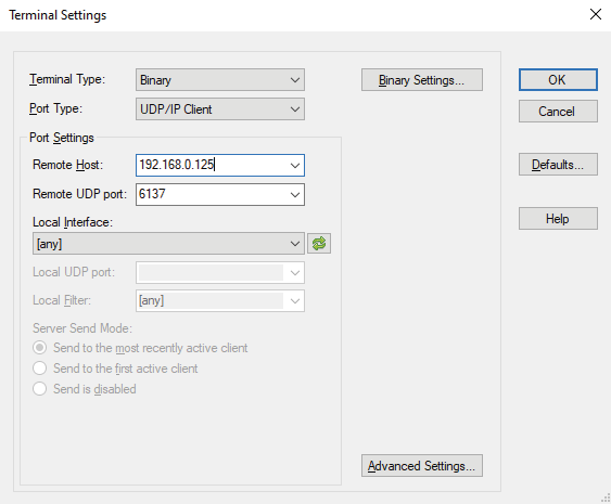
Terminal settings window of the YAT terminal application
Once the terminal window is opened, you can enter the UDP protocol commands, which are listed in the following sections:
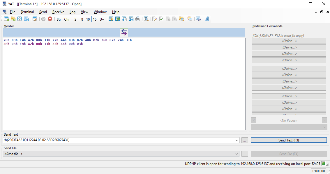
YAT terminal window
The format of a hexadecimal command in YAT is the following:
\h(<UDP_command>)
10.2. Setup
Before you begin configuration, please make sure of the following:
Step 1.Take note of the MAC address of your devices. You can find this information in the lower left corner of the top of the extenders.
Step 2.Connect your extenders to each other (point-to-point mode) or the switch (virtual hub in host-side extender).
Step 3.Connect your host-side extender to the host computer via a USB cable.
Step 4.Check that your host (or control) computer is in the same network as your extenders.
Step 5.Power on your devices.
Step 6.Pair the extenders with the Pairing to a Device message.
10.3. Protocol Description
The SwitchableUSB: Device Configuration Network Protocol described in this chapter works on top of User Datagram Protocol (UDP). The protocol is created to be able to discover and configure Icron modules on a local Ethernet network. The messages can be sent to the device as UDP packages via port no. 6137. In the following examples the packages are sent in Hexadecimal format.
Generic Packet Structure
|
Format |
Explanation |
|
Magic Number |
A value (0x2F03F4A2) that ensures that the following data is a configuration message. |
|
Message ID |
When the client sends a request, it chooses any value to insert in this field. The extender responding to the request will set this field in the reply to the same value. |
|
Protocol Version |
An integer from 0-255. All devices will support protocol 0 and one other protocol version. The Replying Device Information message will inform the client which version of the protocol it must speak in order to communicate with the extender. |
|
Command |
An integer from 0-255. This is the identifier of the command. The combination of the protocol version and the command identify a unique message type. |
▪All multi-byte fields are packed as big endian.
▪Messages are at least 10 bytes and at most 136 bytes in length.
▪Any string fields should be encoded using UTF-8.
Example
»2F03F4A2 00112244 00 00
10.3.1. Legend for the Commands
|
Format |
Description |
|
» |
Sent request |
|
« |
Received response |
INFO:Spaces seen in the examples are for enhancing readability, they can be left out of the commands.
10.4. Network Broadcast
10.4.1. Subnet Broadcast
To broadcast a packet to subnet you only have to use the broadcast IP of the subnet. For example to broadcast to a network configured as an IP range of 192.168.5.xxx, and a netmask of 255.255.255.0, the IP 192.168.5.255 is the broadcast IP address. In case of a network configured as an IP range of 10.xxx.xxx.xxx, and a netmask of 255.0.0.0, the IP 10.255.255.255 is the broadcast IP address.
Since routers drop broadcast IP packets with a destination outside of the network of the source, these broadcast packages must originate in the same network as the target devices.
10.4.2. All Local Subnet Broadcast
By broadcasting to the IP address 255.255.255.255 a broadcast packet can be sent out without knowing previously what the local network is. Microsoft Windows will, however, only send the packet out through the first configured network interface, so on a computer with multiple interfaces, each interface should send a separate broadcast network packet.
10.4.3. Mismatched Network Configuration
When broadcasting to a subnet using the network broadcast address (e.g. 192.168.5.255) and the extender is configured for a different network (e.g. IP=10.0.9.23 and netmask=255.0.0.0), the extender will not respond to the broadcast, as it will not recognize the IP address as a valid broadcast.
This should not happen when a proper DHCP server allocates addresses from the same pool for the network, however, it may happen when assigning static IP addresses or moving units between networks. In case of this occurence, the extender must be reset to a DHCP address in the way seen in the section Using DHCP. After this a static IP address can be assigned to the unit again.
10.5. Generic Replies
10.5.1. Acknowledge
This message is a generic ACK message that will be sent in response to all requests made by clients that do not require returning an additional data payload in the response. The Message ID field should be sufficient to determine which message is being acknowledged.
|
Byte Offset |
||
|
0 |
Magic Number |
|
|
2 |
||
|
4 |
Message ID |
|
|
6 |
||
|
8 |
Protocol Version = 0 |
Command = 3 |
Example
«2F03F4A2 00112244 00 03
10.5.2. Negative Acknowledge
This message is a generic NAK message that may be sent in response to a Pairing to a Device, Removing Device Pairing or Requesting Device Topology message. It indicates to the client that their request was received, but that no action will be taken as a result of that message. The Message ID field should be sufficient to determine which message this is a response to.
|
Byte Offset |
||
|
0 |
Magic Number |
|
|
2 |
||
|
4 |
Message ID |
|
|
6 |
||
|
8 |
Protocol Version = 3 |
Command = 8 |
Example
«2F03F4A2 00112244 03 08
10.6. Supported Messages
10.6.1. Requesting and Replying Device Information
Request
This message is sent from the client to an extender in order to evoke a Replying Device Information message. This message can be sent in a broadcast UDP message in order to discover all of the configurable USB extenders on the local network.
|
Byte Offset |
||
|
0 |
Magic Number |
|
|
2 |
||
|
4 |
Message ID |
|
|
6 |
||
|
8 |
Protocol Version = 0 |
Command = 0 |
Reply
This message is sent from an extender to a client in response to a Requesting Device Information message.
|
Byte Offset |
||
|
0 |
Magic Number |
|
|
2 |
||
|
4 |
Message ID |
|
|
6 |
||
|
8 |
Protocol Version = 0 |
Command = 1 |
|
10 |
MAC Address |
|
|
12 |
||
|
14 |
||
|
16 |
IP Address |
|
|
18 |
||
|
20 |
Network Aquisition Mode |
Supported Protocol Version |
|
22 |
Vendor |
|
|
52 |
||
|
54 |
Product |
|
|
84 |
||
|
86 |
Revision |
|
|
96 |
||
Field Descriptions
|
Field Data Type |
Explanation |
Values |
Value description |
|
MAC address |
The MAC address of the device |
||
|
IP address |
The current IP address of the device |
||
|
Network Acquisition Mode |
0 |
DHCP |
|
|
Supported Protocol Version |
This number specifies what protocol version the device supports beside protocol 0. |
||
|
Vendor |
A 32-byte, NUL-terminated string containing the vendor name of the device. |
||
|
Product |
A 32-byte, NUL-terminated string containing the product name of the device. |
||
|
Revision |
A 12-byte, NUL-terminated string containing the revision number of the device. |
Example
»2F03F4A2 00112244 00 00
«2F03F4A2 00112244 00 01 A8D236027431 C0A8007D 00 03
4C69676874776172652056697375616C20456E67696E656572696E6700000000
55534232302D314742452D485331300000000000000000000000000000000000 322E302E3600000000000000
10.6.2. Ping
This message is sent from a client to the device to check if a device is active. An Acknowledge message will be sent by the device in response.
Request
|
Byte Offset |
||
|
0 |
Magic Number |
|
|
2 |
||
|
4 |
Message ID |
|
|
6 |
||
|
8 |
Protocol Version = 0 |
Command = 2 |
Example
»2F03F4A2 00112244 00 02
«2F03F4A2 00112244 00 03
10.6.3. Requesting and Replying Extended Device Information
Request
Sent by a client to an extender in order to obtain additional information about the device that is not included in the Replying Device Information message from protocol 0.
|
Byte Offset |
||
|
0 |
Magic Number |
|
|
2 |
||
|
4 |
Message ID |
|
|
6 |
||
|
8 |
Protocol Version = 3 |
Command = 0 |
Reply
Sent by an extender to a client in response to a Requesting Extended Device Information message.
|
Byte Offset |
||
|
0 |
Magic Number |
|
|
2 |
||
|
4 |
Message ID |
|
|
6 |
||
|
8 |
Protocol Version = 3 |
Command = 1 |
|
10 |
LEX/REX |
Paired with MAC address |
|
12 |
||
|
14 |
||
|
16 |
||
Last six bytes can be repeated 0 or 1 times for an extender in point-to-point mode, or 0 to 7 times for a host side extender with virtual hub enabled.
Field Descriptions
|
Field Data Type |
Explanation |
Values |
Value description |
|
LEX/REX |
This determines whether the responding device is a host-side extender (LEX), or a device-side extender (REX). |
0 |
Host-side extender |
|
Paired with MAC address |
MAC address of an extender that this device is paired with. This field is optional and may be repeated up to 7 times. |
Example
»2F03F4A2 00112244 03 00
«2F03F4A2 00112244 03 01 00 A8D23602B357001B1302E3A4
This message is sent by a client to instruct an extender to try to pair with a different extender specified in the message. The client must send this message to both the host-side and device-side extenders, the contents adjusted respectively, but the order of the two messages does not matter. The extender will respond with an Acknowledge message if it is able to pair with a new device or a Negative Acknowledge message otherwise.These replies only mean that an attempt will be made to establish a link between the extenders, not that a link is already established. #pairing
In case of pairing several device-side extenders to a host-side extender, this step must be repeated for each pairing. #pairing
Field Descriptions
|
Field Data Type |
Explanation |
Values |
Value description |
|
Pairing to device MAC address |
The MAC address that the client is telling the extender to attempt to pair with. |
Request
|
Byte Offset |
||
|
0 |
Magic Number |
|
|
2 |
||
|
4 |
Message ID |
|
|
6 |
||
|
8 |
Protocol Version = 3 |
Command = 2 |
|
10 |
Pairing to Device MAC Address |
|
|
12 |
||
|
14 |
||
Example
»2F03F4A2 00112244 03 02 A8D236027431
«2F03F4A2 00112244 00 03
»2F03F4A2 00112244 03 02 A8D23602B357
«2F03F4A2 00112244 00 03
10.6.5. Removing Device Pairing
Sent by a client to an extender, instructing it to discard any existing pairing it has. This will effectively disconnect any USB devices that were downstream of the remote extender. The client must send this message to each of the extenders in the pairing. The extenders will respond with an Acknowledge message or with a Negative Acknowledge if it is already unpaired or paired to a different extender.
Field Descriptions
|
Field Data Type |
Explanation |
Values |
Value description |
|
Paired MAC address |
The MAC address that the client is telling the extender to disassociate from. |
Request
|
Byte Offset |
||
|
0 |
Magic Number |
|
|
2 |
||
|
4 |
Message ID |
|
|
6 |
||
|
8 |
Protocol Version = 3 |
Command = 3 |
|
10 |
Paired MAC Address |
|
|
12 |
||
|
14 |
||
Example
»2F03F4A2 00112244 03 03 A8D236027431
«2F03F4A2 00112244 00 03
»2F03F4A2 00112244 03 03 A8D23602B357
«2F03F4A2 00112244 00 03
10.6.6. Requesting and Replying Device Topology
Request
Sent by a client to a host-side extender in order to obtain the set of USB devices in the system. A device-side extender will respond with a Negative Acknowledge to this message.
|
Byte Offset |
||
|
0 |
Magic Number |
|
|
2 |
||
|
4 |
Message ID |
|
|
6 |
||
|
8 |
Protocol Version = 3 |
Command = 4 |
Reply
A host-side extender will send this message in response to a Requesting Device Topology message. The length of this message varies depending on the number of devices in the system. The combination of the information is enough for a client to build and display a device tree.
|
Byte Offset |
||
|
0 |
Magic Number |
|
|
2 |
||
|
4 |
Message ID |
|
|
6 |
||
|
8 |
Protocol Version = 3 |
Command = 5 |
|
10 |
USB Address |
USB Address Of Parent |
|
12 |
Port on Parent |
Is Device a Hub |
|
14 |
USB Vendor ID |
|
|
16 |
USB Product ID |
|
Bytes 10 to 16 can be repeated 0 to 32 times according to the number of USB devices.
INFO:Maximum number of USB devices is 32.
Field Descriptions
|
Field Data Type |
Explanation |
Values |
Value description |
|
USB Address |
An integer from 0 to 127. |
||
|
USB Address of Parent |
An integer from 1 to 127. If a USB Address is seen that is not listed as the USB Address of Parent for any of the devices, then that device is the root of the device topology. |
||
|
Port on Parent |
An integer from 1 to 127. 0 is not a valid number for a port on a hub, so this field will only be 0 if there is no USB device upstream before the host. |
||
|
Is Device a Hub |
0 |
False |
|
|
USB Vendor ID |
The USB Vendor ID from the device descriptor. |
||
|
USB Product ID |
The USB Product ID from the device descriptor. |
Example
»2F03F4A2 00112244 03 04
«2F03F4A2 00112244 03 05 2A27020004580186 2724010104B46506 24000001089D0001
Sent by a client to an extender to tell it to use DHCP to obtain an IP address. This message may be sent either as a UDP broadcast packet or a packet directed to a specific IP address known already. Regardless of whether the message was sent as a broadcast or not, the device will only switch to DHCP mode if the Target MAC Address field matches its own MAC address. When a valid Using DHCP message is received, the extender will send an Acknowledge message before discarding its static address configuration and aquiring an IP address via DHCP. If the Using DHCP message is sent to a device already in DHCP mode, it will still send an Acknowledge response, but no further actions are taken such as IP renewal. The client is able to tell the mode an extender is in by inspecting the Network Aquisition Mode field of the Replying Device Information message. #dhcp
Request
|
Byte Offset |
||
|
0 |
Magic Number |
|
|
2 |
||
|
4 |
Message ID |
|
|
6 |
||
|
8 |
Protocol Version = 3 |
Command = 6 |
|
10 |
Target MAC Address |
|
|
12 |
||
|
14 |
||
Field Descriptions
|
Field Data Type |
Explanation |
|
Target MAC address |
The MAC address of the device that will be set to use DHCP to obtain an IP address. |
Example
»2F03F4A2 00112244 03 06 A8D236027431
«2F03F4A2 00112244 00 03
10.6.8. Using Static IP
Sent by a client to an extender to tell it to use the static network configuration contained in this message. The IP, subnet mask and default gateway, as well as the network configuration are stored in permanent storage, so the device will keep the same network configuration after being power cycled. Similarly to the Using DHCP message, this message can be broadcast or sent to a specific device. Given that the Target MAC Address field matches the MAC address of the device, it will always respond with an Acknowledge message. Sending a Using Static IP message to a device already in a static configuration will enable the client to change the IP, subnet mask or default gateway of the device.
Request
|
Byte Offset |
||
|
0 |
Magic Number |
|
|
2 |
||
|
4 |
Message ID |
|
|
6 |
||
|
8 |
Protocol Version = 3 |
Command = 7 |
|
10 |
Target MAC Address |
|
|
12 |
||
|
14 |
||
|
16 |
IPv4 Address |
|
|
18 |
||
|
20 |
Subnet Mask |
|
|
22 |
||
|
24 |
Default Gateway |
|
|
26 |
||
Field Descriptions
|
Field Data Type |
Explanation |
|
Target MAC Address |
The MAC address of the device that will be set to use static network configuration. |
|
IPv4 Address |
The IPv4 address being assigned to this device encoded as a 32-bit integer. |
|
Subnet Mask |
The subnet mask of the network the device is on. |
|
Default Gateway |
Sets the default gateway of the device. |
Example
»2F03F4A2 00112244 03 07 001B1302E3A4 C0A8007E FFFFFF00 C0A80001
«2F03F4A2 00112244 00 03
10.6.9. Using Filtering Strategy
Sent by a client to an extender to set it to use a certain type of filtering strategy contained in the message. The filtering strategy denotes the type of devices to be filtered out by the extenders. An Acknowledge message will be sent back to the client if the extender supports device class filtering and a valid strategy was selected. Otherwise, a Negative Acknowledge will be sent to the client.
Field Descriptions
|
Field Data Type |
Values |
Value description |
|
Filtering Strategy |
0 |
Allow all devices |
Request
|
Byte Offset |
||
|
0 |
Magic Number |
|
|
2 |
||
|
4 |
Message ID |
|
|
6 |
||
|
8 |
Protocol Version = 3 |
Command = 9 |
|
10 |
Filtering Strategy |
|
Example
»2F03F4A2 00112244 03 09 02
«2F03F4A2 00112244 00 03
10.6.10. Reseting Device
This message is sent from the client to the extender. Upon receiving this message, the device resets.
Request
|
Byte Offset |
||
|
0 |
Magic Number |
|
|
2 |
||
|
4 |
Message ID |
|
|
6 |
||
|
8 |
Protocol Version = 3 |
Command = 12 |
Example
»2F03F4A2 00112244 03 0C
«2F03F4A2 00112244 00 03
10.6.11. Requesting and Replying Configuration Response Data
Request
This message is sent from the client to an extender in order to evoke a Replying Configuration Response Data message.
|
Byte Offset |
||
|
0 |
Magic Number |
|
|
2 |
||
|
4 |
Message ID |
|
|
6 |
||
|
8 |
Protocol Version = 3 |
Command = 13 |
Reply
This message is sent from an extender to a client in response to a Requesting Configuration Response Data message.
|
Byte Offset |
||
|
0 |
Magic Number |
|
|
2 |
||
|
4 |
Message ID |
|
|
6 |
||
|
8 |
Protocol Version = 3 |
Command = 14 |
|
10 |
High Speed Status |
MSA Status |
|
12 |
Vhub Status |
Current Filter Status |
|
14 |
IP Acquisition Mode |
Reserved |
|
16 |
MAC Address |
|
|
18 |
||
|
20 |
||
|
22 |
Reserved |
|
|
24 |
Paired with MAC Address |
|
|
64 |
||
|
66 |
Port Number |
|
|
68 |
IP Address |
|
|
70 |
||
|
72 |
Subnet Mask |
|
|
74 |
||
|
76 |
Default Gateway |
|
|
78 |
||
|
80 |
DHCP Server |
|
|
82 |
||
|
84 |
Number of Vhub Ports |
Reserved |
|
86 |
VID |
|
|
88 |
PID |
|
|
90 |
Brand ID |
|
|
92 |
Vendor |
|
|
120 |
||
|
122 |
Product |
|
|
152 |
||
|
154 |
Revision |
|
|
166 |
||
Field Descriptions
|
Field Data Type |
Explanation |
Values |
Value description |
|
High Speed |
0 |
Disabled |
|
|
MSA |
0 |
Disabled |
|
|
Vhub |
0 |
Disabled |
|
|
Current Filter Status |
0 |
Allow all devices |
|
|
IP Acquision Mode |
0 |
DHCP |
|
|
Reserved |
This field is reserved and is set to 0. |
||
|
MAC Address |
The MAC address of the device. |
||
|
Paired with MAC Address |
MAC address of an extender that this device is paired with. This field is optional and may be repeated up to 7 times. |
||
|
Port Number |
The port number that this device is connected to. |
||
|
IP Address |
The current IP address of the device. |
||
|
Subnet Mask |
The subnet mask of the device. |
||
|
Default Gateway |
The default gateway for the device. |
||
|
DHCP Server |
The DHCP server of the device. |
||
|
Num of Vhub ports |
The number of downstream ports of the device. |
||
|
VID |
The Vendor ID of the device. |
||
|
PID |
The Product ID of the device. |
||
|
Brand ID |
The Brand ID of the device. |
0 |
Non-vendor locked device |
|
Vendor |
A 32-byte NUL-terminated string containing the vendor name of the device. |
||
|
Product |
A 32-byte NUL-terminated string containing the product name of the device. |
||
|
Revision |
A 12-byte NUL-terminated string containing the revision number of the device. |
Example
»2F03F4A2 00112244 03 0D
«2F03F4A2 00112244 03 0E 01 00 01 00 00 00 A8D23602B357 00 00
A8D236027431000000000000000000000000000000000000000000000000000000000000000000000000 17F9 C0A8007F FFFFFF00 C0A80001 C0A80001 07 00 6F27 6E01 0000
4C69676874776172652056697375616C20456E67696E656572696E6700000000
55534232302D314742452D445334000000000000000000000000000000000000 322E302E3600000055534220
10.6.12. Requesting and Replying Link Status
Request
This message is sent from the client to an extender in order to obtain the link status of the paired units.
|
Byte Offset |
||
|
0 |
Magic Number |
|
|
2 |
||
|
4 |
Message ID |
|
|
6 |
||
|
8 |
Protocol Version = 3 |
Command = 15 |
Reply
This message is sent from the extender to the client in response to a Requesting Link Status Information message. The message will contain information for all 7 devices that could be paired. If the number of paired devices is less than 7, the unpaired fields are set to 0. Thus, the size of the structure sent remains the same regardless of the number of paired units.
|
Byte Offset |
||
|
0 |
Magic Number |
|
|
2 |
||
|
4 |
Message ID |
|
|
6 |
||
|
8 |
Protocol Version = 3 |
Command = 16 |
|
10 |
Link Status of Device 1 |
Link Status of Device 2 |
|
12 |
Link Status of Device 3 |
Link Status of Device 4 |
|
14 |
Link Status of Device 5 |
Link Status of Device 6 |
|
16 |
Link Status of Device 7 |
Reserved |
|
18 |
MAC Address of Device 1 |
|
|
20 |
||
|
22 |
||
|
24 |
MAC Address of Device 2 |
|
|
26 |
||
|
28 |
||
|
30 |
MAC Address of Device 3 |
|
|
32 |
||
|
34 |
||
|
36 |
MAC Address of Device 4 |
|
|
38 |
||
|
40 |
||
|
42 |
MAC Address of Device 5 |
|
|
44 |
||
|
46 |
||
|
48 |
MAC Address of Device 6 |
|
|
50 |
||
|
52 |
||
|
54 |
MAC Address of Device 7 |
|
|
56 |
||
|
58 |
||
Field Descriptions
|
Field Data Type |
Explanation |
Values |
Value description |
|
Link Status |
0 |
Device not paired |
|
|
Reserved |
This field is reserved and is set to 0. |
||
|
Paired with MAC Address |
Each MAC address uses 6 bytes and the field value will be set to 0 if there is no device paired. |
Example
»2F03F4A2 00112244 03 0F
«2F03F4A2 00112244 03 10 02 01 00 00 00 00 00 00 A8D23602B357001B1302E3A4000000000000000000000000000000000000000000000000000000000000
10.6.13. Removing All Pairings
This command is sent by the client to an extender to instruct it to clear all of its pairings. This message may be sent to an extender that has no current pairings, but it will have no effect.
Request
|
Byte Offset |
||
|
0 |
Magic Number |
|
|
2 |
||
|
4 |
Message ID |
|
|
6 |
||
|
8 |
Protocol Version = 3 |
Command = 17 |
Example
»2F03F4A2 00112244 03 11
«2F03F4A2 00112244 00 03
10.6.14. Force Pairing to Device
This command is sent by the client to an extender to instruct it to clear all of its existing pairings and then try to pair with a different extender specified in the message. The client must send this message to both a host-side extender and a device-side extender to instruct them to be paired together, but the order of the two messages does not matter. The extender will respond with an Acknowledge message if it is able to pair with a new device or a Negative Acknowledge otherwise. #pairing
INFO:The Acknowledge message only indicates an attempt will be made to establish a link between the extenders, not that a link is already established. #pairing
Field Descriptions
|
Field Data Type |
Explanation |
|
Force Pair to Device MAC Address |
The MAC address that the client is telling the extender to attempt to pair with. |
Request
|
Byte Offset |
||
|
0 |
Magic Number |
|
|
2 |
||
|
4 |
Message ID |
|
|
6 |
||
|
8 |
Protocol Version = 3 |
Command = 18 |
|
10 |
Force Pair to Device MAC Address |
|
|
12 |
||
|
14 |
||
Example
»2F03F4A2 00112244 03 12 A8D23602B357
«2F03F4A2 00112244 00 03
»2F03F4A2 00112244 03 12 A8D236027431
«2F03F4A2 00112244 00 03
10.6.15. Reseting Force Pairing to Device
This command is the same as the Force Pairing to Device command, but it resets the system after the pairing with the other extender happens.
INFO:This command only works when sent to a host-side extender. When sent to a device-side extender, it will reset the device, but pairing will not happen.
Field Descriptions
|
Field Data Type |
Explanation |
|
Force Pair to Device MAC Address |
The MAC address that the client is telling the extender to attempt to pair with. |
Request
|
Byte Offset |
||
|
0 |
Magic Number |
|
|
2 |
||
|
4 |
Message ID |
|
|
6 |
||
|
8 |
Protocol Version = 3 |
Command = 19 |
|
10 |
Force Pair to Device MAC Address |
|
|
12 |
||
|
14 |
||
Example
»2F03F4A2 00112244 03 13 A8D23602B357
«2F03F4A2 00112244 00 03
10.6.16. Writing the Extended Configuration Variable
This command writes the extended configuration variable. It is used to control the following configuration parameters:
▪Simultaneous Users Interaction (SUI) and Mass Storage Acceleration (MSA)
▪Enabling/Disabling DHCP option
▪DCF configuration
The client will set the bit of configuration mask corresponding to which configuration variable they want to change and set the configuration variable as defined below in the field descriptions. The system will reset after a variable is set.
ATTENTION!Please be aware that while this command is packed as big endian, depending on the terminal application and the Operation System, it may be reversed by the application to display as little endian.
Field Descriptions
|
Field Data Type |
Explanation |
Values |
Value description |
|
Configuration Mask |
This is a 16-bit mask, in which only the first 4 are used. The remaining are reserved and set to 0. |
Bit 0 |
Change only SUI and MSA fields in the configuration variable. |
|
Configuration Variable |
This is the 32 bits defined as it follows: |
||
|
Simultaneous Users Interaction (SUI) and Mass Storage Acceleration (MSA) (2-bit field starting at bit 0) |
0 |
SUI off, MSA off |
|
|
Enabling/Disabling the DHCP option 60 (1-bit field, at bit 2) |
|||
|
Reserved, set to 0 (1-bit field, at bit 3) |
|||
|
Disabling DCF or Set DCF options - DCF configuration field (4-bit field, starting at bit 4) |
0 |
Allow all devices (DCF disabled) |
Request
|
Byte Offset |
||
|
0 |
Magic Number |
|
|
2 |
||
|
4 |
Message ID |
|
|
6 |
||
|
8 |
Protocol Version = 3 |
Command = 50 |
|
10 |
Configuration Mask |
|
|
12 |
Extended Configuration Variable |
|
|
14 |
||
Example
»2F03F4A2 00112244 03 32 0100 01000000
«2F03F4A2 00112244 00 03
INFO:Please take note that depending on the SUI setting, the extender may take up several USB tiers. If SUI is turned off, the extender takes up one USB tier. If SUI is turned on, it takes up two USB tiers. For optimal operation please make sure you do not exceed the maximum tier level (generally 7).
10.6.17. Requesting the Extended Configuration Variable
Request
This command is sent from the client to the extender to request the extended configuration variable.
|
Byte Offset |
||
|
0 |
Magic Number |
|
|
2 |
||
|
4 |
Message ID |
|
|
6 |
||
|
8 |
Protocol Version = 3 |
Command = 51 |
Reply
This command is a response to the Requesting Extended Configuration Variable command, sent from the extender to the client. It offers the extended configuration variable.
|
Byte Offset |
||
|
0 |
Magic Number |
|
|
2 |
||
|
4 |
Message ID |
|
|
6 |
||
|
8 |
Protocol Version = 3 |
Command = 52 |
|
10 |
Extended Configuration Variable |
|
|
12 |
||
Field Descriptions
|
Field Data Type |
Explanation |
Values |
Value description |
|
Configuration Variable |
This is the 32 bits defined as it follows: |
||
|
Simultaneous Users Interaction (SUI) and Mass Storage Acceleration (MSA) (2-bit field starting at bit 0) |
0 |
SUI off, MSA off |
|
|
Enabling/Disabling the DHCP option 60 (1-bit field, at bit 2) |
|||
|
Reserved, set to 0 (1-bit field, at bit 3) |
|||
|
Disabling DCF or Set DCF options - DCF configuration field (4-bit field, starting at bit 4) |
0 |
Allow all devices (DCF disabled) |
Example
»2F03F4A2 00112244 03 33
«2F03F4A2 00112244 03 34 00000001
The Matrix Management Unit (MMU) can be updated by using Lightware Device Updater v2 (LDU2) software via Ethernet. The firmware pack with the necessary components (*.lfp2 file) for your specific product, and the LDU2 application can be downloaded from the Support page of our website www.lightware.com.
ATTENTION!After updating a main version of the UBEX MMU or endpoint firmware package (e.g. 2.x.x to v3.x.x), downgrading is highly not recommended. It may causes losing of settings and incompability issues with earlier backups.
ATTENTION!The firmware update process has an effect on the configuration and the settings of the device. For more details, please see the Keeping the Configuration Settings section before the update.
DIFFERENCE:Lightware highly recommends using the same and cohesive firmware versions on the UBEX extenders and the MMU. Connection between extenders installed with different versions might cause unexpected performance failures. See the list of cohesive endpoint and MMU firmware versions in the Endpoint Firmware Packages in the MMU section.
11.1. Preparation
Most Lightware devices can be controlled over several interfaces (e.g. Ethernet, USB, RS-232). But the firmware can usually be updated over one dedicated interface, which is the Ethernet in most cases.
If you want to update the firmware of one or more devices you need the following:
▪LFP2 file,
▪LDU2 software installed on your PC or Mac.
Both can be downloaded from www.lightware.com.
Optionally, you can download the release notes file in HTML format.
11.1.1. About the Firmware Package (LFP2 File)
All the necessary tools and binary files are packed into the LFP2 package file. You need only this file to do the update on your device.
▪This allows the use of the same LFP2 package for different devices.
▪The package contains all the necessary components, binary, and other files.
▪The release notes is included in the LFP2 file, which is displayed in the window where you select the firmware package file in LDU2.
11.1.2. LDU2 Installation
ATTENTION!Minimum system requirement: 2 GB RAM. The minimum screen resolution is 1600x900.
ATTENTION!Certain ports are used for the communication in the background; please check the list in the Applied Ports (Network Settings) section.
INFO:The Windows, Mac and Linux application has the same look and functionality.
Download the software from www.lightware.com.
Installation in case of Windows OS
Run the installer. If the User Account Control displays a pop-up message, click Yes.
Installation Modes
|
Normal install |
Snapshot install |
|
Available for Windows, macOS and Linux |
Available for Windows only |
|
The installer can update only this instance |
Cannot be updated |
|
One updateable instance may exist for all users |
Many different versions can be installed for all users |
ATTENTION!Using the default Normal install is highly recommended.
INFO:If you have a previously installed version, you will be prompted to remove the old version before installing the new one.
Installation in case of macOS
Mount the DMG file by double clicking on it, and drag the LDU2 icon over the Applications icon to copy the program into the Applications folder. If you want to copy LDU2 into another location, just drag the icon over the desired folder.
ATTENTION!Please check the firewall settings on the macOS device. LDC needs to be added to the exceptions of the blocked software for the proper operation.
INFO:This type of installer is equal to the Normal install of Windows.
Installation in case of Linux

Step 1.Download the archive file (tar.gz) from www.lightware.com and unpack it to a temp folder.
Step 2.Run the install_ldu2.sh file in the temp folder. The script will install LDU2 into the following folder: HOME/.local/share/lightware/ldu2.
Step 3.The folder above will contain this file: LightwareDeviceUpdaterV2.sh that can be used to start LDU2.
11.2. Running the Software
ATTENTION!The computer that runs LDU2 and the target device (that will be updated) must be in the same subnet. The update cannot be performed behind a firewall or gateway.
You have two options:
▪Starting the LDU2 by double-clicking on the shortcut/program file, or
▪Double-clicking on an LFP2 file.
11.2.1. LDU2 Interfaces
The software can be used over:
▪The Graphical User Interface (GUI), or by
▪The Command Line Interface (CLI).
LDU2 Auto-Update
At startup, the software checks if a newer version is available on the web.
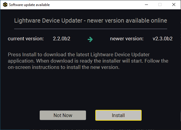
Main Screen

When the software is started by the shortcut, the device discovery screen appears. Press the Discover Devices button to start finding the Lightware devices:
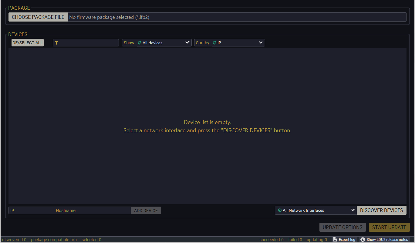
LDU2 welcome screen
If you start the software by double-clicking on the LFP2 file, the firmware will be loaded. Press the Discover devices button; all the devices will be listed that are compatible with the selected firmware pack.
INFO:If you press the Choose package file button, the release notes of the LFP2 file will be displayed in the right panel.
Device List
When the discovery has completed, the devices available on the network are listed in the application.
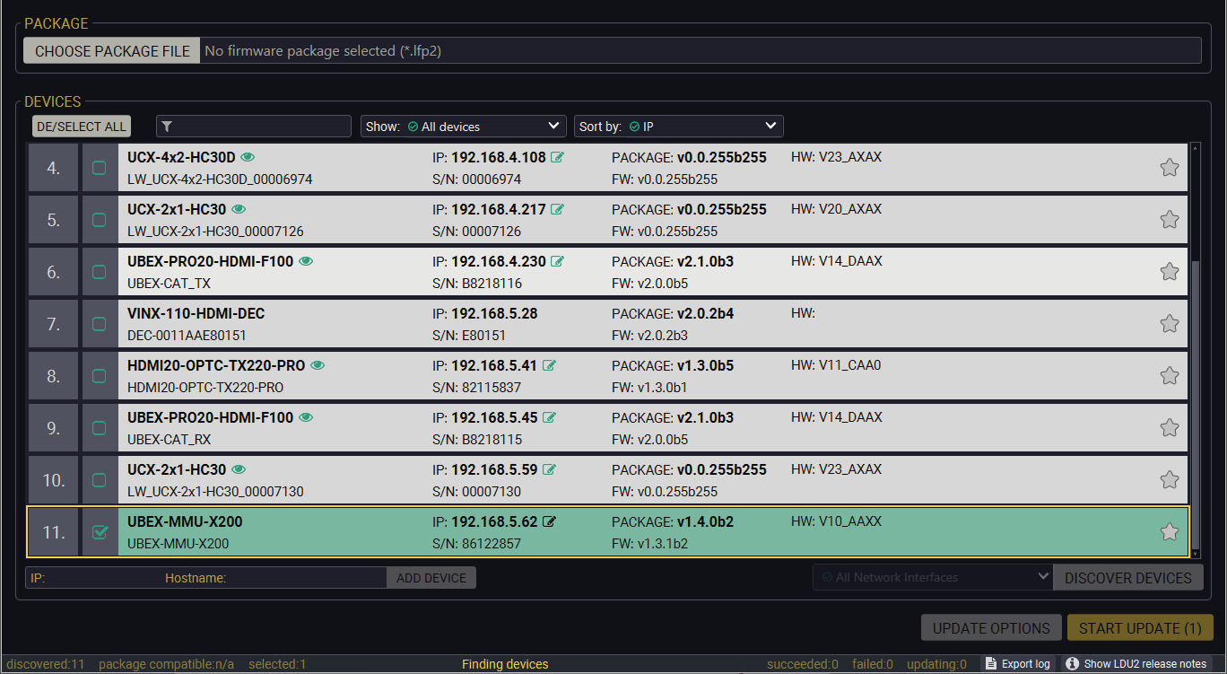
If the desired device is not discovered, you can add it by typing the IP address or the host name in the dedicated field and pressing the Add device button.
ATTENTION!If the device cannot be added by the hostname, please use the IP address.
Legend of the Icons
|
|
IP address editor |
The IP address of the device can be changed in the pop-up window. |
|
|
Identify me |
Clicking on the icon results in the front panel LEDs blinking for 10 seconds, which helps to identify the device phisically. |
|
|
Favorite device |
The device has been marked, thus the IP address is stored. When a device is connected with that IP address, the star will be highlighted in that line. |
|
|
Further information available |
Device is unreachable. Change the IP address by pressing the IP address editor icon or use the front panel buttons (if available). |
|
|
Cleartext login enabled |
The password-protection is enabled. You have to enter the password to perform the firmware update in the Parameters window or in the appearing window in the beginning of the update. |

|
Service mode |
The device is in bootload mode. Backup and restore cannot be performed in this case. |
ATTENTION!While the firmware is being updated, the normal operation mode is suspended, as the device is switched to bootload mode. Signal processing is not performed. Do not interrupt the firmware update. If any problem occurs, reboot the unit and restart the process.
Keeping the Configuration Settings
By default, device configuration settings are restored when firmware update is finished. If factory reset has been chosen in the parameters window, all device settings will be erased. In the case of factory reset, you can save the settings of the device in the Lightware Device Controller software and restore it later.
The following flow steps demonstrate how this function works in the background.
Step 1.Create a backup
The current configuration of the device is being saved into a configuration backup file on your computer.
Step 2.Start the Update
The device reboots and starts in bootload mode (firmware update mode).
Step 3.Upgrade
The CPU firmware is changed to the new one.
Step 4.Factory reset
All configuration settings are restored to the factory default values.
Step 5.Conversion / Restore
The firmware package checks the backup data before the restoration procedure, and if it is necessary, a conversion is applied to avoid incompatibility problems between the firmware versions. All configuration settings are restored to the device after the conversion.
If the factory default option is selected in the Parameters window, the conversion / restore procedure will not be performed!
Step 6.Finish
Once the firmware update procedure is finished, the device reboots and is ready to use.
The following instructions belong to the UBEX-MMU-X200 Matrix Management Unit only. For the updating of the endpoint devices see the Endpoint Update - Centralized Firmware Update / Endpoint Update - Manual Method section.
11.4.1. Establish Connection
Make sure that the computer and the device are connected over Ethernet and the connection is established between them.
11.4.2. Start the LDU2 Application and Follow the Steps
The Steps of the Update in Quick Summary:
Step 1.Select the firmware package file.
Step 2.Select the unit for updating.
Step 3.Check the update parameters.
Step 4.Start the update and wait until it is finished.
Step 5.Wait until the unit reboots with the new firmware.
Update Steps
Step 1.Select the firmware package.
Click on the Choose Firmware Package button and navigate to the location where the LFP2 file of the MMU is saved. When you click on the name of package, the preview of the release notes is displayed on the right side.
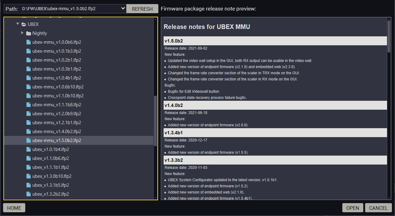
Firmware file browser and the release notes window
After the package file is loaded, the list is filtered to show compatible devices only. The current firmware version of the device is highlighted in orange if it is different from the version of the package loaded.
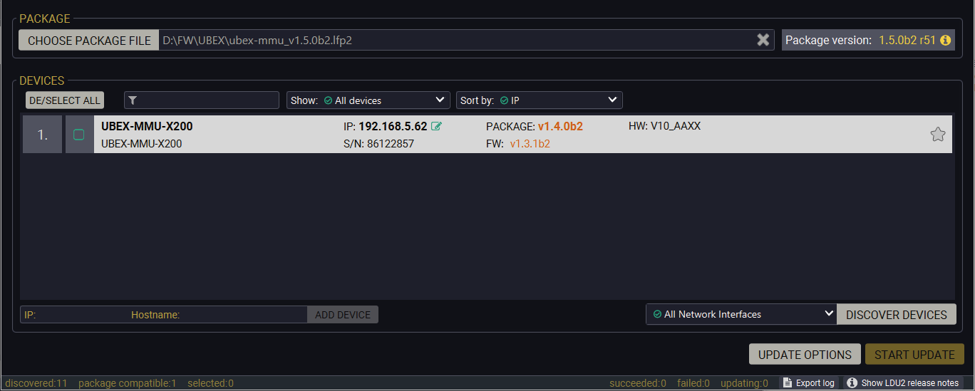
Filtered device list based on the selected firmware package
Step 2.Select the unit for updating.
Pick the MMU(s) for updating. The selected line will be highlighted in green.
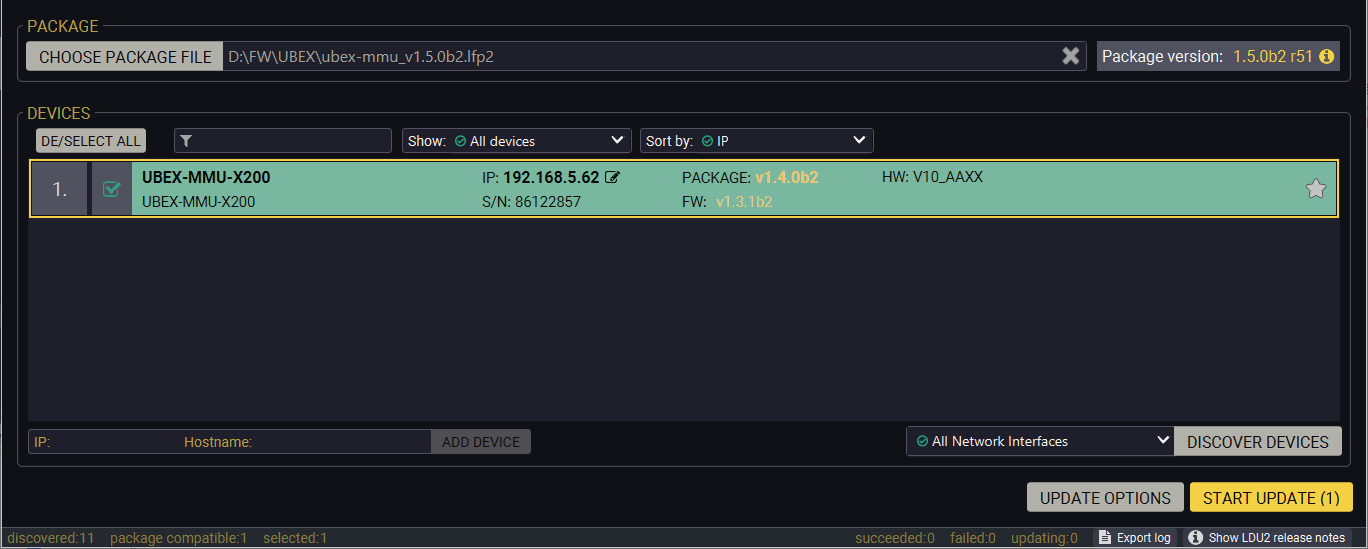
The unit is selected for updating
Step 3.Check the update options.
ATTENTION!The default settings in the Parameters window should be fine for most cases. Please do not modify them if it is not necessary.
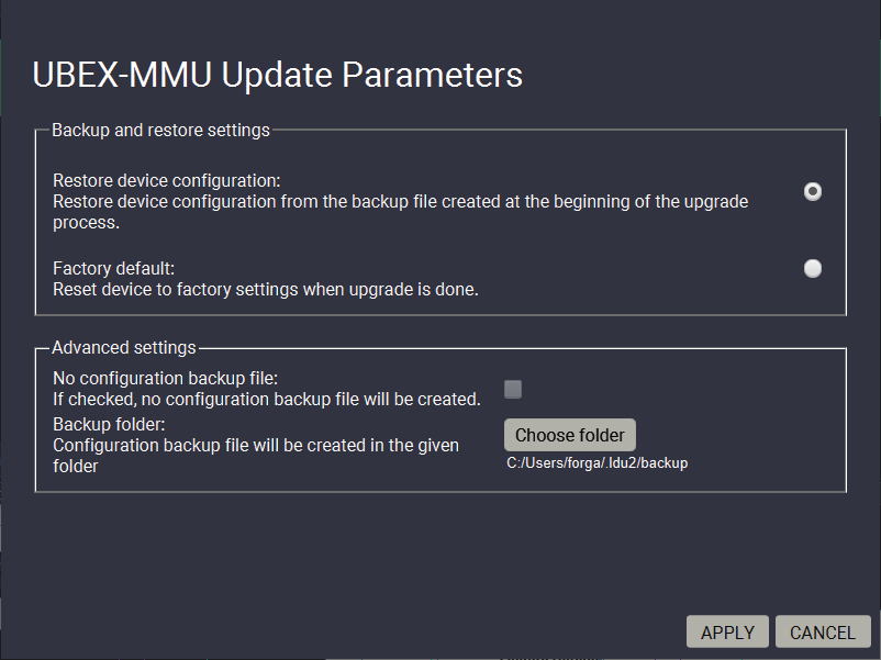
Click on the Update Options button to configure the firmware update.
Backup Folder
Set the path of the device configuration backup file which is created automatically. The default path is USER_HOME/.ldu2/backup.
Restore Device Configuration
When it is enabled, the configuration settings of the MMU will be restored after the update. Enabled by default.
Factory Default
If it is checked, all user settings and parameters will be cleared and the factory default settings will be applied to the device when the update is done. See the whole list of factory default settings of the MMU in the UBEX-MMU-X200 section.
Once the parameters are set, click on the Apply button to save the settings.
Step 4.Start the update and wait until it is finished.
ATTENTION!After updating the MMU cannot be downgraded to versions prior to v1.2.0.
Click on the Start Update button to start the procedure. The status is shown in percent in the right side of the device line and the status of all of the procedures is shown in the lower light green progress bar.
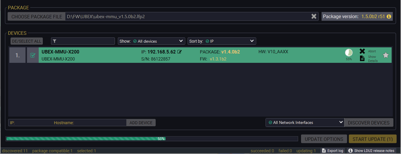
Firmware update is in progress
ATTENTION!While the firmware is being updated, the normal operation mode is suspended as the MMU is switched to bootload mode. Do not interrupt the firmware update. If any problem occurs, reboot the device and restart the process.
INFO:The device might reboot several times during the firmware update procedure.
INFO:The percent counter can be changed to "Waiting for device" description in few times during the update. In this case the MMU performs internal procedures and it is the part of the normal operation.
Step 5.Wait until the unit reboots with the new firmware.
Once the firmware update procedure is completed, the unit reboots with the new firmware.
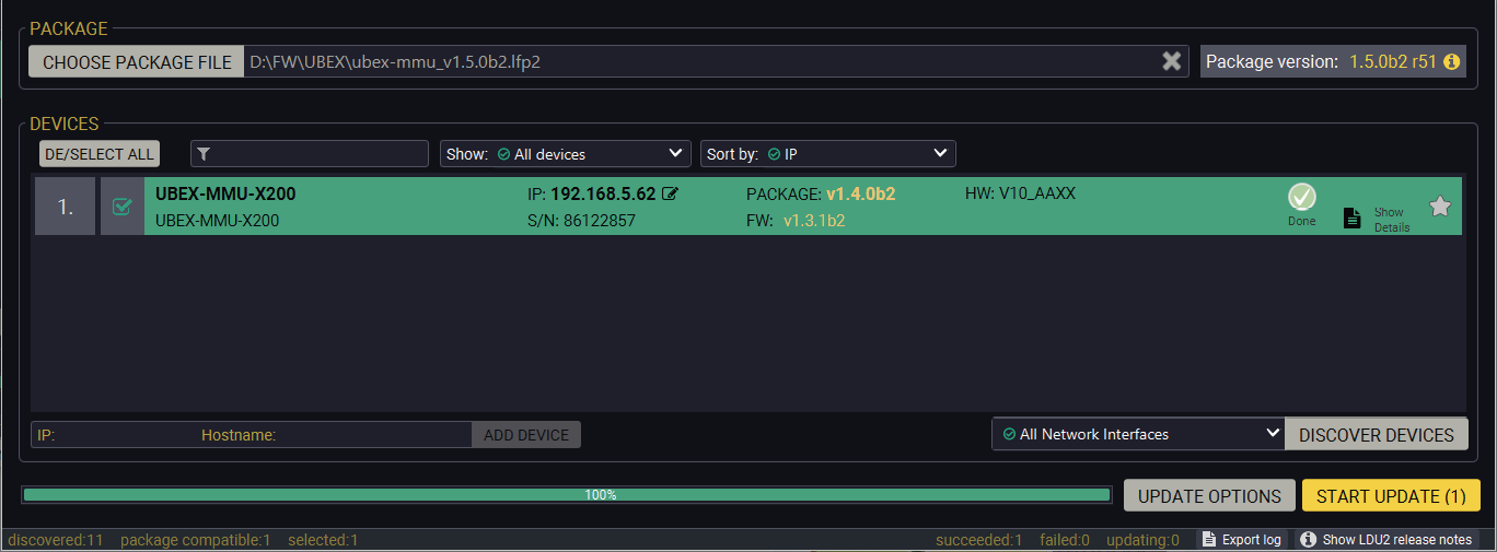
Firmware update procedure is done
11.5. Endpoint Update - Centralized Firmware Update
The following instructions belong to the endpoint devices (UBEX-PRO20-HDMI-F100 / F110 / F111 / F120 / F121 / F130 / R100 series) only. For the updating of the MMU see the Updating via GUI - MMU section.
ATTENTION!The centralized firmware update feature is working from the installed MMU firmware v1.1.0 and endpoint firmware v1.3.1 and available for the later firmware package versions. The endpoint firmware packages till v1.3.1 can be installed with LDU2 software - see the details in the Endpoint Update - Manual Method section.
ATTENTION!Lightware highly recommends using the same and cohesive firmware versions on the UBEX extenders and the MMU. Connection between extenders installed with different versions might cause unexpected performance failures. See the list of cohesive endpoint and MMU firmware versions in the Endpoint Firmware Packages in the MMU section.
11.5.1. Description
The centralized firmware update method for the connected endpoint devices is the most comfortable way to keep your devices up to date. The selected units can be updated together, the procedure is supervised by the MMU, no user interaction is needed. During the firmware update, the AV transmission continues smoothly in the unselected endpoint devices.
11.5.2. Technical Background
The centralized firmware update for the endpoint devices is launched and controlled by the user and supervised by the MMU. The firmware package of the endpoint devices is built in the firmware package of the MMU which is installed when the MMU is updated. It follows that the firmware package versions of the endpoints and the MMU are linked - see the list of the coupled firmware package versions in the Endpoint Firmware Packages in the MMU section. No LDU2 software and MMU firmware package is necessary for the centralized firmware update method. The greatest advantage of the linked firmware packages is that they are developed and tested together for the best user experience.
When the firmware update is launched, the selected endpoint devices are set to bootload (firmware update) mode. The MMU sends the firmware package to the endpoints in multicast messages and repeats it until all selected endpoints confirm the new firmware version.
INFO:The centralized firmware update method requires the same network switch configuration requirements as the AV signal transmission. See the details in the Ethernet Switch Configuration section.
The update procedure can be launched by two ways as following:
▪via Lightware Device Controller (LDC) software - see the detailed instructions in the Centralized Firmware Update - Detailed Instructions section (on the next page);
▪via LW3 protocol commands - see the detailed instructions in the Centralized Firmware Update section.
What If the MMU is Down during the Firmware Update?
The MMU and the updated endpoint devices communicate with each other in the entire time of the firmware update. The MMU checks the status of all updating endpoints and streams the endpoint firmware package on the network until all endpoints responds the completed status and to be claimed successfully. If the connection is lost by the MMU with the endpoints for some reason, the update procedure will be restarted automatically on the endpoints which has not sent 'completed' status when the MMU is live on the network again.
What If the Firmware Update is Failed on an Endpoint Device?
The endpoint device cannot be harmed in the case of firmware update failure. The procedure can be repeated/restarted anytime when it is necessary.
11.5.3. Centralized Firmware Update - Detailed Instructions
Preparing the Update
Step 1.Open the Lightware Device Controller (LDC) software.
Step 2.Establish connection with the MMU.
Step 3.Navigate to the Settings / System Monitor / Update Firmware menu.
The Layout of the Update Firmware Menu
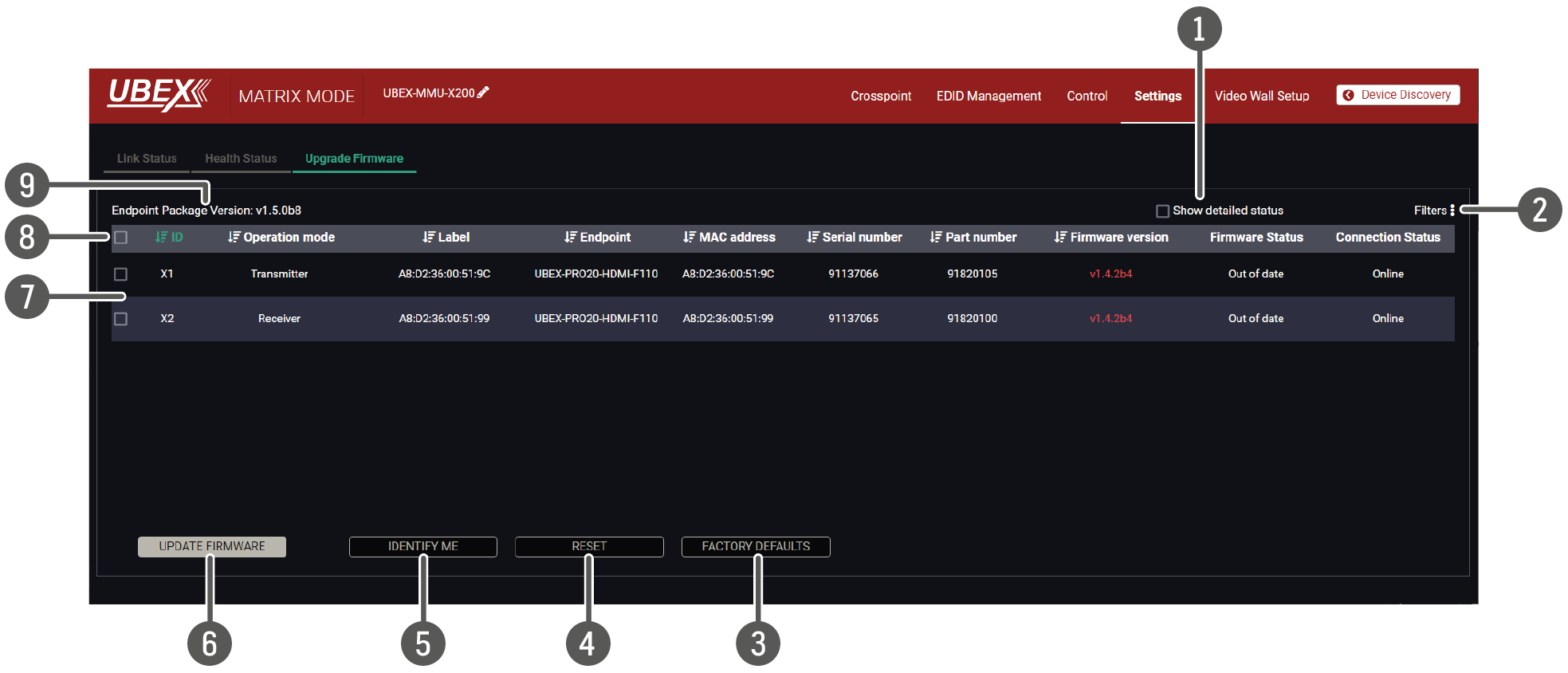
|
1 |
Show detailed status switcher |
The explanation of the two available options is the following: ▪Enabled: the last text message of the firmware update status is displayed in the Firmware Status column. ▪Disabled: the recent status of the firmware update is displayed in percent. |
|
2 |
Filters |
The list of the endpoint devices can be filtered, see the details in the Filters section (on the right side). |
|
3 |
Factory defaults button |
Clicking on the button results applying factory default settings on the selected endpoint devices. See the details about the applied settings in the Factory Default Settings section. |
|
4 |
Reset button |
Clicking on the button results restarting the selected endpoint devices. |
|
5 |
Identify me button |
Clicking on the button causes the four front panel LEDs blink in green for 10 seconds. The feature helps to identify the device itself in the rack shelf. |
|
6 |
Update firmware button |
Clicking on the button results starting the firmware update procedure on the selected endpoint devices with the package version displayed in the Endpoint Package Version. |
|
7 |
Endpoint device selectors |
Clicking on the squares the endpoint devices will be selected for firmware update, identify me function, reseting or factory defaults setting. Clicking on square next to the header results selecting all devices in the list. |
|
8 |
Header |
The header of the endpoint list. Clicking on the icon sorts the list based on the category of the column (e.g. ID, operation mode, label, etc). |
|
9 |
Endpoint firmware package version |
The firmware package version of the endpoint is displayed here which is built in the MMU. This version will be applied on the endpoint devices after the centralized firmware update is completed. |
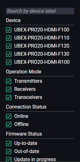
Applying filters help to find the required endpoint devices for updating in case of a larger UBEX matrix. The function contains the following filter categories:
▪Device:
=UBEX-PRO20-HDMI-F100
=UBEX-PRO20-HDMI-F110
=UBEX-PRO20-HDMI-F111
=UBEX-PRO20-HDMI-F120
=UBEX-PRO20-HDMI-F121
=UBEX-PRO20-HDMI-F130
=UBEX-PRO20-HDMI-R100
▪Operation Mode:
=Transmitters
=Receivers
=Transceivers
▪Connection Status:
=Online
=Offline
▪Firmware Status:
=Up-to-date
=Out of date
=Update in progress
Update Steps
Step 1.Select the units for updating.
Pick the endpoint devices for updating by clicking on the endpoint device selector squares on the left side. Clicking on square next to the header results selecting all devices in the list. The selected line will be highlighted in green.
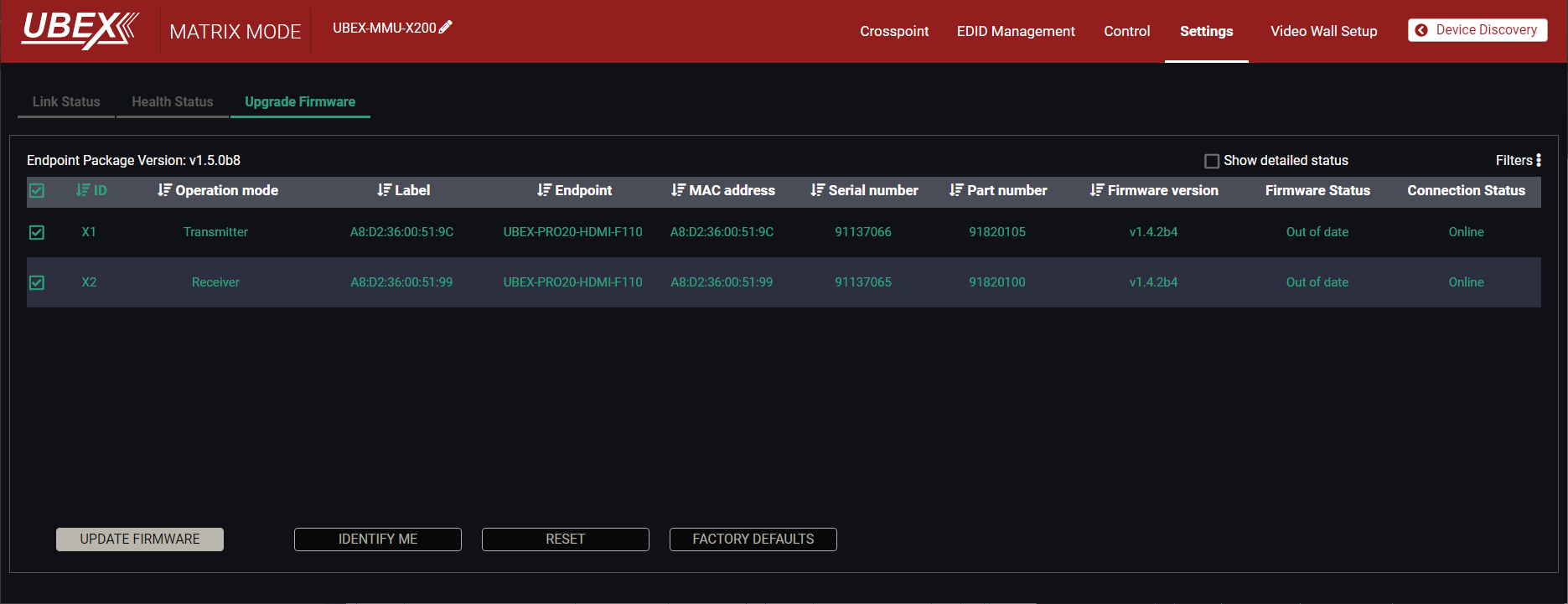
The units are selected for updating
Step 2.Start the update and wait until it is finished.
Click on the Update Firmware button to start the procedure. At first a warning message pops up.
ATTENTION!The update is not backward compatible with the version running on some endpoints. After updating these endpoints cannot be downgraded to versions prior to v1.4.0.
Select Yes if you want to continue the update procedure.
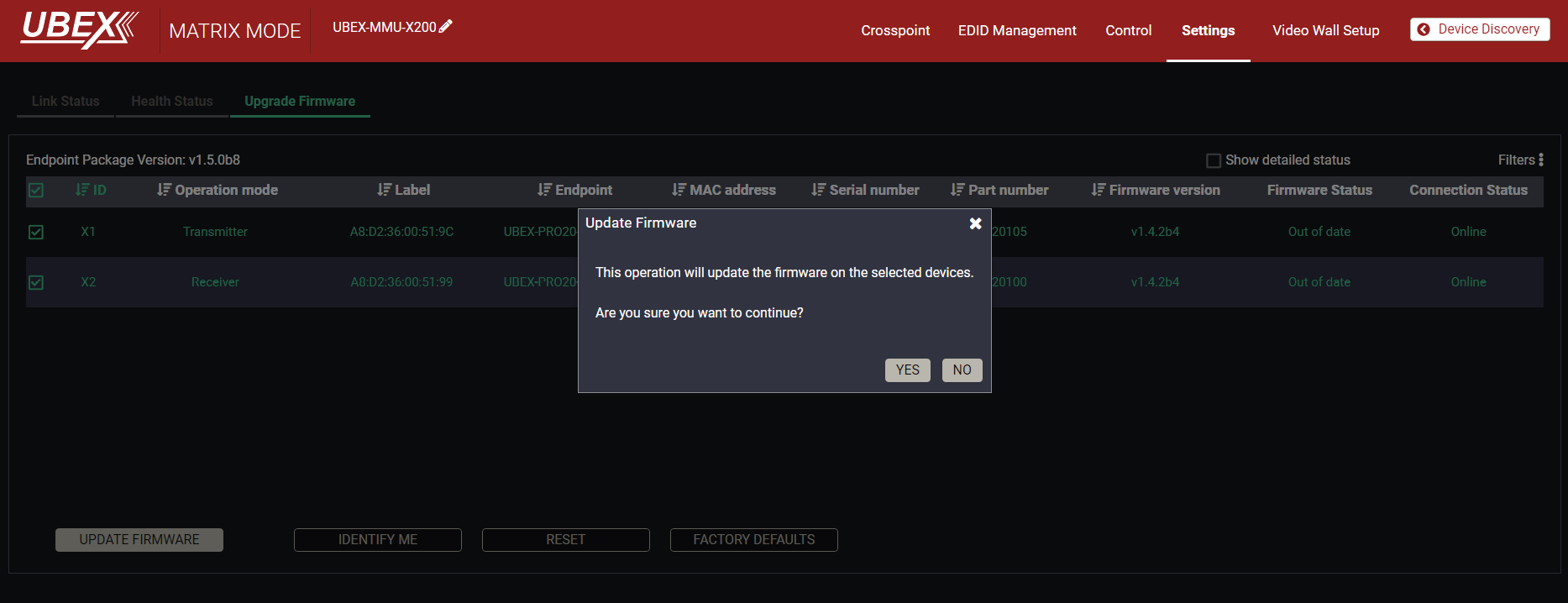
Pop-up message
After selecting Yes, the update procedure starts immediately. The actual status of each endpoints is shown in percent under the Firmware Status section. Clicking on the Show detailed status the last received text based message is shown.
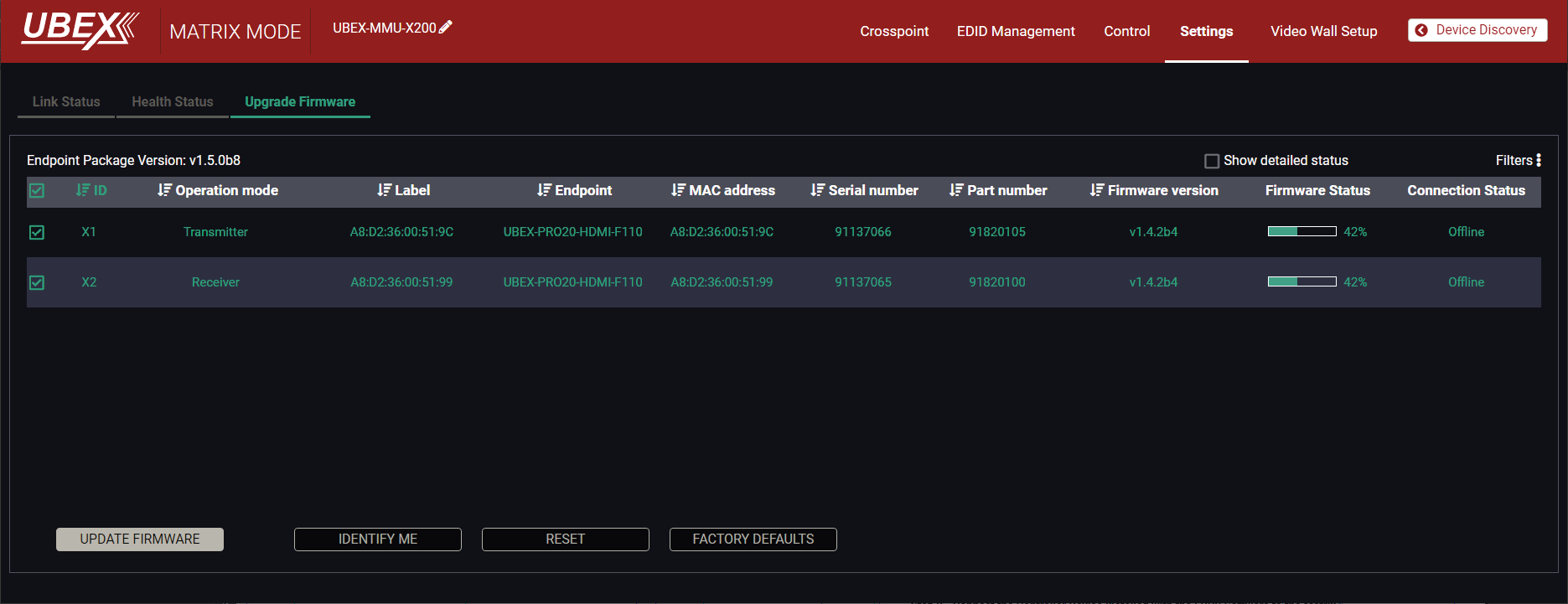
Firmware update is in progress
INFO:The devices might reboot several times during the firmware update procedure.
INFO:The percent counter can be changed to "Waiting for device" description in few times during the update. In this case the endpoint device performs internal procedures and it is the part of the normal operation.
Step 3.Wait until the units reboot with the new firmware.
Once the firmware update procedure is completed, the units reboot with the new firmware.
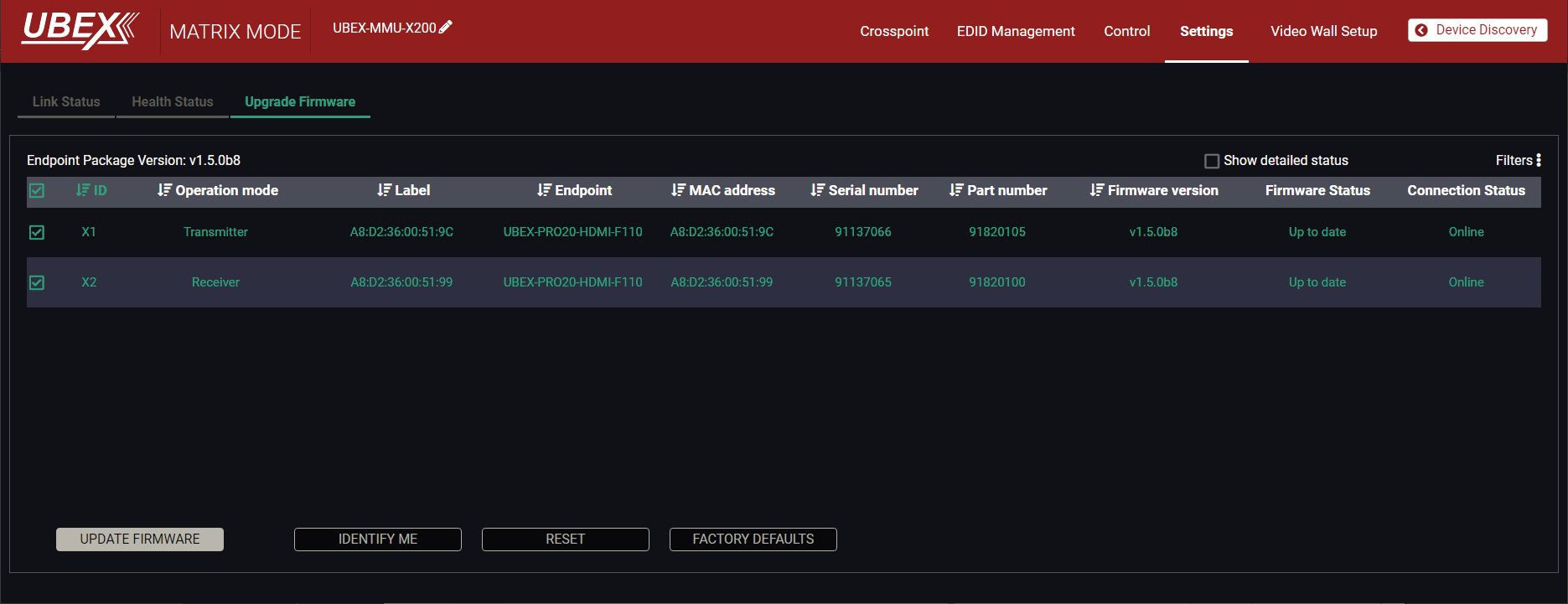
Firmware update procedure is done
INFO:The reclaiming procedure of the MMU takes a while, the "Up to date" firmware status may delayed a little bit because of this.
11.6. Endpoint Update - Manual Method
The following instructions belong to the endpoint devices (UBEX-PRO20-HDMI-F100 / F110 /F111 / F120 / F121 / R100 series) only. For the updating of the MMU see the Updating via GUI - MMU section.
ATTENTION!This update is not backward compatible with the version running on some endpoints. After updating these endpoints cannot be downgraded to versions prior to v1.4.0.
DIFFERENCE:Lightware highly recommends using the same and cohesive firmware versions on the UBEX extenders and the MMU. Connection between extenders installed with different versions might cause unexpected performance failures. See the list of cohesive endpoint and MMU firmware versions in the Endpoint Firmware Packages in the MMU section.
The Steps of the Preparing in Quick Summary
The endpoint devices are required to be prepared before the firmware updating. The steps are the following:
Step 1.Connect all endpoint devices and the MMU to the L3 network switch.
Step 2.Connect the controller device installed with the LDU2 software to the matrix.
Step 3.Set the IP addresses of the endpoint devices via LDC software or LW3 protocol commands.
Step 4.Set all endpoints to bootload (service / firmware update) mode via front panel LCD menu or using LW3 protocol commands.
The Steps of the Update in Quick Summary:
Step 1.Select the firmware package file.
Step 2.Select the units for updating.
Step 3.Check the update parameters.
Step 4.Start the update and wait until it is finished.
Step 5.Wait until the units reboot with the new firmware.
11.6.1. The Steps of the Preparing - Detailed Instructions
Step 1 - Connect All Endpoint Devices and the MMU to the L3 Network Switch.
See more details about it in the Connections section.
Step 2 - Connect the Controller Device Installed with the LDU2 Software to the Matrix.
The connection can be established via the network switch or the MMU as well. Do not connect the controller device to any endpoint.
Step 3 - Set the IP Addresses of the Endpoint Devices.
Two possible methods are for completing it:
▪via Lightware Device Controller (LDC) software;
▪via using LW3 protocol commands.
Via LDC Software / Built-in Web
Connect to the MMU using one of the following methods:
▪Launch the Lightware Device Controller (LDC) software and select the UBEX-MMU-X200 device in the Device Discovery window. Connect to the MMU by clicking on the Connect button. See more details in the Establishing Connection section.
▪Open a web browser application and enter the IP address of the MMU. See more details in the Software Control - Built-in Web chapter.
Select a source or destination stream in the crosspoint area to open the properties section in the right side. Navigate to the Device tab and select the Device Properties button to open the device properties window.
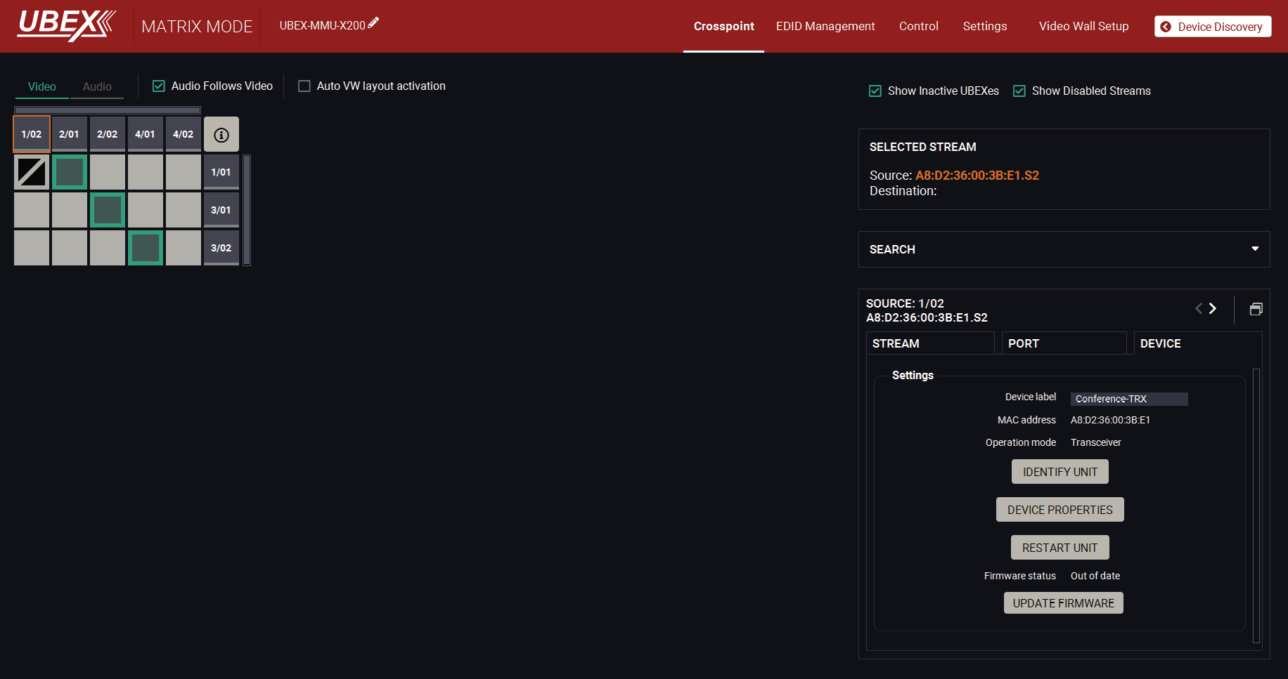
Crosspoint menu - Port properties section - Device tab in the LDC software
A pop window opens with the device properties. Navigate to the Settings menu and select the Network tab. Set the IP address of the endpoint device (static or dynamic (DHCP)).
ATTENTION!Always click on the Apply Changes button before closing the Device properties window.
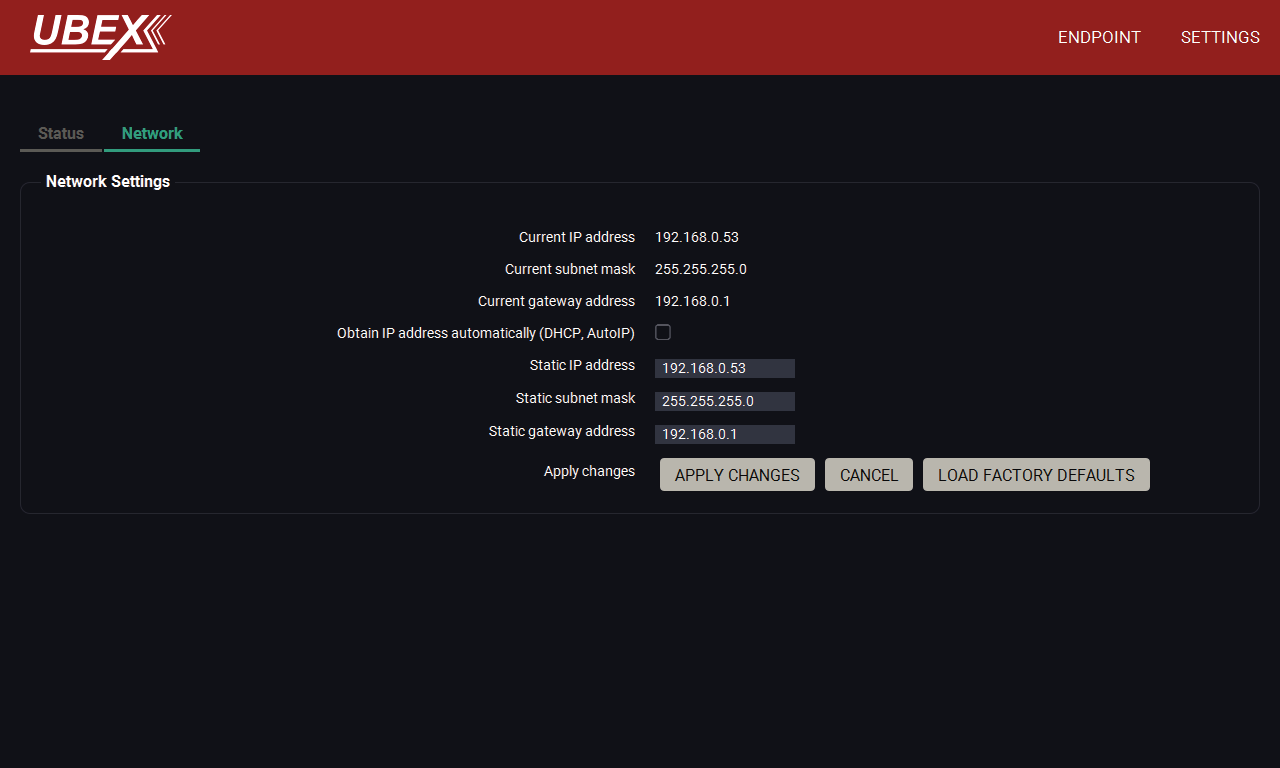
Device properties window - Settings menu - Network tab in the LDC software
ATTENTION!Make sure that all endpoint devices have different static IP addresses or the dynamic IP address (DHCP) is enabled in them to avoid the IP conflict.
Repeat the procedure with all endpoint devices which are wanted to be updated.
Via Using LW3 Protocol Commands
Connect to the MMU using a terminal application (e.g. Putty) or use the built-in Terminal of the LDC software / Built-in web. See more details in the Terminal Window section.
Type the following commands for enabling dynamic IP address (DHCP):
»SET /MEDIA/DEVICEMAP/<logical_device_ID>/MNT/MANAGEMENT/NETWORK.DhcpEnabled=true
»CALL /MEDIA/DEVICEMAP/<logical_device_ID>/MNT/MANAGEMENT/NETWORK:applySettings()
The <logical_device_ID> is the ID of the endpoint device, for example: X1, X2, X3, etc.
Example:
»SET /MEDIA/DEVICEMAP/X1/MNT/MANAGEMENT/NETWORK.DhcpEnabled=true
»CALL /MEDIA/DEVICEMAP/X1/MNT/MANAGEMENT/NETWORK:applySettings()
Repeat the procedure with all endpoint devices which are wanted to be updated.
Type the following commands for setting a static IP address:
»SET /MEDIA/DEVICEMAP/<logical_device_ID>/MNT/MANAGEMENT/NETWORK.StaticIpAddress=<IP>
»CALL /MEDIA/DEVICEMAP/<logical_device_ID>/MNT/MANAGEMENT/NETWORK:applySettings()
The <logical_device_ID> parameter is the ID of the endpoint device, for example: X1, X2, X3, etc. The <IP> parameter is the IP address which are wanted to be set on the endpoint device.
Example:
»SET /MEDIA/DEVICEMAP/X1/MNT/MANAGEMENT/NETWORK.StaticIpAddress=192.168.0.53
»CALL /MEDIA/DEVICEMAP/X1/MNT/MANAGEMENT/NETWORK:applySettings()
ATTENTION!Make sure that all endpoint devices have different static IP addresses or the dynamic IP address (DHCP) is enabled in them to avoid the IP conflict.
Repeat the procedure with all endpoint devices which are wanted to be updated.
Step 4 - Set All Endpoints to Bootload (Service / Firmware Update) Mode.
Two possible methods are for completing it:
▪via using LW3 protocol commands;
▪via front panel LCD menu.
Via Using LW3 Protocol Commands
Connect to the MMU using a terminal application (e.g. Putty) or use the built-in Terminal of the LDC software / Built-in web. See more details in the Terminal Window section.
Type the following commands to set the device to bootload mode:
»CALL /MEDIA/DEVICEMAP/<logical_device_ID>:bootload()
The <logical_device_ID> parameter is the ID of the endpoint device, for example: X1, X2, X3, etc. The <IP> parameter is the IP address which are wanted to be set on the endpoint device.
The device reboots and starts in bootload (service / firmware update) mode.
Example:
»CALL /MEDIA/DEVICEMAP/X1:bootload()
Repeat the procedure with all endpoint devices which are wanted to be updated.
Via Front Panel LCD Menu

Navigate to the System settings menu and select the Bootload mode option. Select Yes at the confirmation. The device reboots and starts in bootload (service / firmware update) mode.
11.6.2. Start the LDU2 Application and Follow the Steps
Discovering the Devices
After launching LDU2 the device discovery an empty window appears. Click on the Discover Devices button to start finding the Lightware devices on the network.
LDU2 welcome screen
Device List
When the discovery has completed, the devices available on the network are listed in the application.
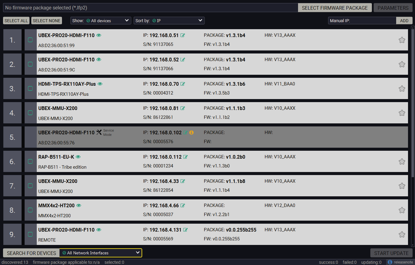
Legend of the Icons
|
|
IP address editor |
The IP address of the device can be changed in the pop-up window. |
|
|
Identify me |
Clicking on the icon results the front panel LEDs blink for 10 seconds which helps to identify the device phisically. |
|
|
Favorite device |
The device has been marked, thus the IP address is stored. When a device is connected with that IP address, the star will highlighted in that line. |
|
|
Further information available |
Device is unreachable. Change the IP address by pressing the IP address editor icon or use the front panel buttons (if available). |
|
|
Service mode |
The device is in bootload mode. Backup and restore cannot be performed in this case. |
Update Steps
Step 1.Select the firmware package.
Click on the Select Firmware Package button and navigate to the location where the LFP2 file of the UBEX endpoint is saved. When you click on the name of package, the preview of the release notes are displayed on the right side.
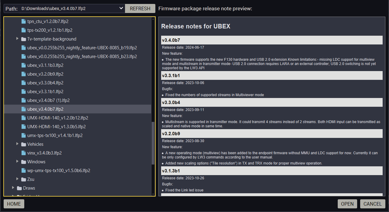
Firmware file browser and the release notes window
After the package file is loaded, the list is filtered to show compatible devices only. The current firmware version of the device is highlighted in orange if it is different from the version of the package loaded.
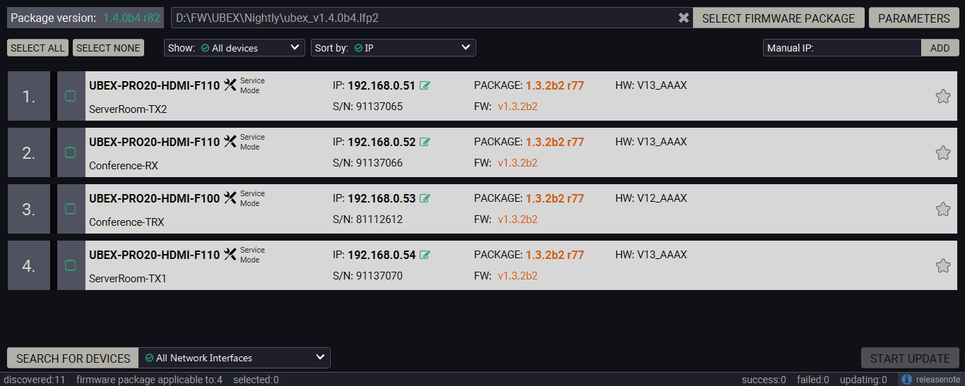
Filtered device list based on the selected firmware package
Step 2.Select the units for updating.
Pick the devices for updating. The selected lines will be highlighted in green.
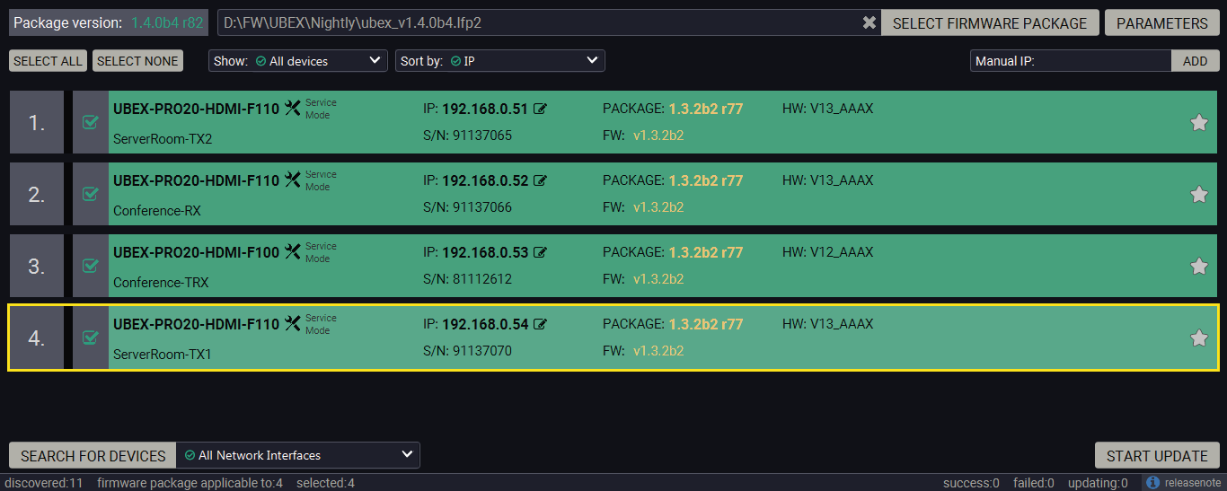
The units are selected for updating
TIPS AND TRICKS:If you are not sure which device is connected to your controller device directly, use the Identify me feature clicking on the button. It makes the four front panel LEDs blink in green for 10 seconds. The feature helps to identify the device itself in the rack shelf or on the desk.
Step 3.Check the update parameters.
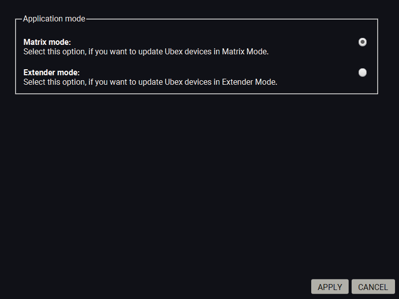
Click on the Parameters button to configure the firmware update.
Application Mode
The application mode (Extender or Matrix mode) of the current UBEX system can be selected in this section. Select the Matrix mode.
Click on the Apply button to save the settings.
Parameters menu for the UBEX endpoints
Step 4.Start the update and wait until it is finished.
Click on the Start Update button to start the procedure. The status is shown in percent in the right side of the device line and the status of the all procedures in the lower light green progress bar.
ATTENTION!This update is not backward compatible with the version running on some endpoints. After updating these endpoints cannot be downgraded to versions prior to v1.4.0.
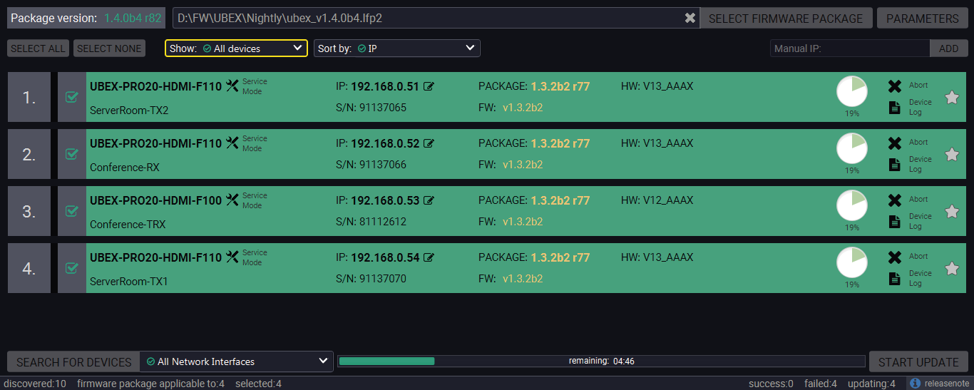
Firmware update is in progress
INFO:The devices might reboot several times during the firmware update procedure.
Step 5.Wait until the units reboot with the new firmware.
Once the firmware update procedure is completed, the units reboot with the new firmware.
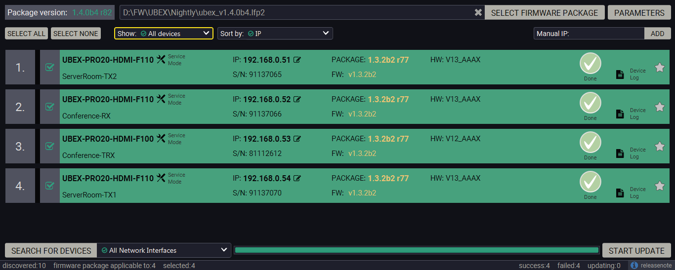
Firmware update procedure is done
11.7. Command Line Interface (CLI)
DIFFERENCE:The Command Line Interface is available from LDU2 v2.9.0b9.
The CLI of the LDU2 software is a simple tool for creating scriptable device updates without the need of human interactions. It allows batch updating with the same features that are available in case of GUI usage.
11.7.1. How to Run
Running under Windows® OS
The installer of LDU2 puts the following file into the installation folder:
LightwareDeviceUpdaterV2_CLI.cmd
CLI is available via this file, the exe is not suitable for that purpose. Open a command line window to execute or test the features directly.
Step 1.Open an Explorer window where the cmd file is located, the default is:
c:\Program Files (x86)\Lightware\Lightware Device Updater V2\LightwareDeviceUpdaterV2_CLI.cmd.
Step 2.Click on the address line (highlighed with blue in the picture), type cmd.exe and press enter. The command interpreter window of Windows is opened at the path of the LDU2 install folder.
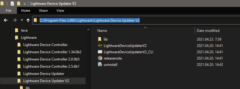
Step 3.Now you can use the LightwareDeviceUpdaterV2_CLI.cmd file with the commands and options, which are described in the coming sections:
Running under Linux
The Command Line Interface under Linux Operating Systems can be run by the following:
LightwareDeviceUpdaterV2.sh.
Running an update:
bash LightwareDeviceUpdaterV2.sh update --ip 172.24.5.27 --package ~/Downloads/ubex_v2.1.0b3.lfp2
The commands and options are the same under Windows® and Linux, too. Following sections contain examples with LightwareDeviceUpdaterV2_CLI.cmd.
11.7.2. How to Use
Command Structure
The commands can be run over CLI in the following way:
LightwareDeviceUpdaterV2_CLI.cmd [command] [options]
[Command]: a certain command described in the coming sections; only one command can be run at a time
[Options]: mandatory and/or optional parameters of the command, if any. Optional parameters have a default value, which can be found at each affected command. You only have to define the parameter if you want to apply a different value. The order of the options is arbitrary.
Important Notes
▪CLI is case-sensitive (including commands, options and other parameters).
▪There is no limit regarding the number of the devices to update. At most 20 devices are updated simoultaneously, when one of them is finished, the following (21st) will be started automatically.
▪If an update is failed, the IP address of the affected device(s) are listed at the end.
11.8. CLI Commands
INFO:The commands and options described in the following sections are the same under Windows® and Linux, too. The examples contain LightwareDeviceUpdaterV2_CLI.cmd.
About the Examples
▪Sent command is in blue, response is in grey.
▪If the response in practice is longer than listed in the example, this symbol can be seen: [...].
11.8.1. Help
The defined commands and options can be listed by the help command.
Command
LightwareDeviceUpdaterV2_CLI.cmd help
Example
C:\Program Files (x86)\Lightware\Lightware Device Updater V2>LightwareDeviceUpdaterV2_CLI.cmd help
C:\Program Files (x86)\Lightware\Lightware Device Updater V2>lib\jre\bin\java.exe -jar lib\ldu2.jar help
Command line usage:
Win: LightwareDeviceUpdaterV2_CLI.cmd [command] [options]
Linux: LightwareDeviceUpdaterV2.sh [command] [options]
Commands:
* help
* version
* update
* deviceInfo
* restore
* packageOptions
[...]
11.8.2. LDU2 Version
The response shows the version of the LDU2 and the version of the Script API (the Application Programming Interface that is used by the LDU2 and the script).
Command
LightwareDeviceUpdaterV2_CLI.cmd version
Example
C:\Program Files (x86)\Lightware\Lightware Device Updater V2>LightwareDeviceUpdaterV2_CLI.cmd version
C:\Program Files (x86)\Lightware\Lightware Device Updater V2>lib\jre\bin\java.exe -jar lib\ldu2.jar version
LDU2 version: 2.9.0b9
Script API version: 1.3.9
11.8.3. Check For New LDU2 Version
The following command can be used to check if an update of LDU2 is available. This is just a request, since the CLI is not suitable for handling the complete installer of the software.
Command
LightwareDeviceUpdaterV2_CLI.cmd checkForUpdates
Example 1
c:\Program Files (x86)\Lightware\Lightware Device Updater V2>LightwareDeviceUpdaterV2_CLI.cmd checkForUpdates
c:\Program Files (x86)\Lightware\Lightware Device Updater V2>lib\jre\bin\java.exe -jar lib\ldu2.jar checkForUpdates
Current LDU2 version: 2.9.1b1
LDU2 is up-to-date
Example 2
c:\Program Files (x86)\Lightware\Lightware Device Updater V2>LightwareDeviceUpdaterV2_CLI.cmd checkForUpdates
c:\Program Files (x86)\Lightware\Lightware Device Updater V2>lib\jre\bin\java.exe -jar lib\ldu2.jar checkForUpdates
Current LDU2 version: 2.9.1b1
New version is available online: v2.9.2b2
Download URL: http://update.lightware.hu/ldu2/lwr/v2.9.2b2/install_LDU2_v2.9.2b2.exe
11.8.4. Device Info
The most important information about the selected device is displayed; see the example for more details.
Command
LightwareDeviceUpdaterV2_CLI.cmd deviceInfo [options]
Options
|
Option |
Description |
Required? |
|
-i or --ip |
List of IP addresses of devices to be updated |
one of them is mandatory |
|
-n or --hostName |
List of host names of devices to be updated |
|
|
-v or --packageVersion |
Shows installed package version only |
optional |
Example 1
C:\Program Files (x86)\Lightware\Lightware Device Updater V2>LightwareDeviceUpdaterV2_CLI.cmd deviceInfo --ip 192.168.1.12
C:\Program Files (x86)\Lightware\Lightware Device Updater V2>lib\jre\bin\java.exe -jar lib\ldu2.jar deviceInfo --ip 192.168.1.12
Product name: UBEX-PRO20-HDMI-F100
IP address: 192.168.1.12
Serial number: 00002263
MAC address: a8:d2:36:ff:22:63
Part number: 91540065
Device label: 123
Package version: v1.3.0b6
CPU FW version: v1.3.0b3
HW version: V12_KAA0
Operation mode: Application mode
Example 2
C:\Program Files (x86)\Lightware\Lightware Device Updater V2>LightwareDeviceUpdaterV2_CLI.cmd deviceInfo --ip 192.168.1.12 --packageVersion
C:\Program Files (x86)\Lightware\Lightware Device Updater V2>lib\jre\bin\java.exe -jar lib\ldu2.jar deviceInfo --ip 192.168.1.12 --packageVersion
v1.3.0b6
11.8.5. Update
This command can be used to update the firmware of the devices.
Command
LightwareDeviceUpdaterV2_CLI.cmd update [options]
Options
|
Option |
Description |
Required? |
|
-p or --package |
The path of the firmware package file |
yes |
|
-i or --ip |
List of IP addresses of devices to be updated |
one of them is mandatory |
|
-n or --hostName |
List of host names of devices to be updated |
|
|
-b or --backupFolder |
Folder to create device configuration backup at. Default: USER_HOME/.ldu2/backup |
optional |
|
-f or --factoryDefault |
Apply factory reset during device update. Default: false |
optional |
|
-r or --reportProgress |
Report update progress in percentage form. Default: false |
optional |
|
Package-specific options |
Certain LFP2 packages have features that can be applied at this command; see the Package Options section. |
optional |
ATTENTION!The configuration is restored automatically if the factory default option is not applied in the update command.In that case, there is no need to run the restore command after the update.
Example
C:\Program Files (x86)\Lightware\Lightware Device Updater V2>LightwareDeviceUpdaterV2_CLI.cmd update --ip 192.168.1.12 --package C:\Firmwares\ubex_v2.1.0b3.lfp2 --reportProgress
C:\Program Files (x86)\Lightware\Lightware Device Updater V2>lib\jre\bin\java.exe -jar lib\ldu2.jar update --ip 192.168.1.12 --package C:\Firmwares\ubex_v2.1.0b3.lfp2 --reportProgress
[2021-05-12 08:59:36.336] [ INFO] [ main] - Device IPs: [192.168.1.12]
[2021-05-12 08:59:39.409] [ INFO] [ main] - All the selected devices are accessible over the network.
[2021-05-12 08:59:39.628] [ INFO] [ main] - All the selected devices are compatible with the specified package.
[2021-05-12 08:59:40.025] [ INFO] [ 192.168.1.12] - Package version: 1.3.2b3
[2021-05-12 08:59:40.092] [ INFO] [ 192.168.1.12] - Login functionality is currently not enabled.
[2021-05-12 08:59:40.129] [ INFO] [ 192.168.1.12] - Creating backup of device settings...
[2021-05-12 08:59:43.582] [ INFO] [ 192.168.1.12] - Backup HTTP enable properties
[2021-05-12 08:59:44.638] [ INFO] [ProgressReporter] - Progress: 2%
[2021-05-12 08:59:46.111] [ INFO] [ 192.168.1.12] - HTTP and HTTP post have got enabled on port 80
[2021-05-12 08:59:46.319] [ INFO] [ 192.168.1.12] - No miniweb file is found on the device.
[2021-05-12 08:59:48.890] [ INFO] [ 192.168.1.12] - HTTP and HTTP post properties have got restored on port 80
[2021-05-12 08:59:48.897] [ INFO] [ 192.168.1.12] - Switching device into bootload mode...
[2021-05-12 08:59:49.640] [ INFO] [ProgressReporter] - Progress: 5%
[...]
The lines containing "ProgressReporter" can be enabled optionally. If it is enabled, the current state is displayed every 5 seconds.
Restores device configuration from a backup file.
TIPS AND TRICKS:This command can be used for uploading a configuration to numerous devices (aka Configuration cloning by CLI).
Command
LightwareDeviceUpdaterV2_CLI.cmd restore [options]
Options
|
Option |
Description |
Required? |
|
-i or --ip |
List of IP addresses of devices to be updated |
one of them is mandatory |
|
-n or --hostName |
List of host names of devices to be updated |
|
|
-b or --backupFile |
The path of the configuration backup file |
yes |
|
-k or --keepOriginalIp |
Do not override the network settings of the device with the ones in the backup file. It comes in handy when multiple devices' configuration is being restored from a single backup file. Default: false |
optional |
ATTENTION!The configuration is restored automatically if the factory default option is not applied in the update command.In that case, there is no need to run the restore command after the update.
Example
C:\Program Files (x86)\Lightware\Lightware Device Updater V2>LightwareDeviceUpdaterV2_CLI.cmd restore --ip 192.168.1.12 --backupFile C:\mybackup.lw3 --keepOriginalIp
C:\Program Files (x86)\Lightware\Lightware Device Updater V2>lib\jre\bin\java.exe -jar lib\ldu2.jar restore --ip 192.168.1.12 --backupFile C:\mybackup.lw3 --keepOriginalIp
[2021-05-12 10:49:36.412] [ INFO] [ main] - Executing configuration restore...
[2021-05-12 10:49:36.425] [ INFO] [ main] - Device IPs: [192.168.1.12]
INFO:The firmware package checks the backup data before the restore procedure and if it is necessary, a conversion is applied to avoid incompatibility problems between the firmware versions. In that case, two backup files are created: the original and a new one with "_converted" suffix. Using the last one for restoring is recommended.
Shows package-specific update options.
Command
LightwareDeviceUpdaterV2_CLI.cmd packageOptions [options]
Options
|
Option |
Description |
Required? |
|
-p or --package |
The path of the firmware package file |
yes |
Example
C:\Program Files (x86)\Lightware\Lightware Device Updater V2>LightwareDeviceUpdaterV2_CLI.cmd packageOptions --package c:\Firmwares\ubex_v2.1.0b3.lfp2
C:\Program Files (x86)\Lightware\Lightware Device Updater V2>lib\jre\bin\java.exe -jar lib\ldu2.jar packageOptions --package c:\Firmwares\ubex_v2.1.0b3.lfp2
Backup and restore options:
--skipPresetsAtRestore : if true, device presets will not be restored. (Default: false)
--uploadDefaultMiniWeb : if true and no custom miniweb is present on the device, the default built-in miniweb will be uploaded to the device. (Default: false)
Test options:
--test : if true, no update will be performed, communication with the device will be tested. (Default: false)
Package option example can be seen in the following section.
11.8.8. Complex Examples
The following options applied:
▪Firmware is updated
▪Factory default settings restored
C:\Program Files (x86)\Lightware\Lightware Device Updater V2>LightwareDeviceUpdaterV2_CLI.cmd update --ip 192.168.1.12 --factoryDefault --package c:\Firmwares\ubex_v2.1.0b3.lfp2
C:\Program Files (x86)\Lightware\Lightware Device Updater V2>lib\jre\bin\java.exe -jar lib\ldu2.jar update --ip 192.168.1.12 --factoryDefault --package c:\Firmwares\ubex_v2.1.0b3.lfp2
[2021-05-12 11:22:09.089] [ INFO] [ main] - Device IPs: [192.168.1.12]
[2021-05-12 11:22:12.947] [ INFO] [ main] - All the selected devices are accessible over the network.
[2021-05-12 11:22:13.225] [ INFO] [ main] - All the selected devices are compatible with the specified package.
[2021-05-12 11:22:13.777] [ INFO] [ 192.168.1.12] - Package version: 1.3.2b3
[2021-05-12 11:22:13.878] [ INFO] [ 192.168.1.12] - Login functionality is currently not enabled.
[2021-05-12 11:22:13.896] [ INFO] [ 192.168.1.12] - Switching device into bootload mode...
[2021-05-12 11:22:34.519] [ INFO] [ 192.168.1.12] - Gathering UID information from device...
[2021-05-12 11:22:35.097] [ INFO] [ 192.168.1.12] - UID info - Device IP: 192.168.1.12 Product name: MX2-16x16-DH-8DPi-A-R Product part number: 91310068 Serial number: 00002263 Hardware version: V12_KAA0 MAC address: A8:D2:36:FF:22:63
[2021-05-12 11:22:35.589] [ INFO] [ 192.168.1.12] - Package version on device: 1.3.2b3 r44
[2021-05-12 11:22:35.626] [ INFO] [ 192.168.1.12] - Updating UBEX series application fw part 1...
[2021-05-12 11:22:36.123] [ INFO] [ 192.168.1.12] - [ubex.bin.ER_IROM1]'s current version on device: 1.3.1b1 r35
[2021-05-12 11:22:36.124] [ INFO] [ 192.168.1.12] - [ubex.bin.ER_IROM1]'s version in the package: 1.3.1b1 r35
[2021-05-12 11:22:52.439] [ INFO] [ 192.168.1.12] - [tps_tx200.bin.ER_IROM1]'s firmware version updated in FVS EEPROM.
[2021-05-12 11:22:52.442] [ INFO] [ 192.168.1.12] - Updating VS100TX fw...
[2021-05-12 11:22:52.920] [ INFO] [ 192.168.1.12] - [vs100_tx.bin]'s current version on device: 1.1.0b0 r0
[2021-05-12 11:22:52.921] [ INFO] [ 192.168.1.12] - [vs100_tx.bin]'s version in the package: 1.1.0b0 r63
[2021-05-12 11:23:06.423] [ INFO] [ 192.168.1.12] - [vs100_tx.bin]'s firmware version updated in FVS EEPROM.
[2021-05-12 11:23:06.425] [ INFO] [ 192.168.1.12] - Updating UBEX series application fw part 2...
[2021-05-12 11:23:06.903] [ INFO] [ 192.168.1.12] - [mx2.bin.ER_IROM2]'s current version on device: 1.3.1b1 r35
[2021-05-12 11:23:06.904] [ INFO] [ 192.168.1.12] - [mx2.bin.ER_IROM2]'s version in the package: 1.7.0b17 r35
[2021-05-12 11:23:27.858] [ INFO] [ 192.168.1.12] - [mx2.bin.ER_IROM2]'s firmware version updated in FVS EEPROM.
[2021-05-12 11:23:27.860] [ INFO] [ 192.168.1.12] - Updating PS171 FW...
[2021-05-12 11:23:28.338] [ INFO] [ 192.168.1.12] - [ubex_family_ps171.bin]'s current version on device: 1.0.6b0 r0
[2021-05-12 11:23:28.340] [ INFO] [ 192.168.1.12] - [ubex_family_ps171.bin]'s version in the package: 1.7.0b17 r522
[2021-05-12 11:23:44.810] [ INFO] [ 192.168.1.12] - [ubex_family_ps171.bin]'s firmware version updated in FVS EEPROM.
[2021-05-12 11:23:51.412] [ INFO] [ 192.168.1.12] - Setting system information...
[2021-05-12 11:23:57.994] [ INFO] [ 192.168.1.12] - Starting application...
[2021-05-12 11:25:44.239] [ INFO] [ 192.168.1.12] - Done
All 1 update(s) finished successfully.
11.8.9. Exit Codes
There is a return value in all cases, when a command run is finished. Currently, three codes are defined:
|
Code |
Displayed text |
Description |
|
0 |
N/A |
The update performed successfully |
|
1 |
Update error (ErrorCode:1) |
The error happened during the update |
|
2 |
CLI error (ErrorCode:2 |
The error happened before starting the update |
The error line contains further information about the error.
Querying the Exit Code under Windows®
c:\Program Files (x86)\Lightware\Lightware Device Updater V2\echo %errorlevel%
0
Querying the Exit Code under Linux
echo $?
0
If this value is queried after the update and it is 0, the update performed successfully.
11.9. If the Update is not successful
▪Restart the process and try the update again.
▪If the device cannot be switched to bootload (firmware update) mode, you can do that manually as written in the User manual of the device. Please note that backup and restore cannot be performed in this case.
▪If the backup cannot be created for some reason, you will get a message to continue the process without backup or stop the update. A root cause can be that the desired device is already in bootload (firmware update) mode, thus the normal operation mode is suspended and backup cannot be made.
▪If an update is not successful, the Export log button becomes red. If you press the button, you can download the log file as a ZIP package, which can be sent to Lightware Support if needed. The log files contain useful information about the circumstances to find the root cause. #bootload
Usually, if the system seems not to transport the signal as expected, the best strategy for troubleshooting is to check signal integrity through the whole signal chain starting from source side and moving forward to receiver end.
At first, check front panel LEDs and take the necessary steps according to their states. For more information about status LEDs, refer to the Front and Rear View - F-series Endpoint Devices or Front and Rear View - R-series Endpoint Devices sections for the endpoint devices and to the Front and Rear View - UBEX-MMU-X200 section for the MMU.
Legend

|
Link to connections/cabling section. |

|
Link to device operation section. |

|
Link to LDC software section. |

|
Link to LW3 protocol commands section. |

|
Link to Switchable USB protocol commands section. |
|
Symptom |
Root cause |
Action |
Refer to |
|
|---|---|---|---|---|
|
Video signal |
||||
|
No picture on the video output |
Device or devices are not powered properly |
Check the endpoints, the MMU, the network switch, and the other devices if they are properly powered; try to unplug and reconnect them. |

|
|
|
Cable connection problem |
Cables must fit very well, check all the connectors (HDMI and optical/DAC cables). |

|
||

|
||||
|
Optical cable became contaminated |
Use special fiber optical cable cleaning equipment to clean it carefully. |
|||
|
Incorrect settings are applied in the network switch |
Check the configuration settings of the network switch. See more typical switch related issues on the next page. |

|
||
|
Singlemode-multimode SFP / SFP+ module pairs |
Check the installed SFP / SFP+ modules and install multimode or singlemode modules by pairs only. |

|
||
|
SFP module is installed instead of SFP+ module |
Install SFP+ transceiver module to the SFP+ port |

|
||
|
Incorrect optical cabling of the SFP+ modules or Neutrik opticalCON connectors |
Check the cabling of the modules or connectors |

|
||
|
Video signal |
||||
|
Incompatible SFP+ modules are in the endpoint and the network switch |
Check the compatibility of the installed SFP+ modules: singlemode / multimode pairs, parameters of the modules |

|
||
|
Different lengths of copper cables are applied for the SFP+ to RJ45 modules |
Install equal lengths for both copper Ethernet cables |
|
||
|
Not the proper video stream is the active one |
Check the crosspoint state which video stream switched to the current output. |

|
||

|
||||
|
No picture on the video output |
Video stream is disabled |
Enable the source stream. |

|
|
|
|
||||
|
Output port is disabled |
Enable the destination stream. |
|
||
|
|
||||
|
Display is not able to receive the video format |
Check the emulated EDID; select another (e.g. emulate the EDID of the display on the input port). |

|
||

|
||||
|
Display is not able to display the video format |
Scale the stream on HDMI in 1 and 2 ports of the transmitter or HDMI in 2 port of the transceiver to the resolution and refresh rate of the sink device. |

|
||

|
||||
|
Display is not able to display the video format |
Scale the stream on the HDMI out 1 port of the receiver or HDMI out 2 port of the transceiver to the resolution and refresh rate of the sink device. |

|
||

|
||||
|
HDCP is disabled (TX) |
Enable HDCP on the TX input ports. |
|
||
|
|
||||
|
HDCP is disabled (RX) |
Enable HDCP on the RX output ports. |
|
||
|
|
||||
|
Not the desired picture displayed on the video output |
Video output is set to test pattern (no sync screen) statically (RX) |
Check No sync screen settings in the HDMI output properties (RX). |

|
|

|
||||
|
Video stream is switched to another output |
Check the crosspoint state. |

|
||

|
||||
|
Video signal |
||||
|
Colors of the video is incorrect |
Incorrect color space setting is active (TX) |
Check the color space settings on the TX side. |
|
|
|
|
||||
|
Incorrect color space setting is active (RX) |
Check the color space settings on the RX side. |
|
||
|
|
||||
|
Source locked mode cannot be set |
The resolution of the source stream and the sink device are not the same |
Set the scaler to passthrough mode or set the forced resolution to the same as the source stream's one. |
|
|

|
||||

|
||||
|
|
||||
|
Multiviewer |
||||
|
The tile does not appear on the canvas (multiviewer mode) |
The tile is disabled. |
Enable the tile. |
|
|

|
||||
|
The HDCP authentication failed, black screen appears in the tile. |
Set the HDCP-level to the correct one or check the content on the source side. |

|
||

|
||||
|
There is no input stream for the tile. |
Check video settings of the source. |
|
||
|
|
||||
|
The tile is beyond the canvas. |
Check the position of the tile. |
|
||
|
|
||||
|
The resolution of the source stream and the tile size is not the same. |
Check the resolution of the source stream. |
|
||
|
|
||||
|
Check the size of the tile. |
|
|||

|
||||
|
The color format of the input stream is YCbCr but multiviewer supports RGB only. |
Check the color space setting of the source stream. |

|
||

|
||||
|
Audio signal |
||||
|
No audio is present on output |
Source audio volume is low or muted |
Check the audio settings of the source. |
||
|
The incoming audio signal is unsupported |
Query the status of the audio output port and select a supported signal source |

|
||
|
The analog audio output port is muted |
Check the analog audio output port properties |
|
||
|
|
||||
|
Volume of the analog audio port is set low |
Check the analog audio input/output port properties |
|
||

|
||||

|
||||
|
|
||||
|
HDMI output signal contains no audio |
DVI EDID is emulated |
Check the EDID and select and HDMI EDID to emulate (the setting is available in the transmitter side). |

|
|

|
||||
|
Not the desired audio can be heard on the output |
Audio stream is switched to another output |
Check the audio crosspoint settings. |

|
|

|
||||
|
LDC returns with "HBR audio not supported" error message |
Currently installed LDC and firmware versions does not support HBR audio |
Update LDC, endpoint and MMU firmwares to the latest released version |

|
|
|
Network switch related issues * |
||||
|
No picture on the video output |
Link aggregation is not set in the switch. |
Create Link Aggregation Groups (LAG’s)/EtherChannels etc. for each port pair that is used. |

|
|
|
The picture is always dropped |
VLAN tagging is not set. |
Set the 286 VLAN ID and add all LAGs to this VLAN. |

|
|
|
Bandwidth problem on the network with a single 4K60 stream |
All streams are transmitted to all outputs because IGMPv2 snooping in not enabled. |
Enable IGMPv2 snooping. |

|
|
|
All streams are transmitted except the 4K60 one |
One of the 10G link cables is connected to another LAG. |
Check the LLDP and the status of the LAGs. |
|
|
|
All streams are transmitted except the 4K60 one |
Only one SFP+ module / DAC cable is installed in the endpoint device instead of two. |
Install two 10GbE SFP+ modules / DAC cables between the endpoint and the network switch |
|
|
|
Black stripes in the picture |
IGMPv2 snooping in not enabled. |
Enable IGMPv2 snooping. |

|
|
|
Optical cable became contaminated. |
Use special fiber optical cable cleaning equipment to clean it carefully. |
|||
|
Cable connection problem. |
Cables must fit very well, check all the connectors (video and optical/DAC cables). |

|
||

|
||||
|
* For more details about the configuration steps of the network switch with real-life examples please visit our website and download the application notes for UBEX: https://go.lightware.com/guide-for-UBEX |
||||
|
Network |
||||
|
No LAN connection can be established |
Incorrect IP address is set (fix IP) |
Use dynamic IP address by enabling DHCP option. |

|
|
|
|
||||
|
|
||||
|
Restore the factory default settings (with fix IP). |
|
|||
|
|
||||
|
|
||||
|
No LAN connection can be established |
IP address conflict |
Check the IP address of the other devices, too. |
||
|
Endpoint License issues |
||||
|
License is not accepted by the MMU |
Invalid license is tried to be uploaded |
Possibly another license has already been uploaded to the MMU. Remove it and try the uploading again. |

|
|

|
||||
|
The serial number of the recent MMU and the license's one does not match |
Check the serial number of the MMU and request another license file assigned to the correct device. |
|||
|
Non-license file is tried to be uploaded |
Check the file type and upload the license file to the MMU |

|
||
|
RS-232 signal - Endpoints |
||||
|
Connected serial device does not respond |
Cable connection problem |
Check the connectors to fit well; check the wiring of the plugs. |

|
|
|
|
||||
|
RS-232 settings are different |
Check the port settings of the endpoint and the connected serial device. |
|
||
|
|
||||
|
Messaging via serial port is not working |
Check the serial messaging rules and/or apply escaping in the message. |
|
||
|
|
||||
|
RS-232 signal - MMU |
||||
|
Connected serial device does not respond |
Cable connection problem |
Check the connectors to fit well; check the wiring of the plugs. |
|
|
|
|
||||
|
RS-232 settings are different |
Check the port settings of the MMU and the connected serial device. |
|
||
|
USB K+M (F120 and F121 models) |
||||
|
Not all keyboard/mouse keys are working with K+M |
Special function keys may not be supported in emulated mode |
Usage of ordinary keyboards built up to 104/105 keys and ordinary mice is recommended. |
|
|
|
Host cannot be controlled by the keyboard and the mouse |
The control mode is set to Local mode. |
Set the wished control mode. |

|
|

|
||||
|
USB KVM and USB 2.0 extension (F130 model) |
||||
|
Host cannot be controlled by the keyboard and the mouse |
The remote extender (REX) is not paired with the local extender (LEX). |
Pair the devices. |

|
|
|
Miscellaneous |
||||
|
I cannot find my endpoint device in the server room |
All AV boxes and gadgets look the same. |
Use the "Identify Me" feature. |

|
|
|
|
||||

|
||||
12.2. Network Diagnostics for UBEX Matrix
If any network related issues are detected during the operation of the UBEX Matrix, Lightware supports several useful tools to determine the root cause of the glitches. This section is about these tools.
12.2.1. Lightware Device Controller (LDC) Software
Lightware Device Controller (LDC) software has a built-in network analyzer tool in the Link Status Tab, located in the Diagnostics menu.
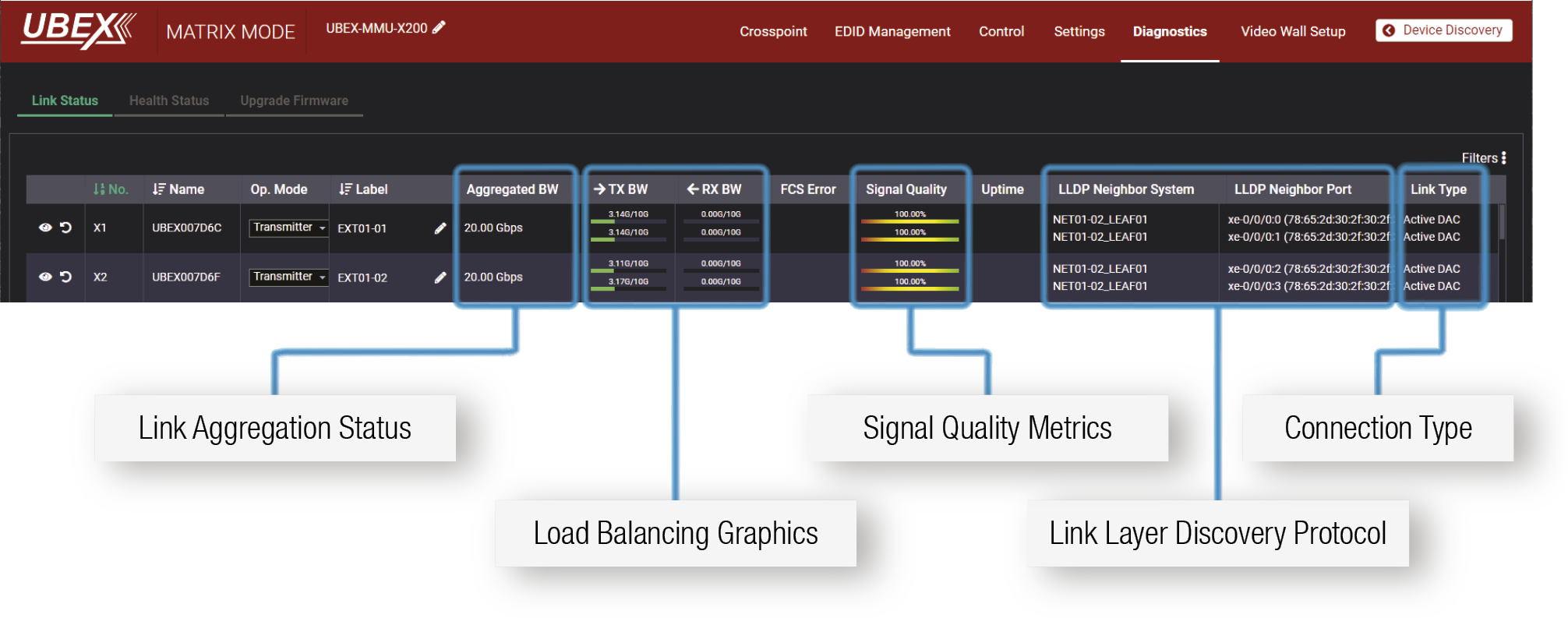
Link Status tab in the LDC software
Link Aggregation Status
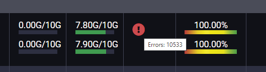
Link Aggregation shows the bandwidth used for both signal sources on both network links. FCS Error shows the number of broken network packages. If the counter keeps going up, the cable is unreliable. Signal quality shows the cable measured by the UBEX system on both links.
Load Balancing Graphics
The diagnostics surface provides easy to understand, icon based indication. This allows the operator to understand where are the potential network connection issues.
Legend of the Icons
|
UBEX connections are correct |
Network analyzing is required |
|||||
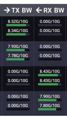
|
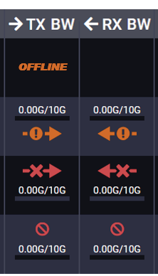
|
|||||
|
UBEX connection is OK |
UBEX cables disconnected, or both are in wrong LAG |
|||||
|
UBEX cable is in wrong LAG |
||||||
|
UBEX cable or the switch transceiver disconnected |
||||||
|
UBEX endpoint is disconnected |
||||||
Hardware Analysis - Cable or SPF+ Transceiver is Disconnected
If the Offline failure message (framed with blue) appears in the Load Balancing Graphics fields, it could be caused by a hardware issue in the network equipment. The following guide helps to determine which might be the possible root cause of this type of failure.
|
Switch side |
UBEX side |
||||||
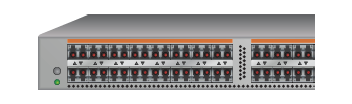
|
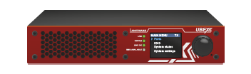
|
||||||
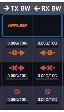
|
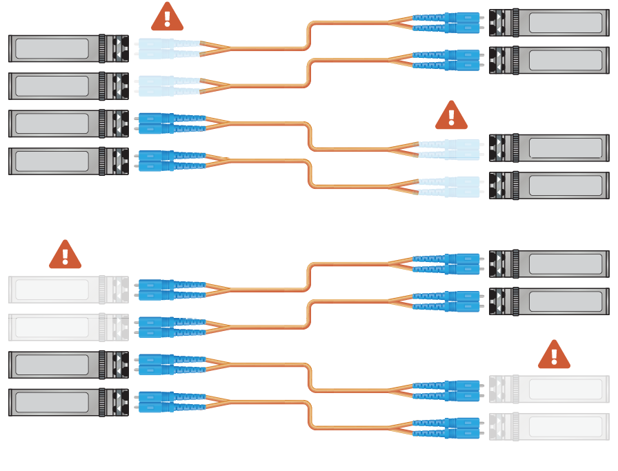
|
Optical cables on the switch side are disconnected. |
|||||
|
Optical cables on the UBEX endpoint side are disconnected. |
|||||||
|
SFP+ transceiver module(s) on the switch side are disconnected. |
|||||||
|
SFP+ transceiver module(s) on the UBEX endpoint side are disconnected. |
|||||||
Hardware Analysis - Wrong LAG Issue
Link aggregation (LAG) means the 2x 10G SFP+ channel of the endpoint is grouped to one united 20G channel. It requires setting both on the endpoint and the switch side. If the fiber optical cables are connected to different LAGs, it could cause network issues in the UBEX matrix.
|
Switch side |
UBEX side |
||||||
|
|
|
||||||
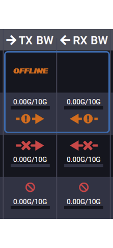
|
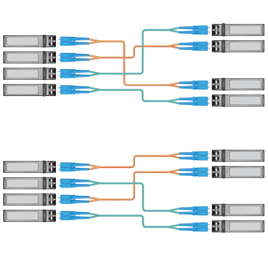
|
|
Green link connected first to a LAG. Orange link in a wrong LAG. |
||||
|
|
Both links are connected to already occupied LAGs. |
||||||
|
|
Green link connected first to a LAG. Orange link in a wrong LAG. |
||||||
|
|
Green link connected first to a LAG. Orange link in a wrong LAG. |
||||||
Hardware Analysis - Fiber Optical Channel Issues
A possible root cause of the network related issues can be that one channel of the duplex fiber optical cable has some failure or disconnected. In this case one direction of the data stream could loose IP packages or completely stop. Another signal loss root cause could be that one of the SFP+ transceiver modules on the switch or UBEX endpoint side has some failure and stops working.
|
Switch side |
UBEX side |
||||||
|
|
|
||||||
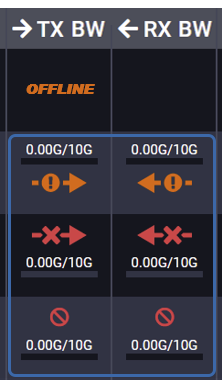
|
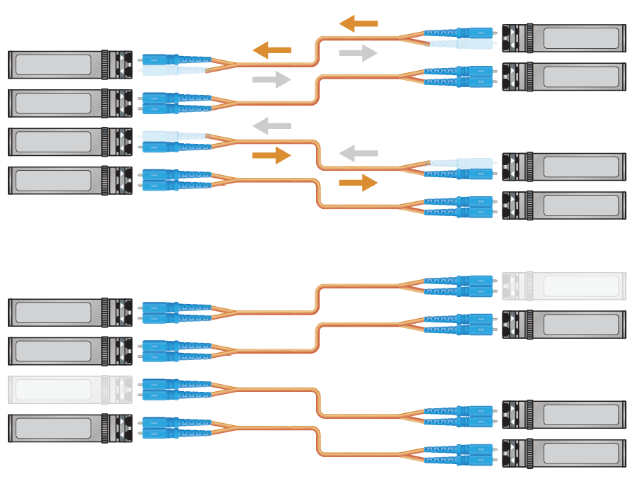
|
|
Switch transceiver right optical cable is disconnected. |
||||
|
|
Switch transceiver left optical cable is disconnected. |
||||||
|
|
SFP+ transceiver on the UBEX side is disconnected. |
||||||
|
|
SFP+ transceiver on the switch side is disconnected |
||||||
12.2.2. Front Panel LEDs and LCD Menu
Front Panel LEDs
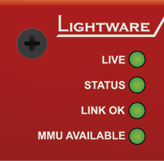
UBEX F-series and R-series endpoint devices give supportive feedback about the their network status, e.g. link aggregation, LACP and connection to the MMU. The full description about the LED operation can be found in the Front View section (front panel LED operation of the F-series and R-series endpoint devices are the same).
Front Panel LCD

When the front panel LEDs give feedback about network related issues, the users could check the details in the front panel LCD menu using the jog dial control knob. See more details about it in the Link Status section.
LAG Example for Status LED and LCD Feedback
The following example describes a connection drawing between a network switch and four UBEX endpoint devices with correct and incorrect LAG wirings.
▪Where both SFP+ link is connected to the same LAG of the switch, the total bandwidth will be 20 Gbps.
▪Where one of the SFP+ link is connected to a wrong LAG, LACP error appears and the total available bandwidth will be 10 or 0 Gbps.
ATTENTION!The LINK OK LED lights in all cases as the connection between the endpoint and the switch is up.
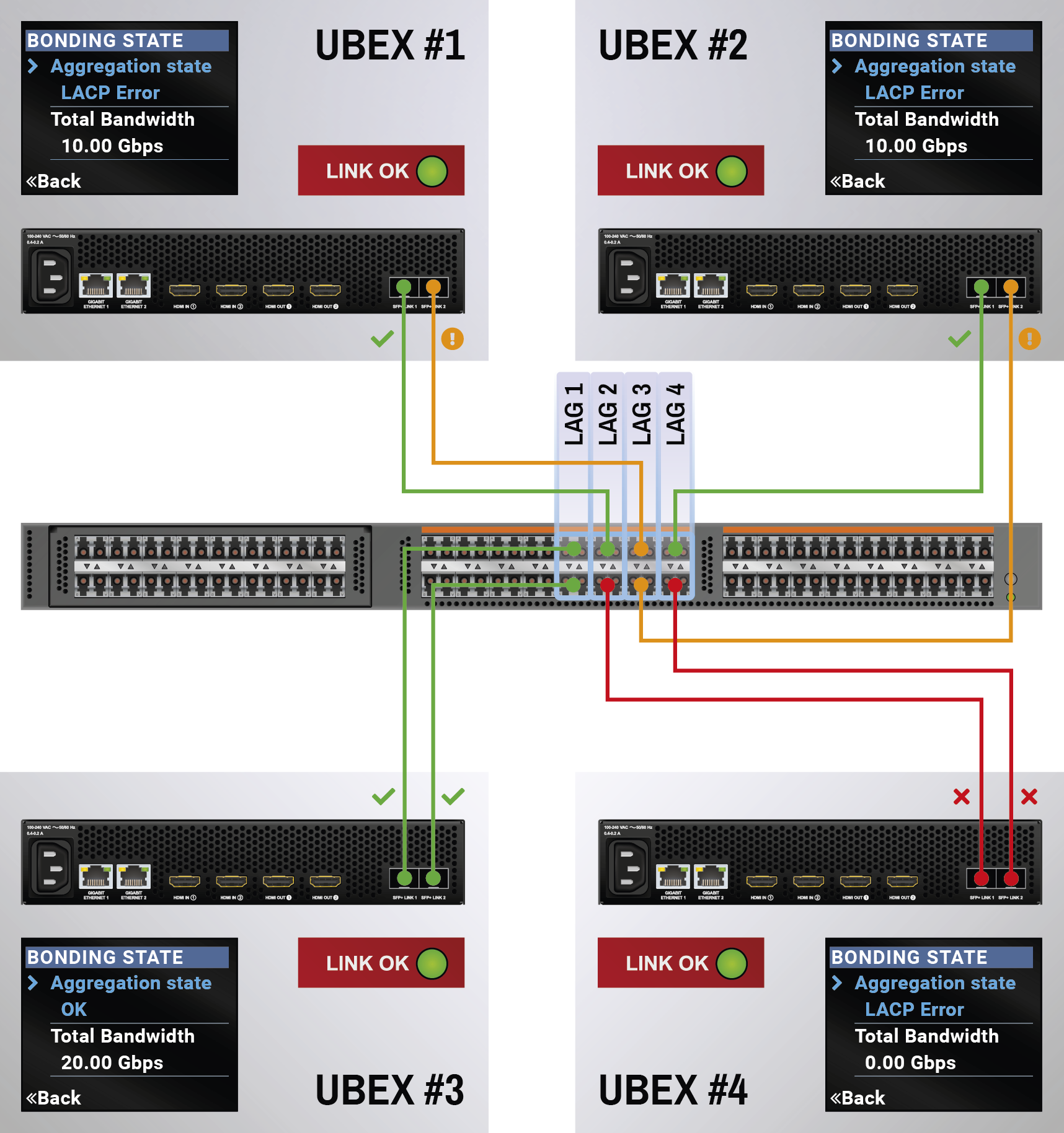
Example for One SFP+ Connection
SFP+ #1 is disconnected, but SFP+ #2 is connected to the switch with 10G connection.
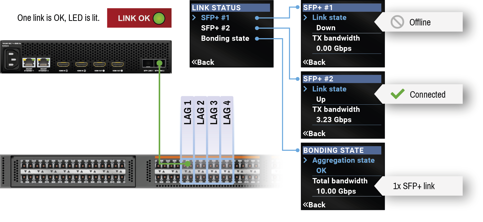
Example for Both SFP+ Connections in the Same LAG
SFP+ #1 and #2 are connected to the switch with 10G connections and they are in the same LAG, so the total available bandwidth is 20G.
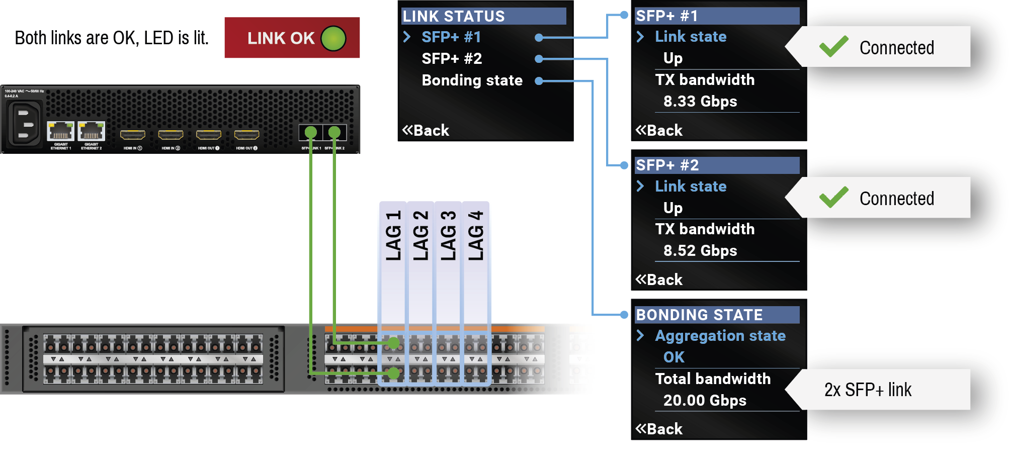
Example for LACP Error on One SFP+ Connection
SFP+ #1 and #2 are connected to the switch with 10G connections, but not the same LAG. SFP+ #2 is in Waiting for Aggregation state and the global aggregation state is LACP error. In this case the total available bandwidth is 10 Gbps.
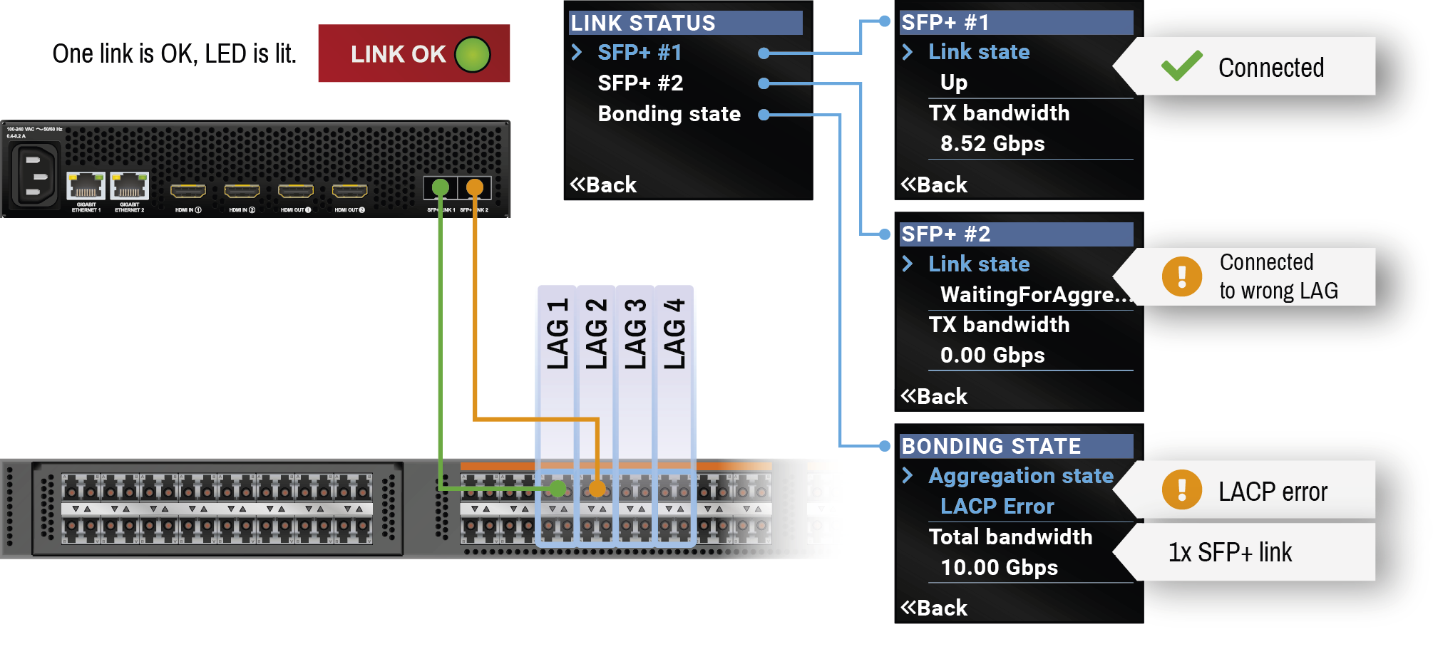
Example for LACP Error on Both SFP+ Connections
Both SFP+ links are connected to LAGs that belongs to other UBEX connections. Both SFP+ links show Waiting for Aggregation state and the global aggregation state is LACP error. In this case the total available bandwidth is 0 Gbps.
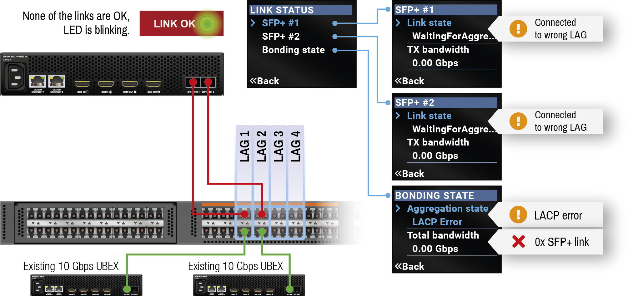
12.3. How to Speed Up the Troubleshooting Process
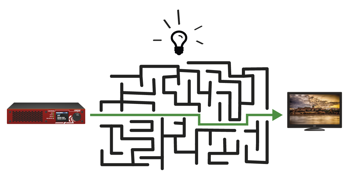
Lightware’s technical support team is always working hard to provide the fastest support possible. Our team’s response time is one of the best in the industry, and in the toughest of cases we can directly consult with the hardware or software engineer who designed the product, to get the information from the most reliable source.
However, the troubleshooting process can be even faster… with your help.
There are certain pieces of information that push us in the right direction to finding the root cause of the problem. If we receive most of this information in the first e-mail, or it is gathered at the time when you call us, then there is a pretty high chance that we will be able to respond with the final solution right away.
This information is the following:
▪Schematic (a pdf version is preferred, but a hand drawing is sufficient).
▪Serial number(s) of the device(s) (it is either printed somewhere on the box or you can query it in the Device Controller software or on the built-in website).
▪Firmware versions of the devices (please note that there may be multiple CPUs or controllers in the device and we need to know all of their firmware versions, a screenshot is the best option).
▪Cable lengths and types (in our experience, it’s usually the cable).
▪Patch panels, gender changers or anything else in the signal path that can affect the transmission.
▪Signal type (resolution, refresh rate, color space, deep color).
▪Emulated EDID(s) (please save them as a file and send it to us).
▪Actions to take in order to re-create the problem (if we cannot reproduce the problem, it is hard for us to find the cause).
▪Photo or video about the problem (‘image noise’ can mean many different things, it’s better if we see it too).
▪Error logs from the Device Controller software.
▪In the case of Event Manager issue, the event file and/or backup file from the Device Controller software.
The more of the above information you can give us, the better. Please send this information to the Lightware Support Team (support@lightware.com) to speed up the troubleshooting process.
The following sections contain descriptions and useful technical information on how the devices work in the background. The content is based on experiences and cases we met in practice. These sections help to understand features and technical standards like the following:
13.1.1. Understanding the EDID
The Extended Display Identification Data (EDID) is the passport of display devices (monitors, TV sets, projectors). It contains information about the capabilities of the display, such as supported resolutions, refresh rates (these are called Detailed Timings), the type and manufacturer of the display device, etc.
After connecting a source to a display (DVI, HDMI, DP), the source reads out the EDID to determine the resolution and refresh rate of the image to be transmitted.
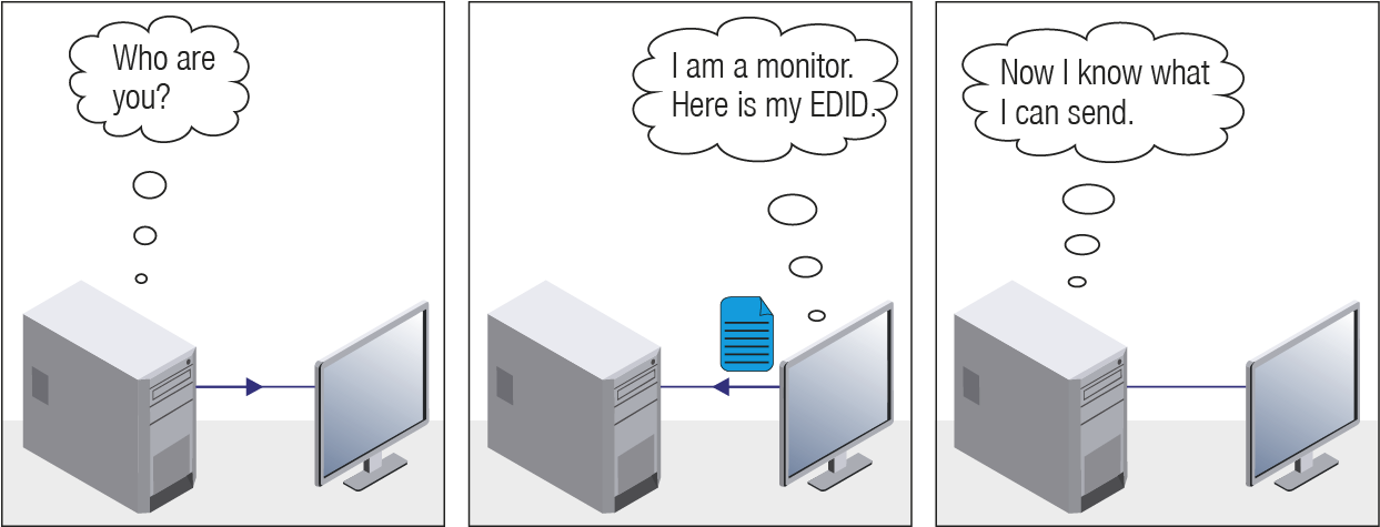
EDID Communication
Most DVI computer displays have 128-byte-long EDID structure. However, Digital Televisions and HDMI capable displays may have another 128 bytes, which is called E-EDID and is defined by CEA (Consumer Electronics Association). This extension contains information about additional Detailed Timings, audio capabilities, speaker allocation and HDMI capabilities. It is important to know that all HDMI capable devices must have CEA extension, but not all devices with CEA extension are HDMI capable.
Common Problems Related to EDID
Problem: “My system consists of the following: a computer, a Lightware device, a WUXGA (1920x1200) LCD monitor, and an SXGA (1280x1024) projector. I would like to see the same image on the monitor and the projector. What EDID should I choose on the Lightware device?”
Solution: If you want to see the image on both displays, you need to select the resolution of the smaller display (in this case SXGA), otherwise the smaller display may not show the higher resolution image.
Problem: “I have changed to a different EDID on an input port of the Lightware device to have a different resolution, but nothing happens.”
Solution: Some graphics cards and video sources read out the EDID only after power-up and later they do not sense that EDID has been changed. You need to restart your source to make it read out the EDID again.
13.1.2. Advanced EDID Management
Each DVI sink (e.g. monitors, projectors, plasma displays, etc...) must support the EDID data structure. Source BIOS and operating systems are likely to query the sink using DDC2B protocol to determine what pixel formats and interface are supported. DVI standard uses EDID data structure to identify the monitor type and capabilities. Most DVI sources (VGA cards, set top boxes, etc.) will output DVI signal after accepting the connected sink’s EDID information. In the case of EDID readout failure or missing EDID, the source will not output DVI video signal.
Lightware devices provide the Advanced EDID Management function that helps system integration. The built-in EDID Router can store and emulate factory pre-programmed- and User programmable EDIDs. The EDID of the attached monitors or projectors for each output are stored in a non-volatile memory. This way the EDID of a monitor is available when the monitor is unplugged or switched off.
Any EDID can be emulated on any input. An emulated EDID can be copied from the EDID router’s memory (static EDID emulation), or from the last attached monitor’s memory (dynamic EDID emulation). For example, the Lightware device can be set up to emulate a sink device, which is connected to one of the outputs. In this case, the EDID automatically changes, if the monitor is replaced with another display device (as long as it has a valid EDID).
EDID is independently programmable for all inputs without affecting each other. All inputs have their own EDID circuit.
INFO:The user is not required to disconnect the video cable to change an EDID as opposed to other manufacturer’s products. EDID can be changed even if a source is connected to the input and powered ON.
INFO:When EDID has been changed, the router toggles the HOTPLUG signal for 2 seconds. Some sources do not sense this signal. In such cases, the source device must be restarted or powered OFF and ON again.
Lightware Visual Engineering is a legal HDCP adopter. Several functions have been developed that help to solve HDCP related problems. Complex AV systems often have both HDCP and non-HDCP components. The matrix allows transmitting HDCP encrypted and unencrypted signals. The devices will be still HDCP compliant as they will never output an encrypted signal to a non-HDCP compliant display device. If an encrypted signal is switched to a non-compliant output, a red screen alert or muted screen will appear.
13.2.1. Protected and Unprotected Content
Many video sources send HDCP protected signal if they detect that the sink is HDCP capable – even if the content is not copyrighted. This can cause trouble if an HDCP capable device is connected between the source and the display. In this case, the content cannot be viewed on non-HDCP capable displays and interfaces like event controllers. Rental and staging technicians often complain about certain laptops, which are always sending HDCP encrypted signals if the receiver device (display, matrix router, etc.) reports HDCP compliancy. Even though, HDCP encryption is not required all the time (e.g. computer desktop image), certain laptops still do that.
To avoid unnecessary HDCP encryption, Lightware introduced the HDCP enabling/disabling function: the HDCP capability can be disabled in the Lightware device. If HDCP is disabled, the connected source will detect that the sink is not HDCP capable, and turn off authentication.
13.2.2. Disable Unnecessary Encryption
HDCP Compliant Sink
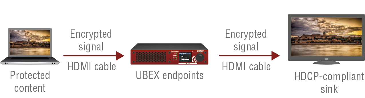
All the devices are HDCP-compliant, no manual setting is required, both protected and unprotected contents are transmitted and displayed on the sink.
Not HDCP-compliant Sink 1.
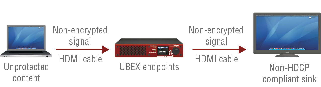
Non-HDCP compliant sink is connected to the endpoints. Some sources (e.g. computers) always send HDCP encrypted signals if the receiver device reports HDCP compliancy, however, HDCP encryption is not required all the time (e.g. computer desktop image). If HDCP is enabled in the endpoint, the image will not be displayed on the sink.
Setting the HDCP parameter to Auto on the output port and disable HDCP on the input port, the transmitted signal will not be encrypted if the content is not protected. Thus, non-HDCP compliant sinks will display non-encrypted signal.
Not HDCP-compliant Sink 2.
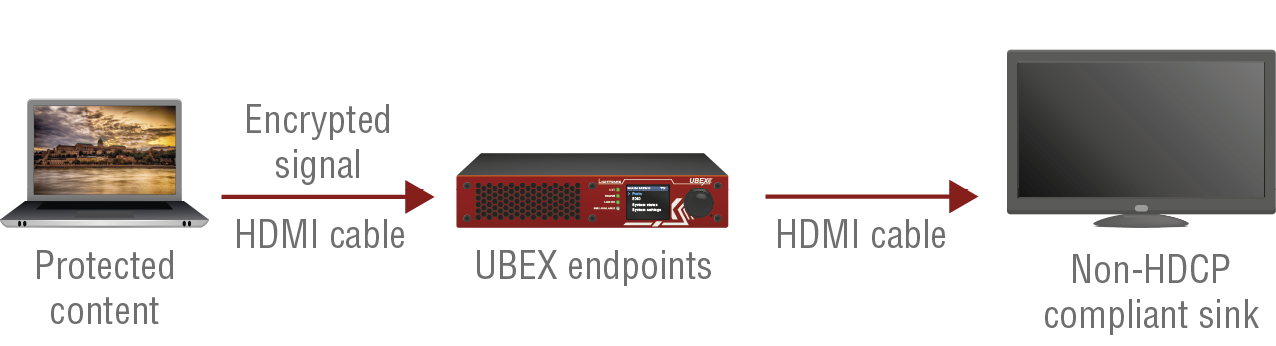
The layout is the same as in the previous case: non-HDCP compliant display device is connected to the endpoints but the source would send protected content with encryption. If HDCP is enabled on the input port of the endpoint, the source will send encrypted signal. The sink is not HDCP compliant, thus, it will not display the video signal (but blank/red/muted/etc. screen). If HDCP is disabled on the input port of the transmitter, the source will not send the signal. The solution is to replace the display device to an HDCP-capable one.
HDCP v2.2 is the latest evolution of copy protection. It is designed to create a secure connection between a source and a display. The 2.x version of HDCP is not a continuation of HDCPv1, and is rather a completely different link protection. One of the main differences is the number of the allowed devices within a closed A/V system: HDCP v2.2 allows 32 devices (HDCP v1.4 allows 128 devices). A further limit is that up to four level is allowed, which means the protected signal can be transmitted over at most four repeater/matrix/switcher device. HDCP content protection is activated only if an active video stream is transmitted from the source to the display. The encryption is not activated without a video signal.
HDCP v2.2 standard allows the application of a previous version of HDCP (e.g. HDCP v1.4) between the source and the display if the source device allows it. According to the standard, if the image content is protected with HDCP, the highest supported content protection level has to be applied. However, if the highest level of protection is not justified by the source content, the level may be decreased to avoid compatibility problems; this case is determined by the source.
HDCP v2.2 Source and HDCP v1.4 Sink
In this case the signal of an HDCP v2.2 compliant source is switched to an HDCP v1.4 compliant sink device. The signal is encrypted with HDCP v2.2 on the input and encrypted with HDCP v1.4 on the output of the Lightware device. A lower level of encryption may be applied only if the source device/content allows it - according to the HDCP standard. In this case the HDCP setting on the input port has to be set to HDCP 1.4 and depends on input on the output port.
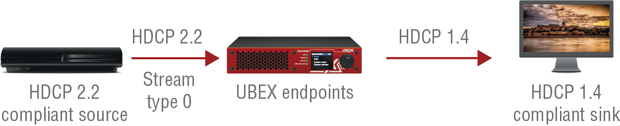
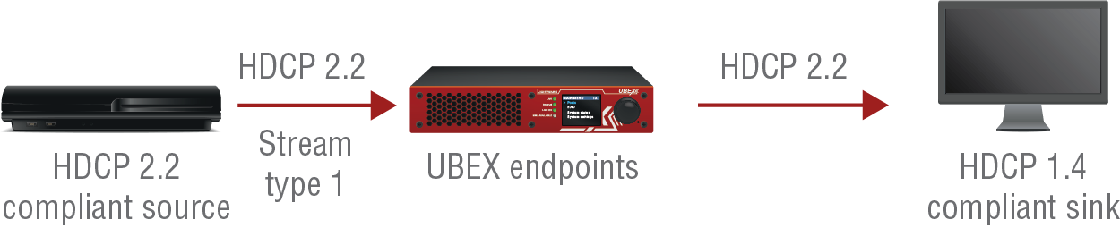
The content is Stream type 0
The content is Stream type 1 (High-value content)
HDCP v1.4 Source and HDCP v2.2 Sink
The example below is the reversal of the previous case. An HDCP v1.4 compliant source sends a signal with HDCP v1.4 encryption. The signal is switched to an HDCP v2.2 compliant sink device. In this case the outgoing signal has to be encrypted with the highest supported encryption level towards the sink, as the Lightware device and the sink are both HDCP v2.2 compliant. The HDCP v2.2 standard does not allow keeping the original HDCP v1.4 encryption level on the output.
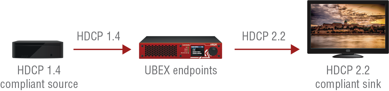
What Kind of Signal Will be on the Output of the Lightware Device?
See below table that summarizes the possible cases:
|
Incoming Signal |
HDCP v1.4 Compatible Sink |
HDCP v2.2. Compatible Sink |
|---|---|---|
|
HDCP v1.4 |
HDCP v1.4 |
HDCP v2.2 |
|
HDCP v2.2 (convertible)* |
HDCP v1.4 |
HDCP v2.2 |
|
HDCP v2.2 (not convertible)* |
Black screen |
HDCP v2.2 |
* Stream type 0: the video stream allows the conversion of the signal to apply a lower level of encryption.
** Stream type 1 (High-value content): the video stream does not allow the conversion of the signal.
13.3. Pixel Accurate Reclocking
Signal reclocking is an essential procedure in digital signal transmission. After passing the reclocking circuit, the signal becomes stable, jitter-free, and can be transmitted over more equipment like processors, or event controllers. Without reclocking, sparkles, noise, and jaggies appear on the image.
Lightware’s sophisticated Pixel Accurate Reclocking technology fixes more problems than general TMDS reclocking. It removes not only intra-pair skew, but inter-pair skew as well. The Pixel Accurate Reclocking circuit eliminates the following errors:
Intra-pair skew
Skew between the + and - wires within a differential wire pair (e.g. Data2- and Data2+). It’s caused by different wire lengths or slightly different wire construction (impedance mismatch) in the DVI cable. It results in jitter.

Inter-pair skew
Skew between two differential wire pairs in a cable. It is caused by different wire pair lengths or different number of twists in the DVI cable. Too much inter-pair skew results in color shift in the picture or sync loss.
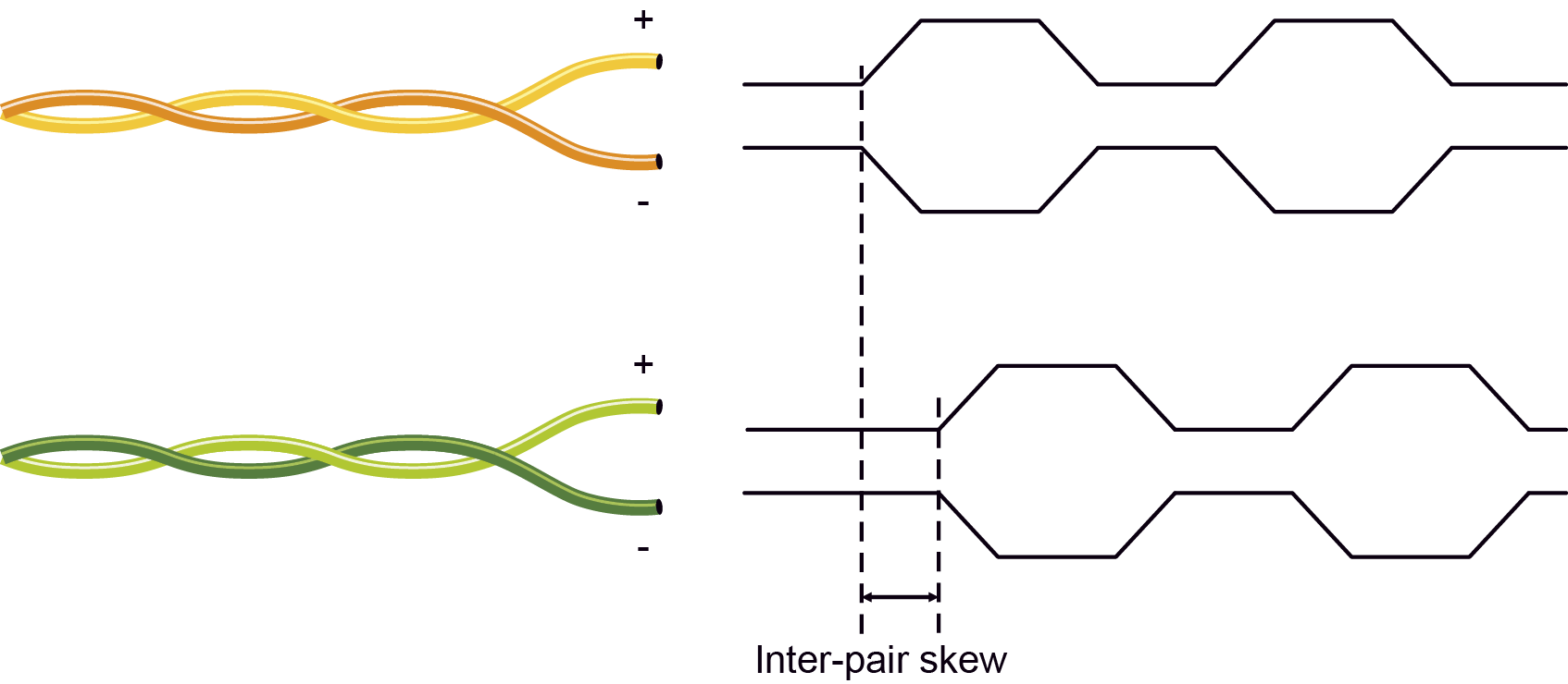
Jitter
Signal instability in the time domain. The time difference between two signal transitions should be a fixed value, but noise and other effects cause variations.

Noise
Electromagnetic interference between other electronic devices such as mobile phones, motors, etc. and the DVI cable are coupled onto the signal. Too much noise results in increased jitter.

INFO:The colors of the wire pairs in the pictures are for illustration and do not represent the color of the actual wires inside the cable.
13.4. AV Over IP
13.4.1. Basics
Besides the traditional AV matrix switchers and extenders, the AV over IP or networked AV system is the biggest leading technology in the AV industry. The spreading of the technology speeds up the general increase of the usage of the IT-related devices and equipment all around the world - from the offices to the homes.
The main difference compared to the traditional AV technologies is the method of the signal transmission: the networked AV transmitter/encoder devices convert the video signal to TCP/IP packets and transfer them to the receivers/decoders. The interface of the transmission can be CATx or fiber optical cable depending on the signal bandwidth and the distance between the source and sink devices.
13.4.2. What is TCP/IP?
DEFINITION:TCP/IP, or the Transmission Control Protocol/Internet Protocol, is a suite of communication protocols used to interconnect network devices on the Internet or in a private network.
TCP/IP specifies how data is exchanged over the network by providing end-to-end communications that identify how it should be broken into packets, addressed, transmitted, routed and received at the destination. TCP/IP requires little central management, and it is designed to make networks reliable, with the ability to recover automatically from the failure of any device on the network. *
The two main protocols in the Internet protocol suite serve specific functions. TCP defines how applications can create channels of communication across a network. It also manages how a message is assembled into smaller packets before they are then transmitted over the Internet and reassembled in the right order at the destination address. *
IP defines how to address and route each packet to make sure it reaches the right destination. Each gateway computer on the network checks this IP address to determine where to forward the message. *
* Source: https://searchnetworking.techtarget.com/definition/TCP-IP
13.4.3. Link Aggregation Protocol
The UBEX endpoints use Link Aggregation Control Protocol (LACP) to share the signal bandwidth of the streams equally between the two the SFP+ ports.
DEFINITION:The Link Aggregation Group (LAG) applies to various methods of combining (aggregating) multiple network connections in parallel in order to increase throughout beyond what a single connection could sustain.
The measurement of the bandwidth can happen via/using two different methods on the two interfaces:
▪HDMI pipes: the peak bandwidth is measured, which is the summary of the video burst (horizontal (H) blanking and vertical (V) blanking).
▪SFP+ links: the average bandwidth is measured.
Example for the Link Aggregation Protocol
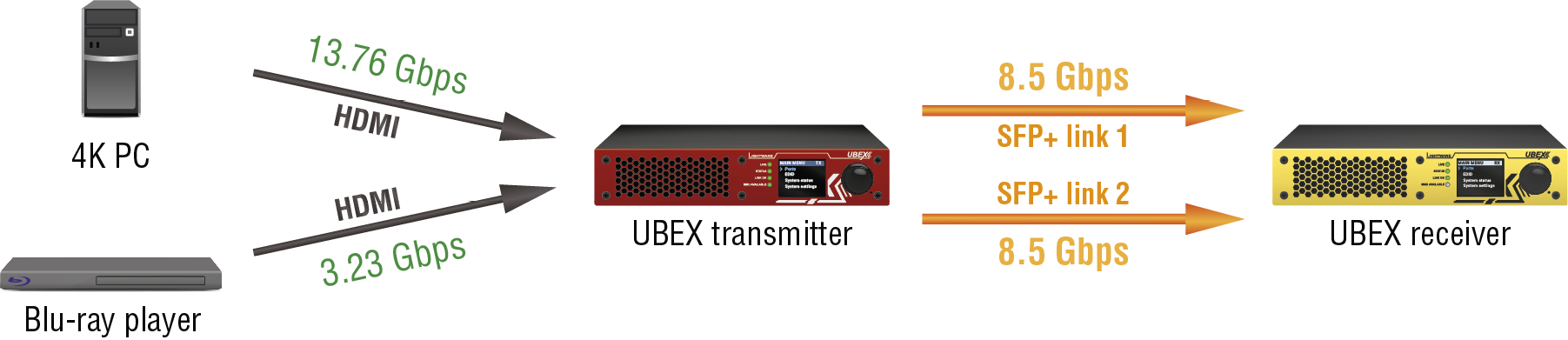
Example for the working of the LACP
13.4.4. Multicast DNS (mDNS) Protocol
The multicast DNS (mDNS - (multicast Domain Name System) protocol resolves host names to IP addresses within small networks that do not include a local name server. It is a zero-configuration service, using essentially the same programming interfaces, packet formats and operating semantics as the unicast Domain Name System (DNS). *
The primary benefits of using mDNS is that it requires little or no administration to set up. Unless the network is specifically configured to not allow mDNS, UBEX sources will be discovered. This format works when no infrastructure is present, and can span infrastructure failures.
* Source: https://en.wikipedia.org/wiki/Multicast_DNS
This chapter contains step-by-step assembly guides for the UBEX series devices like the following:
14.1. Front Plate Exchange for F-series Endpoint Devices
The section is about the assembling of the UBEX F-series endpoint devices that contains detailed step-by-step guides and the tool requirements.
Affected Models
The front plate can be changed on the following endpoint models:
▪UBEX-PRO20-HDMI-F100
▪UBEX-PRO20-HDMI-F110
▪UBEX-PRO20-HDMI-F111
▪UBEX-PRO20-HDMI-F120
▪UBEX-PRO20-HDMI-F121
▪UBEX-PRO20-HDMI-F130
14.1.1. Tool Requirements

|

|
|
|
Plastic spudger tool |
1.3 mm hex wrench (Allen) key |
PZ1 screwdriver |
14.1.2. The Steps of the Front Plate Exchange
Removal of the Front Plate
Step 1.Remove the rubber ring carefully from the jog dial knob using the plastic spudger tool.
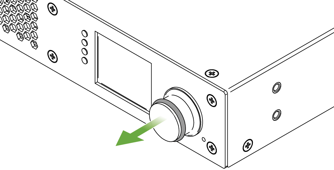
Step 2.Find the screw in the side of the jog dial knob and use a 1.3 mm hexagon (Allen) wrench key to loosen it.
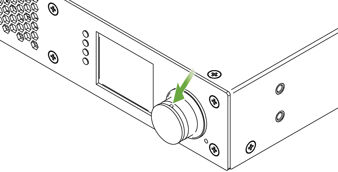
Step 3.Pull down the jog dial knob from the holder.
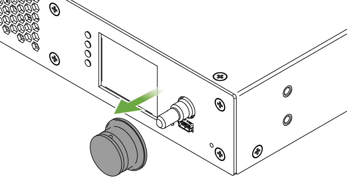
Step 4.Remove all six screws from the front plate using the PZ1 screwdriver.

Step 5.Remove the front plate from the chassis.
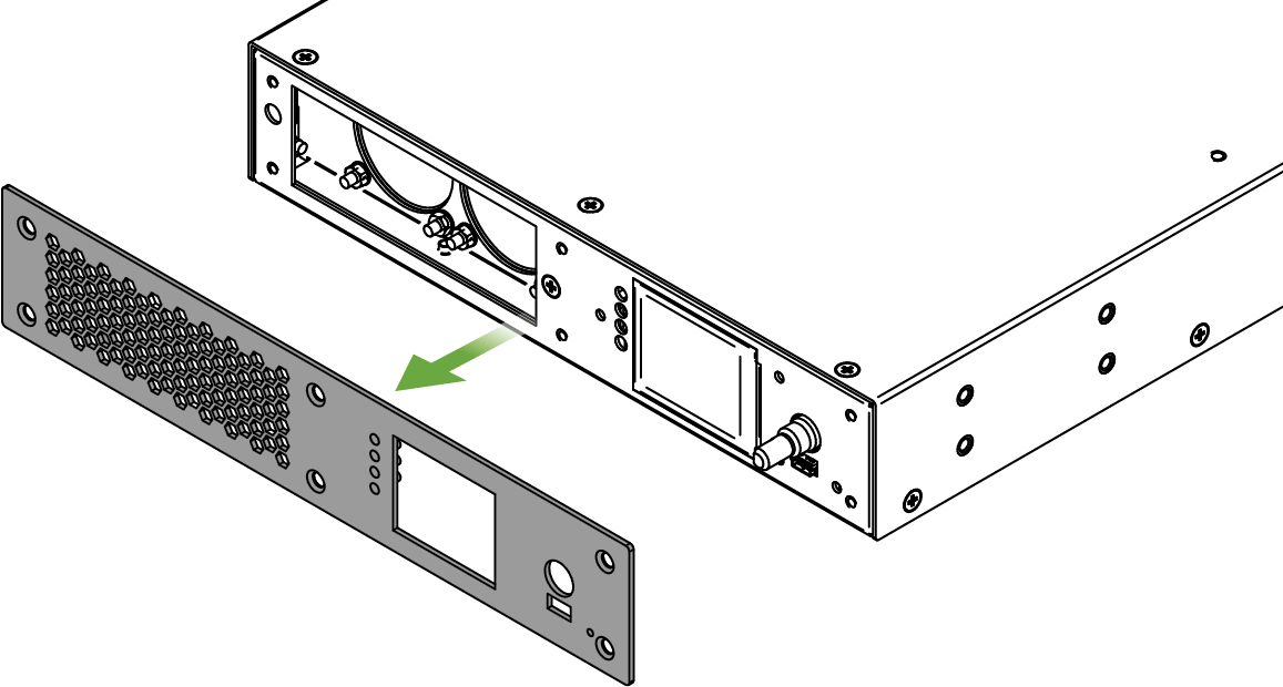
Step 6.Push out the four light pipes from the front plate starting from the rear side of the plate.
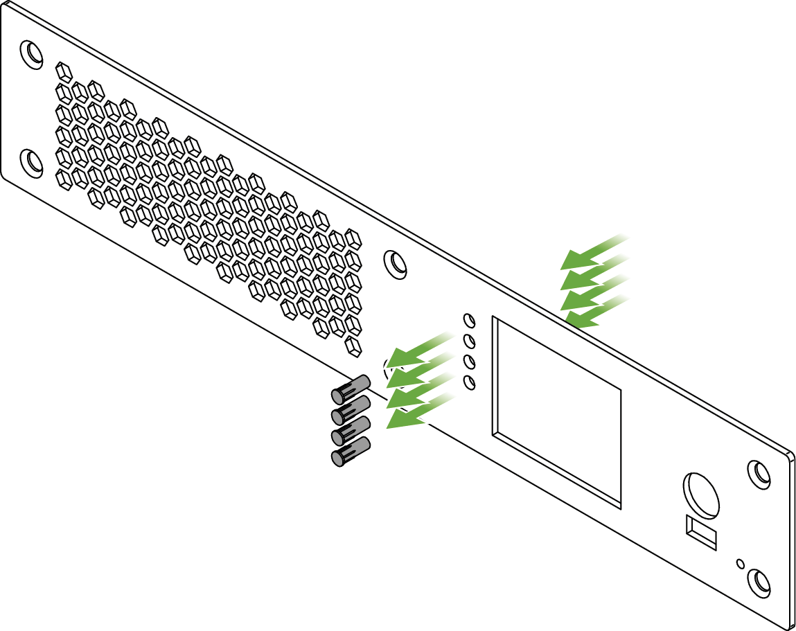
Insertion of the New Front Plate
Step 1.Insert the four light pipes to the new front plate starting from the front side of the plate. Take care of the direction of the light pipes.
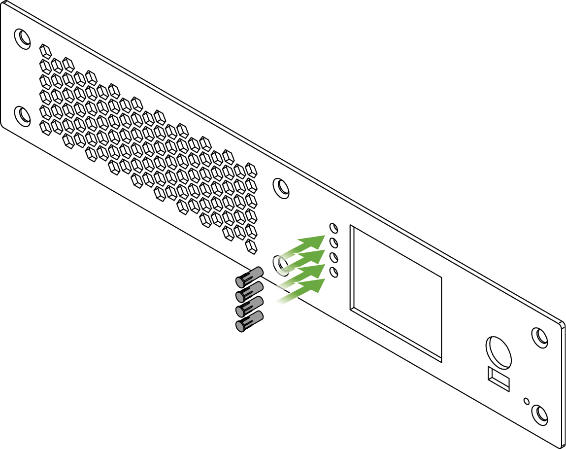
Step 2.Place the front plate on the chassis.
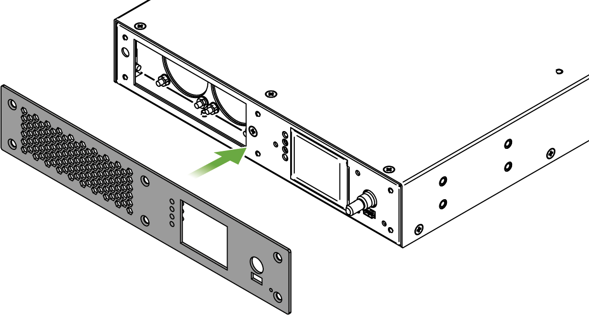
Step 3.Fasten all six screws on the front plate using the PZ1 screwdriver.
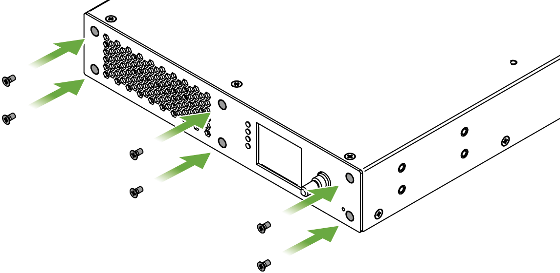
Step 4.Insert the jog dial knob to the holder so that the fixing screw hole shall be over the flat part of the holder.
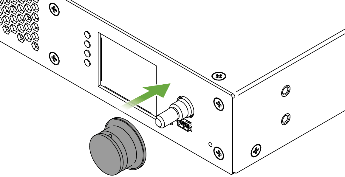
Step 5.Find the screw in the side of the jog dial knob and use a 1.3 mm hexagon (Allen) wrench key to fasten it.
Step 6.Place the rubber ring carefully on the jog dial knob.
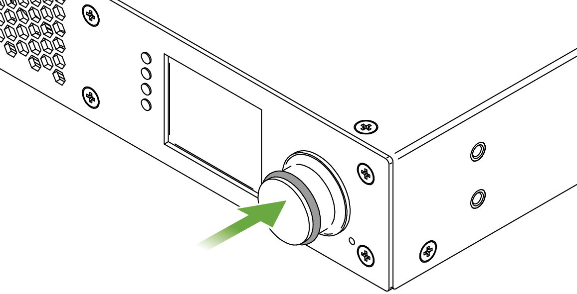
14.2. SFP+ Module Changing in R-series Endpoints
The R-series endpoint devices are built with pre-installed SFP+ modules inside the enclosure. The modules can be changed by the user in a few simple steps.
WARNING!Lightware highly recommends that the following operations to be done in ESD (Electrostatic Discharge) protected environment.
Affected Models
▪UBEX-PRO20-HDMI-R100 series
SFP+ Modules inside the Enclosure
|
Type of the SFP+ module |
Number of modules |
Optical Mode |
Wavelength |
|
|
2xMM-2xDUO |
Finisar FTLX8574D3BCL |
2 |
Multimode |
850 nm |
|
2xMM-QUAD |
Finisar FTLX8574D3BCL |
2 |
Multimode |
850 nm |
|
2xSM-2xDUO |
Finisar FTLX1475D3BCL |
2 |
Singlemode |
1310 nm |
|
2xSM-QUAD |
Finisar FTLX1475D3BCL |
2 |
Singlemode |
1310 nm |
|
2xSM-BiDi-DUO |
Module A: Finisar FTLX2072D327 |
1 |
Singlemode |
in: 1331 nm out: 1271 nm |
|
Module B: Finisar FTLX2072D333 |
1 |
in: 1271 nm out: 1331 nm |
Removal of the Original SFP+ Modules
Step 1.Disconnect the device from the power source.
WARNING!Never disassemble the device when it is connected to the power source. The unit is built with open frame power supply module, touching it when the device is under power is dangerous.
Step 2.Remove five screws with a PZ1 screwdriver from the left side of the device (highlighted below with green).
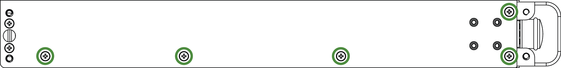
R-series endpoint device - left view
Step 3.Remove five screws from the right side of the device (highlighted below with green).
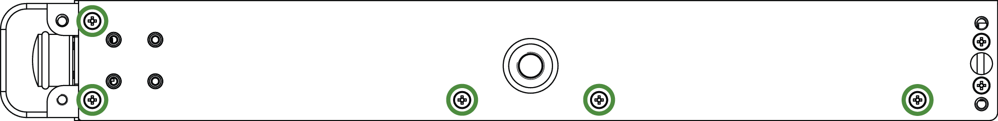
R-series endpoint device - right view
Step 4.Remove all five screws from the top cover of the device (highlighted below with green).
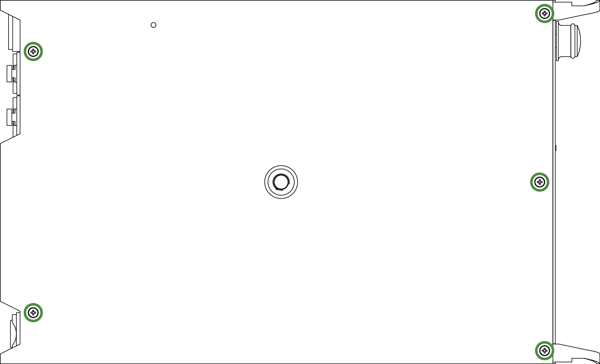
R-series endpoint device - top view
Step 5.Remove the top cover cautiously. Push the cover backwards a little, then remove it upwards.
ATTENTION!The protective ground cable is connected to the top cover. Be sure that the connection is not harmed when removing the cover.
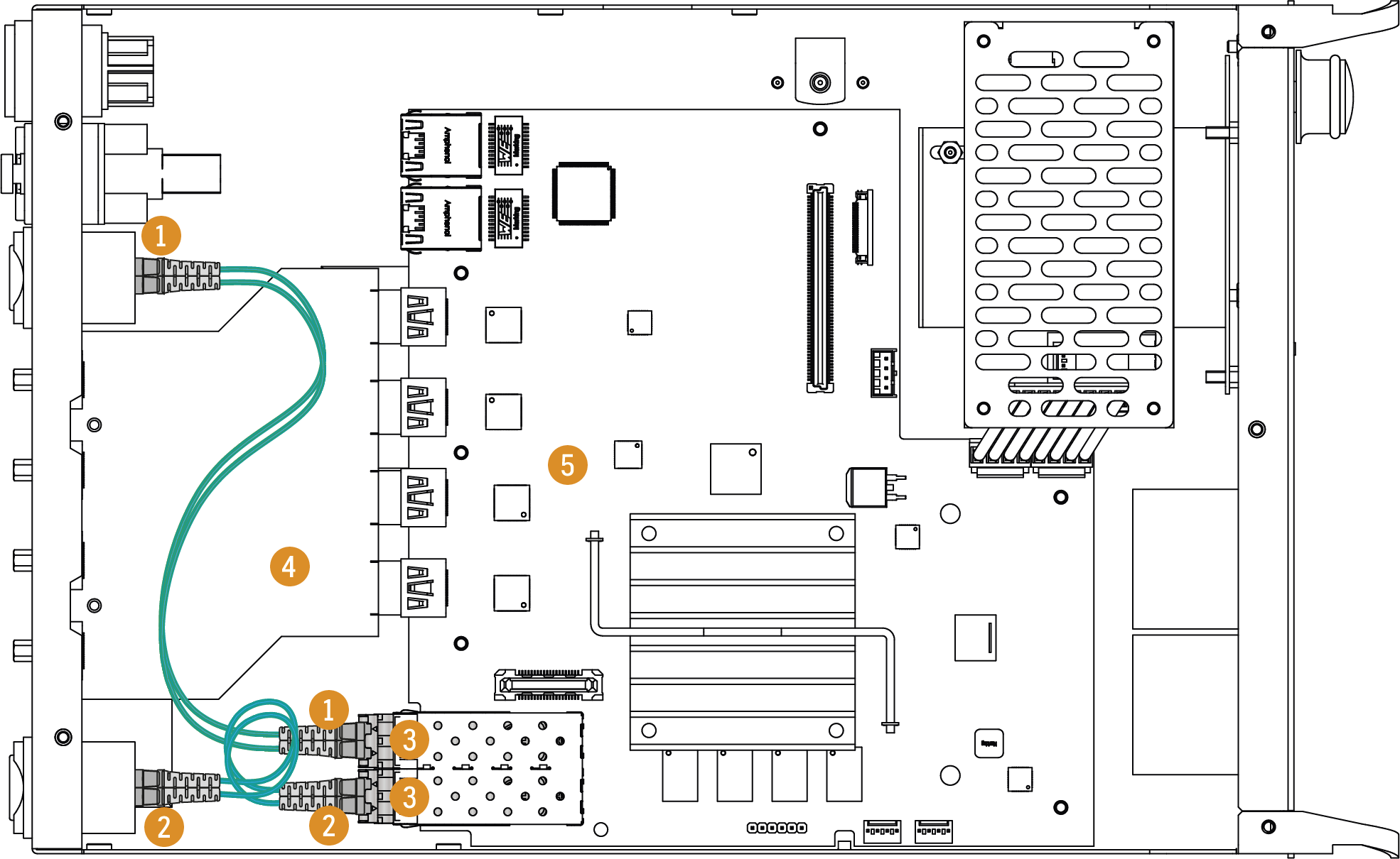
R-series endpoint device - top view in dissassembled state
Step 6.Disconnect the LC patch cable connectors 1 2 from the SFP+ modules 3.
Step 7.Pull down on the handle bar of the modules 3.
Step 8.Gently slide out the SFP+ modules 3 from the slot.
Installation of the New SFP+ Modules
ATTENTION!Always be sure of the optical mode of the new modules. 2xMM-2xDUO / 2xMM-QUAD models support multimode, 2xSM-2xDUO / 2xSM-QUAD / 2xSM-BiDi-DUO support singlemode SFP+ modules only.
Step 1.Put up on the handle bar of the new modules 3.
Step 2.Connect the modules 3 to the SFP+ port slots.
Step 3.Connect the LC patch cable connectors 1 2 to the SFP+ modules.
ATTENTION!Always be sure of the optical mode of the patch cables. Multimode SFP+ modules support multimode, singlemode SFP+ modules support singlemode optical cables only.
Step 4.Place back the top cover cautiously.
Step 5.Screw back all 15 screws to the top, left, and right side of the cover plate of the device.
WARNING!Be careful when removing and installing the patch cables and the SFP+ modules. Harming the HDMI board 4 and the motherboard 5 may cause unusable device and will void the warranty.
14.3. Air Filter Foam Changing in R-series Endpoints
The R-series endpoint devices are built with an exchangeable air filter foam in front of the fans that can be easily removed for cleaning or changing.
Affected Models
▪UBEX-PRO20-HDMI-R100 series
Removal of the Air Filter
Step 1.Disconnect the device from the power source.
WARNING!Never remove the air filter when it is connected to the power source. The cooling fans behind the foam are in operation when the device is on, touching the spinning parts may cause injury.
Step 2.Remove the air filter foam by fingers or using a forceps or clamp.
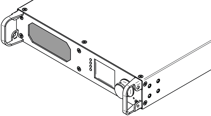
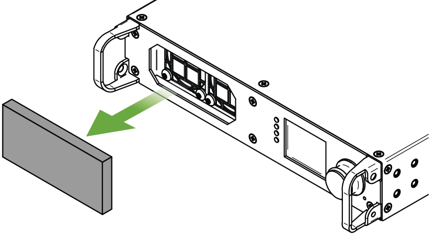
Parameters of the Foam
Size (in mm): 86W x 40H x 8D
Material: 25ppi polyurethane air filter foam
Installation of the Air Filter
Place the cleaned or new air filter foam in front of the cooling fans. Take care that all corners of the foam are inside the air filter slot.
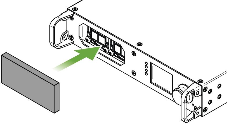
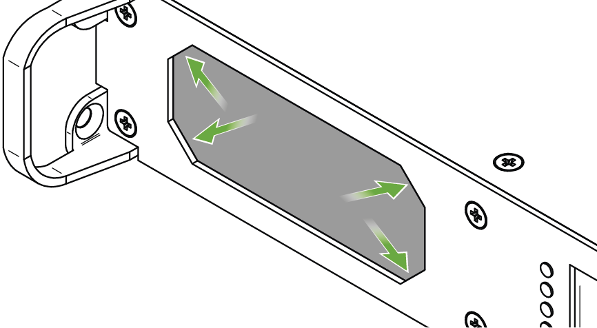
14.4. Hidden USB Connector for Debug Purpose
Affected Models
▪UBEX-PRO20-HDMI-F100, -F110, -F111, -F120, -F121, -F130
▪UBEX-PRO20-HDMI-R100 series
UBEX endpoints are built with a standard USB 2.0 mini B-type connector which is hidden under the jog dial control knob.
ATTENTION!The USB connector is for debug purpose. Please use it only if the Lightware Support requests it.
Follow the steps to reach the hidden USB connector:
Step 1.Remove the rubber ring from the jog dial knob.
Step 2.Find the screw in the side of the jog dial knob and use a hexagon (Allen) key wrench size 1.3mm to loosen it.
Step 3.Pull down the jog dial knob from the holder.
Step 4.The USB mini connector is available now.
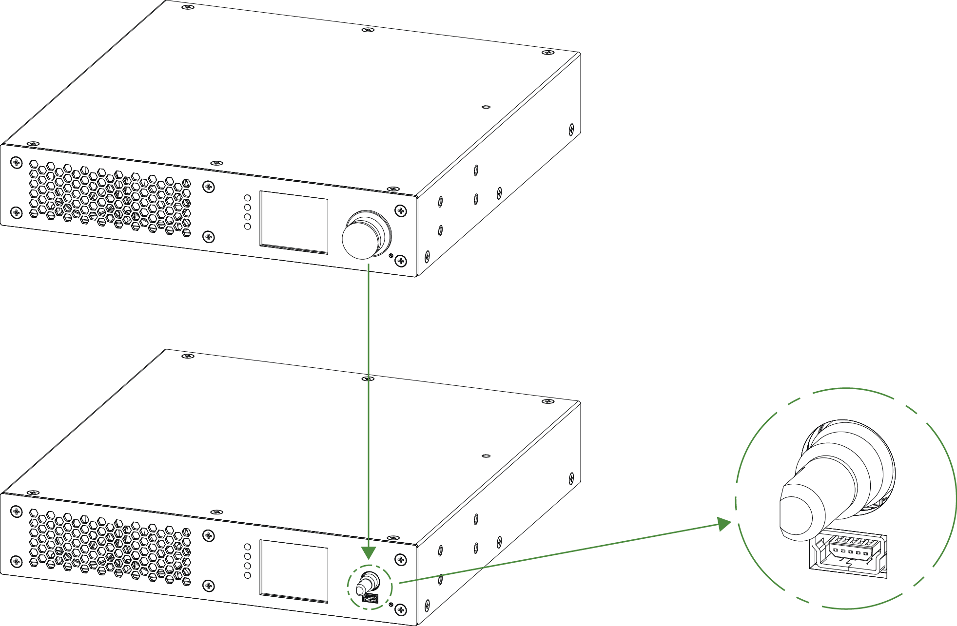
The location of the hidden USB mini connector
Tables, drawings, guides, technical details, hashtag keyword list and the Quick Link Collection as follows:
INFO:Specificatios are subject to change without notice.
15.1.1. UBEX F-series Endpoints
General
|
Compliance |
CE, UKCA |
|
EMC (emission) |
EN 55032:2015+A1:2020 |
|
EMC (immunity) |
EN 55035:2017+A11:2020 |
|
RoHS |
EN 63000:2018 |
|
Electrical safety |
EN 62368-1:2020 |
|
Laser safety |
EN 60825-1:2014+A11:2021 |
|
TEMPEST SDIP-27 Level B certification |
Available upon request |
|
Warranty |
3 years |
|
Cooling |
2x built-in fans |
|
Operating temperature |
0 to +50˚C (+32 to +122˚F) |
|
Storage temperature |
-40° to +85˚C (-40° to +185˚F) |
|
Operating humidity |
10% to 90%, non-condensing |
Power Supply
|
AC power connector |
IEC C14 receptacle |
|
Power source |
100-230 V AC, 50/60 Hz |
Power Consumption / Heat Dissipation *
|
Transmitted AV signals |
Transmitter (TX) operation mode |
Receiver (RX) operation mode |
Transceiver (TRX) operation mode |
Multiviewer (RXMV) operation mode |
|
4K60 |
21.1 W |
21.4 W |
- |
23.5 W |
|
72 BTU/h |
73 BTU/h |
- |
80.2 BTU/h |
|
|
4K30 |
20.3 W |
20.2 W |
- |
- |
|
69.3 BTU/h |
68.9 BTU/h |
- |
- |
|
|
4K30 + 4K30 |
22.9 W |
20.9 W |
21.9 W |
- |
|
78.1 BTU/h |
71.3 BTU/h |
74.7 BTU/h |
- |
|
|
4K60 + 1080p60 |
24.2 W |
21.4 W |
22.8 W |
- |
|
82.6 BTU/h |
73 BTU/h |
77.8 BTU/h |
- |
|
|
4K60 + 4K30 |
22.1 W |
21,1 W |
21.6 W |
- |
|
75.4 BTU/h |
72 BTU/h |
73.7 BTU/h |
- |
* Usage of SFP+ to RJ45 modules might increase these values with 3 W / 10.2 BTU/h approximately.
Enclosure
|
Rack mountable |
Yes, with 1U high rack shelf |
|
Material |
1 mm steel |
|
Dimensions (mm/inch) |
221W x 230D x 42.5H / 8.7W x 9D x 1.6 H |
|
Weight |
2077 g (4,57 lbs) |
Video Inputs
HDMI Input
|
Connector type |
19-pole HDMI Type A receptacle |
|
Number of ports |
2 |
|
Standard |
DVI 1.0, HDMI 2.0 |
|
Supported resolutions at 10 bits/color * |
up to 4096x2160@60Hz (4:4:4) or 4096x2160@60Hz (4:2:2) up to 3840x2160@60Hz (4:4:4) or 3840x2160@60Hz (4:2:2) |
|
Supported resolutions at 12 bits/color * |
up to 4096x2160@60Hz (4:2:0) or 3840x2160@60Hz (4:2:0) up to 4096x2160@30Hz (4:2:2) or 3840x2160@30Hz (4:2:2) 1920x1080@60Hz (4:4:4) |
|
Audio formats |
8 channel PCM Dolby Digital, Dolby Digital Plus, Dolby TrueHD, Dolby Atmos DTS, DTS-HD Master Audio 7.1, WMA Pro |
* All standard VESA, CEA and other custom resolutions up to 600MHz (HDMI 2.0) are supported.
Video Outputs
HDMI Output
|
Connector type |
19-pole HDMI Type A receptacle |
|
Number of ports |
2 |
|
Standard |
DVI 1.0, HDMI 2.0 |
|
Supported resolutions at 10 bits/color * |
up to 4096x2160@60Hz (4:4:4) or 4096x2160@60Hz (4:2:2) up to 3840x2160@60Hz (4:4:4) or 3840x2160@60Hz (4:2:2) |
|
Supported resolutions at 12 bits/color * |
up to 4096x2160@60Hz (4:2:0) or 3840x2160@60Hz (4:2:0) up to 4096x2160@30Hz (4:2:2) or 3840x2160@30Hz (4:2:2) 1920x1080@60Hz (4:4:4) |
|
Audio formats |
8 channel PCM Dolby Digital, Dolby Digital Plus, Dolby TrueHD, Dolby Atmos DTS, DTS-HD Master Audio 7.1, WMA Pro |
* All standard VESA, CEA and other custom resolutions up to 600MHz (HDMI 2.0) are supported.
SFP+ Port Slots
|
Number of ports |
2 |
|
Supported data rate |
up to 10 Gbps |
|
Accepted interfaces |
10G SFP+ optical transceiver modules DAC cables |
Audio Ports
The ports are available for the following models:
▪UBEX-PRO20-HDMI-F110
▪UBEX-PRO20-HDMI-F111
▪UBEX-PRO20-HDMI-F120
▪UBEX-PRO20-HDMI-F121
▪UBEX-PRO20-HDMI-F130
Analog Audio Input
|
Audio port connector |
5-pole Phoenix connector |
|
Audio formats |
2-channel PCM |
|
Sampling frequency |
48 kHz |
|
Maximum input level |
+0 dBu, 0.77 Vrms, 2.19 Vpp |
|
Signal transmission |
Balanced / unbalanced signal |
|
Volume |
-95 – 0 dB |
|
Balance |
-100 - +100 (0 = center) |
|
Gain |
-12 – 35 dB |
Analog Audio Output
|
Audio port connector |
5-pole Phoenix connector |
|
Audio formats |
2-channel PCM |
|
Sampling frequency |
48 kHz |
|
Volume |
-57 – 0 dB |
|
Balance |
-100 - +100 (0 = center) |
|
Nominal Differential Output Level |
+4 dBu @ 0 dB Gain |
|
Nominal Differential Output Level |
+7 dBu @ 3 dB Gain |
Control Ports
Ethernet Port
|
Number of ports - F100 |
2 |
|
Number of ports - F110 / F111 / F120 / F121 / F130 |
3 |
|
Connector type |
Locking RJ45 female |
|
Ethernet data rate |
1000Base-T, full duplex with autodetect |
|
Power over Ethernet (PoE) |
Not supported |
RS-232 Serial Port
The port is available for the following models:
▪UBEX-PRO20-HDMI-F110
▪UBEX-PRO20-HDMI-F111
▪UBEX-PRO20-HDMI-F120
▪UBEX-PRO20-HDMI-F121
▪UBEX-PRO20-HDMI-F130
|
Serial port connector |
3-pole Phoenix connector |
|
Available Baud rates |
between 4800 and 115200 |
|
Available Data bits |
8 or 9 |
|
Available Parity |
None / Odd / Even |
|
Available Stop bits |
1 / 1.5 / 2 |
Infrared Port
The port is available for the following models:
▪UBEX-PRO20-HDMI-F110
▪UBEX-PRO20-HDMI-F120
|
Input connector type |
3.5 mm TRS (approx. 1/8" jack) |
|
Output connector type |
3.5 mm TS (approx. 1/8" jack) |
|
Input carrier frequency |
38 kHz |
|
Output signal |
modulated (38kHz) / not modulated (baseband) |
USB-A Ports - F120 / F121 Models
The port is available for the following models:
▪UBEX-PRO20-HDMI-F120
▪UBEX-PRO20-HDMI-F121
|
Connector type |
USB Type-A receptacle |
|
Number of ports |
2 |
|
USB compliance |
USB 2.0 |
|
Device class |
HID |
USB-A Ports - F130 Model
The port is available for the following model:
▪UBEX-PRO20-HDMI-F130
|
Connector type |
USB Type-A receptacle |
|
Number of ports (USB-HID / USB 2.0) |
2 / 2 |
|
USB compliance |
USB 2.0 |
|
Power supplement of all USB-A ports |
5V, 1.7A (USB 2.0) / 5V, 0.3A (USB HID) |
|
Maximum current supplement per USB-A port |
1A |
USB-C Port
The port is available for the following models:
▪UBEX-PRO20-HDMI-F121
▪UBEX-PRO20-HDMI-F130
|
Connector type |
Type-C receptacle |
|
Number of ports- F121 model |
1 |
|
Number of ports - F130 model (Host / USB 2.0) |
1 / 2 |
|
USB compliance |
USB 2.0 |
USB-B Port
The port is available for the following model:
▪UBEX-PRO20-HDMI-F120
|
Connector type |
USB B-type receptacle |
|
Number of ports |
1 |
|
USB compliance |
USB 2.0 |
|
Device class |
HID |
15.1.2. UBEX R-series Endpoints
General
|
Compliance |
CE, UKCA |
|
EMC (emission) |
EN 55032:2015+A1:2020 |
|
EMC (immunity) |
EN 55035:2017+A11:2020 |
|
RoHS |
EN 63000:2018 |
|
Electrical safety |
EN 62368-1:2020 |
|
Laser safety |
EN 60825-1:2014+A11:2021 |
|
Warranty |
3 years |
|
Cooling |
2x built-in fans |
|
Operating temperature |
0 to +50˚C (+32 to +122˚F) |
|
Storage temperature |
-40° to +85˚C (-40° to +185˚F) |
|
Operating humidity |
10% to 90%, non-condensing |
Power Supply
|
AC power connector |
Neutrik powerCON TRUE1 NAC3MPX-WOT receptacle |
|
Power source |
100-230 V AC, 50/60 Hz |
Power Consumption / Heat Dissipation
|
Transmitted AV signals |
Transmitter (TX) operation mode |
Receiver (RX) operation mode |
Transceiver (TRX) operation mode |
Multiviewer (RXMV) operation mode |
|
4K60 |
21.1 W |
21.4 W |
- |
23.5 W |
|
72 BTU/h |
73 BTU/h |
- |
80.2 BTU/h |
|
|
4K30 |
20.3 W |
20.2 W |
- |
- |
|
69.3 BTU/h |
68.9 BTU/h |
- |
- |
|
|
4K30 + 4K30 |
22.9 W |
20.9 W |
21.9 W |
- |
|
78.1 BTU/h |
71.3 BTU/h |
74.7 BTU/h |
- |
|
|
4K60 + 1080p60 |
24.2 W |
21.4 W |
22.8 W |
- |
|
82.6 BTU/h |
73 BTU/h |
77.8 BTU/h |
- |
|
|
4K60 + 4K30 |
22.1 W |
21,1 W |
21.6 W |
- |
|
75.4 BTU/h |
72 BTU/h |
73.7 BTU/h |
- |
Enclosure
|
Rack mountable |
Yes |
|
Material |
1 mm steel |
|
Dimensions (mm/inch) |
221W x 364D x 42.5H / 8.7W x 14.3D x 1.6H |
|
Weight |
2077 g (4,57 lbs) |
Video Inputs
HDMI Input
|
Connector type |
19-pole HDMI Type A receptacle |
|
Number of ports |
2 |
|
Standard |
DVI 1.0, HDMI 2.0 |
|
Supported resolutions at 10 bits/color * |
up to 4096x2160@60Hz (4:4:4) or 4096x2160@60Hz (4:2:2) up to 3840x2160@60Hz (4:4:4) or 3840x2160@60Hz (4:2:2) |
|
Supported resolutions at 12 bits/color * |
up to 4096x2160@60Hz (4:2:0) or 3840x2160@60Hz (4:2:0) up to 4096x2160@30Hz (4:2:2) or 3840x2160@30Hz (4:2:2) 1920x1080@60Hz (4:4:4) |
|
Audio formats |
8 channel PCM Dolby Digital, Dolby Digital Plus, Dolby TrueHD, Dolby Atmos DTS, DTS-HD Master Audio 7.1, WMA Pro |
* All standard VESA, CEA and other custom resolutions up to 600MHz (HDMI 2.0) are supported.
Video Outputs
HDMI Output
|
Connector type |
19-pole HDMI Type A receptacle |
|
Number of ports |
2 |
|
Standard |
DVI 1.0, HDMI 2.0 |
|
Supported resolutions at 10 bits/color * |
up to 4096x2160@60Hz (4:4:4) or 4096x2160@60Hz (4:2:2) up to 3840x2160@60Hz (4:4:4) or 3840x2160@60Hz (4:2:2) |
|
Supported resolutions at 12 bits/color * |
up to 4096x2160@60Hz (4:2:0) or 3840x2160@60Hz (4:2:0) up to 4096x2160@30Hz (4:2:2) or 3840x2160@30Hz (4:2:2) 1920x1080@60Hz (4:4:4) |
|
Audio formats |
8 channel PCM Dolby Digital, Dolby Digital Plus, Dolby TrueHD, Dolby Atmos DTS, DTS-HD Master Audio 7.1, WMA Pro |
* All standard VESA, CEA and other custom resolutions up to 600MHz (HDMI 2.0) are supported.
Fiber Optical Ports
2xMM-2xDUO
|
Number of ports |
2 |
|
Connector type |
Neutrik opticalCON DUO NO2-4FDW-A |
|
SFP+ modules in the enclosure |
2x Finisar FTLX8574D3BCL |
|
Optical mode |
Multimode |
|
Wavelength |
850 nm |
2xSM-2xDUO
|
Number of ports |
2 |
|
Connector type |
Neutrik opticalCON DUO NO2-4FDW-A |
|
SFP+ modules in the enclosure |
2x Finisar FTLX1475D3BCL |
|
Optical mode |
Singlemode |
|
Wavelength |
1310 nm |
2xMM-QUAD
|
Number of ports |
1 |
|
Connector type |
Neutrik opticalCON QUAD NO4FDW-A |
|
SFP+ modules in the enclosure |
2x Finisar FTLX8574D3BCL |
|
Optical mode |
Multimode |
|
Wavelength |
850 nm |
2xSM-QUAD
|
Number of ports |
1 |
|
Connector type |
Neutrik opticalCON QUAD NO4FDW-A |
|
SFP+ modules in the enclosure |
2x Finisar FTLX1475D3BCL |
|
Optical mode |
Singlemode |
|
Wavelength |
1310 nm |
2xSM-BiDi-DUO
|
Number of ports |
1 |
|
Connector type |
Neutrik opticalCON DUO NO2-4FDW-A |
|
SFP+ modules in the enclosure |
1x Finisar FTLX2072D327 1x Finisar FTLX2072D333 |
|
Optical mode |
Singlemode |
|
Wavelengths |
1271 nm, 1331 nm |
Control Ports
Ethernet Port
|
Connector type |
Neutrik etherCON NE8FDV-YK |
|
Number of ports - 2xMM-2xDUO / 2xSM-2xDUO |
1 |
|
Number of ports - 2xMM-QUAD / 2xSM-QUAD / 2xSM-BiDi-DUO |
2 |
|
Ethernet data rate |
1000Base-T, full duplex with autodetect |
|
Power over Ethernet (PoE) |
Not supported |
15.1.3. UBEX-MMU-X200
General
|
Compliance |
CE, UKCA |
|
EMC (emission) |
EN 55032:2015+A1:2020 |
|
EMC (immunity) |
EN 55035:2017+A11:2020 |
|
RoHS |
EN 63000:2018 |
|
Electrical safety |
EN 62368-1:2020 |
|
Laser safety |
EN 60825-1:2014+A11:2021 |
|
Warranty |
3 years |
|
Cooling |
passive |
|
Operating temperature |
0 to +50˚C (+32 to +122˚F) |
|
Storage temperature |
-40° to +85˚C (-40° to +185˚F) |
|
Operating humidity |
10% to 90%, non-condensing |
Power
|
AC power connector |
IEC C14 receptacle |
|
Power source |
IEC 100-230 V AC, 50/60 Hz |
|
Power consumption |
3 W |
|
Heat dissipation |
10,2 BTU/h |
Enclosure
|
Rack mountable |
Yes |
|
Material |
1 mm steel |
|
Dimensions in mm |
482W x 150D x 43.9H |
|
Dimensions in inch |
18.9W x 5.9D x 1.7 H |
|
Weight |
1897 g (4,18 lbs) |
Control Ports for UBEX Network
SFP Port Slot
|
Supported data rate |
up to 1 Gbps |
|
Accepted interfaces |
SFP optical transceiver module |
|
DAC cable |
Ethernet Port
|
Connector type |
Locking RJ45 female |
|
Ethernet data rate |
1000Base-T, full duplex with autodetect |
|
Power over Ethernet (PoE) |
Not supported |
Control Ethernet Ports
Control Ethernet 1
|
Connector type |
Locking RJ45 female |
|
Location |
Front panel |
|
Ethernet data rate |
100Base-T, auto-negotiation, auto-MDI/MDIX |
|
Power over Ethernet (PoE) |
Not supported |
Control Ethernet 2
|
Connector type |
Locking RJ45 female |
|
Location |
Rear panel |
|
Ethernet data rate |
1000Base-T, auto-negotiation, auto-MDI/MDIX |
|
Power over Ethernet (PoE) |
Not supported |
USB Control Port
|
USB connector |
USB mini B type |
|
USB 2.0 compliance |
Yes |
RS-232 Control Ports
|
Number of ports |
2 |
|
Connector type |
3-pole Phoenix connector |
|
Available Baud rates |
between 4800 and 115200 |
|
Available Data bits |
8 or 9 |
|
Available Parity |
None / Odd / Even |
|
Available Stop bits |
1 / 1.5 / 2 |
15.2. Factory Default Settings
15.2.1. UBEX-PRO20-HDMI-F100 / R100 series
|
Parameter |
Setting/Value |
|---|---|
|
General settings |
|
|
Device label (F100) |
UBEX-PRO20-HDMI-F100 |
|
Device label (R100 series) |
UBEX-PRO20-HDMI-R100 <variant> |
|
Operation mode |
Keeps the current operation mode |
|
Display backlight |
10 |
|
Jog dial rotary direction |
Clockwise (CW down) |
|
Video input port settings (TX - HDMI in 1 and 2 / TRX - HDMI in 2) |
|
|
HDCP authentication |
Enabled |
|
Stream enable |
Enabled |
|
Emulated EDID on the inputs |
Dynamic |
|
Video output port settings (RX - HDMI out 1 and 2 / TRX - HDMI out 1 / RXMV - HDMI out 1 and 2) |
|
|
HDCP mode |
Depends on input (Auto) |
|
Power 5V mode |
Always on |
|
Timing mode |
Free run |
|
No sync screen mode |
Always off |
|
No sync screen color |
R: 128, G: 128, B: 128 (grey) |
|
Local video input port settings (RX - HDMI in 1 and 2 / RXMV - HDMI in 1 and 2) |
|
|
HDCP authentication |
Enabled |
|
Emulated EDID on the inputs |
Dynamic |
|
Local video output port settings (TX - HDMI out 1 and 2 / TRX - HDMI out 2) |
|
|
HDCP mode |
Auto |
|
Power 5V mode |
Always on |
|
No sync screen mode |
Always off |
|
No sync screen color |
R: 128, G: 128, B: 128 (grey) |
|
Source MUX settings |
|
|
RX - HDMI out 1 |
Stream (D1) |
|
RX - HDMI out 2 |
Stream (D2) |
|
TRX - HDMI out 2 |
HDMI in 2 (I2) |
|
Scaler settings (TX - HDMI in 1 and 2 / RX - HDMI out 1 and 2 / RXMV - HDMI out 2 / TRX - HDMI in 2 and HDMI out 1) |
|
|
Scaler enable |
Disabled (Passthrough mode) |
|
Scale to |
1920x1080p60 |
|
Image position |
Fit |
|
Color space conversion (CSC) |
No conversion |
|
Color range |
No conversion |
|
Color depth |
Passthrough |
|
Multiviewer settings (RXMV - HDMI out 1) |
|
|
Canvas resolution |
3840x2160p60 |
|
Color depth |
8 bpc |
|
Tile layer order |
1;2;3;4 |
|
Tile enabled |
True |
|
Tile positions (T1 / T2 / T3 / T4) |
0,0 / 1920,0 / 0,1080 / 1920,1080 |
|
Tile size |
1920x1080 |
|
Tile opacity |
100% |
|
Network settings |
|
|
Static IP address - TX / TRX mode |
192.168.0.101 |
|
Static IP address - RX / RXMV mode |
192.168.0.102 |
|
DHCP (dynamic IP address) |
Disabled |
|
Subnet mask |
255.255.255.0 |
|
Static gateway |
192.168.0.1 |
|
LW3 port number |
6107 |
|
HTTP port number |
80 |
|
Miscellaneous |
|
|
Application mode |
Auto |
|
Dark mode |
Disabled |
|
Control lock |
Disabled |
|
Unique port names |
Cleared |
|
Unique device label |
Cleared |
|
User EDIDs |
Not cleared |
15.2.2. UBEX-PRO20-HDMI-F110 / F111
|
Parameter |
Setting/Value |
|---|---|
|
General settings |
|
|
Device label |
UBEX-PRO20-HDMI-F110 |
|
Operation mode |
Keeps the current operation mode |
|
Display backlight |
10 |
|
Jog dial rotary direction |
Clockwise (CW down) |
|
Video input port settings (TX - HDMI in 1 and 2 / TRX - HDMI in 2) |
|
|
HDCP authentication |
Enabled |
|
Stream enable |
Enabled |
|
Emulated EDID on the inputs |
Dynamic |
|
Video output port settings (RX - HDMI out 1 and 2 / RXMV - HDMI out 1 and 2 / TRX - HDMI out 1) |
|
|
HDCP mode |
Depends on input (Auto) |
|
Power 5V mode |
Always on |
|
Timing mode |
Free run |
|
No sync screen mode |
Always off |
|
No sync screen color |
R: 128, G: 128, B: 128 (grey) |
|
Local video input port settings (RX - HDMI in 1 and 2 / RXMV - HDMI in 1 and 2) |
|
|
HDCP authentication |
Enabled |
|
Emulated EDID on the inputs |
Dynamic |
|
Local video output port settings (TX - HDMI out 1 and 2 / TRX - HDMI out 2) |
|
|
HDCP mode |
Auto |
|
Power 5V mode |
Always on |
|
No sync screen mode |
Always off |
|
No sync screen color |
R: 128, G: 128, B: 128 (grey) |
|
Color depth |
Passthrough |
|
Source MUX settings |
|
|
RX - HDMI out 1 |
Stream (D1) |
|
RX - HDMI out 2 |
Stream (D2) |
|
TRX - HDMI out 2 |
HDMI in 2 (I2) |
|
Scaler settings (TX - HDMI in 1 and 2 / RX - HDMI out 1 and 2 / RXMV - HDMI out 2 / TRX - HDMI in 2 and HDMI out 1) |
|
|
Scaler enable |
Disabled (Pass-through mode) |
|
Scale to |
1920x1080p60 |
|
Image position |
Fit |
|
Color space conversion (CSC) |
No conversion |
|
Color depth |
Passthrough |
|
Multiviewer settings (RXMV - HDMI out 1) |
|
|
Canvas resolution |
3840x2160p60 |
|
Color depth |
8 bpc |
|
Tile layer order |
1;2;3;4 |
|
Tile enabled |
True |
|
Tile positions (T1 / T2 / T3 / T4) |
0,0 / 1920,0 / 0,1080 / 1920,1080 |
|
Tile size |
1920x1080 |
|
Tile opacity |
100% |
|
Analog audio input port properties |
|
|
Volume |
0.00 dB (100%) |
|
Balance |
0 (center) |
|
Gain |
0.00 dB |
|
Analog audio output port properties |
|
|
Volume |
0.00 dB (100%) |
|
Balance |
0 (center) |
|
Network settings |
|
|
Static IP address - TX/TRX mode |
192.168.0.101 |
|
Static IP address - RX/RXMV mode |
192.168.0.102 |
|
DHCP (dynamic IP address) |
Disabled |
|
Subnet mask |
255.255.255.0 |
|
Static gateway |
192.168.0.1 |
|
LW3 port number |
6107 |
|
HTTP port number |
80 |
|
RS-232 port settings |
|
|
Operation mode |
Command injection |
|
TCP port |
8001 |
|
Configuration |
57600 BAUD 8N1 |
|
Miscellaneous |
|
|
Application mode |
Auto |
|
Dark mode |
Disabled |
|
Control lock |
Disabled |
|
Unique port names |
Cleared |
|
Unique device label |
Cleared |
|
User EDIDs |
Not cleared |
15.2.3. UBEX-PRO20-HDMI-F120 / F121
|
Parameter |
Setting/Value |
|---|---|
|
General settings |
|
|
Device label |
UBEX-PRO20-HDMI-F120 |
|
Operation mode |
Keeps the current operation mode |
|
Display backlight |
10 |
|
Jog dial rotary direction |
Clockwise (CW down) |
|
Video input port settings (TX - HDMI in 1 and 2 / TRX - HDMI in 2) |
|
|
HDCP authentication |
Enabled |
|
Stream enable |
Enabled |
|
Emulated EDID on the inputs |
Dynamic |
|
Video output port settings (RX - HDMI out 1 and 2 / RXMV - HDMI out 1 and 2 / TRX - HDMI out 1) |
|
|
HDCP mode |
Depends on input (Auto) |
|
Power 5V mode |
Always on |
|
Timing mode |
Free run |
|
No sync screen mode |
Always off |
|
No sync screen color |
R: 128, G: 128, B: 128 (grey) |
|
Local video input port settings (RX - HDMI in 1 and 2 / RXMV - HDMI in 1 and 2) |
|
|
HDCP authentication |
Enabled |
|
Emulated EDID on the inputs |
Dynamic |
|
Local video output port settings (TX - HDMI out 1 and 2 / TRX - HDMI out 2) |
|
|
HDCP mode |
Auto |
|
Power 5V mode |
Always on |
|
No sync screen mode |
Always off |
|
No sync screen color |
R: 128, G: 128, B: 128 (grey) |
|
Scaler settings (TX - HDMI in 1 and 2 / RX - HDMI out 1 and 2 / RXMV - HDMI out 2 / TRX - HDMI in 2 and HDMI out 1) |
|
|
Scaler enable |
Disabled (Pass-through mode) |
|
Scale to |
1920x1080p60 |
|
Image position |
Fit |
|
Color space conversion (CSC) |
No conversion |
|
Color depth |
Passthrough |
|
Color depth |
Passthrough |
|
Source MUX settings |
|
|
RX - HDMI out 1 |
Stream (D1) |
|
RX - HDMI out 2 |
Stream (D2) |
|
TRX - HDMI out 2 |
HDMI in 2 (I2) |
|
Multiviewer settings (RXMV - HDMI out 1) |
|
|
Canvas resolution |
3840x2160p60 |
|
Color depth |
8 bpc |
|
Tile layer order |
1;2;3;4 |
|
Tile enabled |
True |
|
Tile positions (T1 / T2 / T3 / T4) |
0,0 / 1920,0 / 0,1080 / 1920,1080 |
|
Tile size |
1920x1080 |
|
Tile opacity |
100% |
|
Analog audio input port properties |
|
|
Volume |
0.00 dB (100%) |
|
Balance |
0 (center) |
|
Gain |
0.00 dB |
|
Analog audio output port properties |
|
|
Volume |
0.00 dB (100%) |
|
Balance |
0 (center) |
|
Network settings |
|
|
Static IP address - TX mode |
192.168.0.101 |
|
Static IP address - RX mode |
192.168.0.102 |
|
Static IP address - TRX mode |
192.168.0.101 |
|
DHCP (dynamic IP address) |
Disabled |
|
Subnet mask |
255.255.255.0 |
|
Static gateway |
192.168.0.1 |
|
LW3 port number |
6107 |
|
HTTP port number |
80 |
|
RS-232 port settings |
|
|
Operation mode |
Command injection |
|
TCP port |
8001 |
|
Configuration |
57600 BAUD 8N1 |
|
USB K+M |
|
|
Remote/Local control mode |
Remote |
|
Miscellaneous |
|
|
Application mode |
Auto |
|
Dark mode |
Disabled |
|
Control lock |
Disabled |
|
Unique port names |
Cleared |
|
Unique device label |
Cleared |
|
User EDIDs |
Not cleared |
15.2.4. UBEX-PRO20-HDMI-F130
|
Parameter |
Setting/Value |
|---|---|
|
General settings |
|
|
Device label |
UBEX-PRO20-HDMI-F130 |
|
Operation mode |
Keeps the current operation mode |
|
Display backlight |
10 |
|
Jog dial rotary direction |
Clockwise (CW down) |
|
Video input port settings (TX - HDMI in 1 and 2 / TRX - HDMI in 2) |
|
|
HDCP authentication |
Enabled |
|
Stream enable |
Enabled |
|
Emulated EDID on the inputs |
Dynamic |
|
Video output port settings (RX - HDMI out 1 and 2 / RXMV - HDMI out 1 and 2 / TRX - HDMI out 1) |
|
|
HDCP mode |
Depends on input (Auto) |
|
Power 5V mode |
Always on |
|
Timing mode |
Free run |
|
No sync screen mode |
Always off |
|
No sync screen color |
R: 128, G: 128, B: 128 (grey) |
|
Local video input port settings (RX - HDMI in 1 and 2 / RXMV - HDMI in 1 and 2) |
|
|
HDCP authentication |
Enabled |
|
Emulated EDID on the inputs |
Dynamic |
|
Local video output port settings (TX - HDMI out 1 and 2 / TRX - HDMI out 2) |
|
|
HDCP mode |
Auto |
|
Power 5V mode |
Always on |
|
No sync screen mode |
Always off |
|
No sync screen color |
R: 128, G: 128, B: 128 (grey) |
|
Scaler settings (TX - HDMI in 1 and 2 / RX - HDMI out 1 and 2 / RXMV - HDMI out 2 / TRX - HDMI in 2 and HDMI out 1) |
|
|
Scaler enable |
Disabled (Pass-through mode) |
|
Scale to |
1920x1080p60 |
|
Image position |
Fit |
|
Color space conversion (CSC) |
No conversion |
|
Color depth |
Passthrough |
|
Color depth |
Passthrough |
|
Source MUX settings |
|
|
RX - HDMI out 1 |
Stream (D1) |
|
RX - HDMI out 2 |
Stream (D2) |
|
TRX - HDMI out 2 |
HDMI in 2 (I2) |
|
Multiviewer settings (RXMV - HDMI out 1) |
|
|
Canvas resolution |
3840x2160p60 |
|
Color depth |
8 bpc |
|
Tile layer order |
1;2;3;4 |
|
Tile enabled |
True |
|
Tile positions (T1 / T2 / T3 / T4) |
0,0 / 1920,0 / 0,1080 / 1920,1080 |
|
Tile size |
1920x1080 |
|
Tile opacity |
100% |
|
Analog audio input port properties |
|
|
Volume |
0.00 dB (100%) |
|
Balance |
0 (center) |
|
Gain |
0.00 dB |
|
Analog audio output port properties |
|
|
Volume |
0.00 dB (100%) |
|
Balance |
0 (center) |
|
Network settings |
|
|
Static IP address - TX mode |
192.168.0.101 |
|
Static IP address - RX mode |
192.168.0.102 |
|
Static IP address - TRX mode |
192.168.0.101 |
|
DHCP (dynamic IP address) |
Disabled |
|
Subnet mask |
255.255.255.0 |
|
Static gateway |
192.168.0.1 |
|
LW3 port number |
6107 |
|
HTTP port number |
80 |
|
RS-232 port settings |
|
|
Operation mode |
Command injection |
|
TCP port |
8001 |
|
Configuration |
57600 BAUD 8N1 |
|
USB KVM |
|
|
Remote/Local USB HID control mode |
Remote |
|
Remote (REX) / Local (LEX) operation mode |
Remote |
|
Miscellaneous |
|
|
Application mode |
Auto |
|
Dark mode |
Disabled |
|
Control lock |
Disabled |
|
Unique port names |
Cleared |
|
Unique device label |
Cleared |
|
User EDIDs |
Not cleared |
|
Parameter |
Setting/Value |
|---|---|
|
Network settings |
|
|
IP address |
192.168.0.100 |
|
Subnet mask |
255.255.255.0 |
|
Static gateway |
192.168.0.1 |
|
DHCP |
Disabled |
|
LW3 port number |
6107 |
|
RS-232 port configuration |
|
|
Configuration |
BAUD 115200 8N1 |
|
UBEX matrix |
|
|
UBEX matrix database, including: ▪Database of claimed endpoints; ▪Crosspoint settings; ▪Stream names; ▪Device names; ▪Tags; ▪Port properties; ▪Scaler / FRC / CSC / Color range settings; ▪Video wall configuration; ▪Multiviewer configuration. |
Cleared |
|
Endpoint license |
Not cleared |
The backup file contains numerous settings and parameters saved from the device. When the file is uploaded to a device, the following will be overwritten.
INFO:The configuration settings of the endpoint devices are stored in the MMU in Matrix application mode.
For the procedure of the backup and restore function, see the details in the System Tab section.
|
General |
|
Device label |
|
NTP mode, NTP server address |
|
Endpoint management settings |
|
List of the claimed endpoints |
|
Operation mode of the endpoints |
|
Device assignments |
|
Crosspoint settings |
|
Video stream connection states, Audio stream connection states |
|
Source MUX settings |
|
USB K+M connection states |
|
Stream source settings |
|
Stream names, Tags, Icons |
|
HDCP setting |
|
Scaler enable/disable status, Resolution setting, Image position |
|
Frame rate converter enable/disable status, Resolution setting |
|
Color space conversion setting, color depth setting |
|
Destination port settings |
|
Stream names, Tags, Icons |
|
HDCP mode, Power +5V mode, Color depth setting |
|
Scaler enable/disable status, Resolution setting, Image position |
|
Frame rate converter enable/disable status, Resolution setting |
|
Color space conversion setting; Color range setting, Color depth setting |
|
No sync screen mode, No sync screen color |
|
Video wall settings |
|
All video wall related settings |
|
Multiviewer settings |
|
All multiviewer related settings |
|
EDID management settings |
|
User EDID data, Emulated EDIDs by ports, Dynamic EDID data |
|
Ethernet port settings |
|
MMU control ports: Name, Mode |
|
Endpoint control ports: Name, Mode |
|
Serial port configuration |
|
MMU: Baudrate, Databits, Stopbits, Parity |
|
Endpoints: Baudrate, Stopbits, Parity, Port name |
15.4. Control Port Numbering of the MMU
|
Description |
Port number |
|
|
Serial control ports |
RS-232 1 |
P1 |
|
RS-232 2 |
P2 |
|
15.5. Endpoint Port Numbering (Stream ID Calculation)
All endpoint devices which are connected to the UBEX matrix got a logical device ID generated by the MMU.
DEFINITION:Logical device ID means the MMU assigns a number to the endpoints ordered by the discovery.
The stream ID is based on the logical device ID. The registered endpoint can be transmitter, receiver, or transceiver. All transmitters have two inputs, all receivers have two outputs, and all transceivers have one input and one output. In case of the transmitter, the user can select between two streams per HDMI input port fro the transmission: a processed (scaled) stream (S101 / S102) or a native (deep color) one (S103 / S104). The first discovered endpoint gets the X1 logical device ID, the HDMI port 1 of the endpoint is always the 01 number, the HDMI port 2 is always the 02 number. If the endpoint has input port (TX / TRX), it is signed with S as Source, if it has output port (RX / TRX), it is signed with D as Destination. The formula of the stream ID is the following:
<Port_type><Logical_device_ID><Port_number>
Two endpoint devices cannot be assigned to the same logical device ID. The number is always calculated for the endpoints independently from the operation mode.
INFO:The logical device ID (and the order of the endpoints) can be changed by the LDC software (see the details in the Device Map section) or by LW3 protocol command (see the details in the Assigning an Endpoint to a Logical Device ID section).
Example
The following table helps to clear up the calculation of the stream ID:
|
Operation mode |
Port number |
Stream ID |
Description |
Discovery order |
|
|
TX (Transmitter) |
HDMI in 1 |
S101 |
Processed stream |
1. |
|
|
S103 |
Native stream |
||||
|
HDMI in 2 |
S102 |
Processed stream |
|||
|
S104 |
Native stream |
||||
|
RX (Receiver) |
HDMI out 1 |
D201 |
Processed stream |
2. |
|
|
HDMI out 2 |
D202 |
Processed stream |
|||
|
TRX (Transceiver) |
HDMI in 2 |
S302 |
Processed stream |
3. |
|
|
HDMI out 1 |
D301 |
Processed stream |
|||
|
RXMV (Multiviewer) |
HDMI out 1 |
D401 |
Multiview streams |
Tile 1 |
4. |
|
D402 |
Tile 2 |
||||
|
D403 |
Tile 3 |
||||
|
D404 |
Tile 4 |
||||
|
HDMI out 2 |
D405 |
Processed stream |
|||
Examples and explanations for stream IDs
15.6. Applied Ports (Network Settings)
The following ports are necessary to pass via a network switch/firewall for a proper working between the device and the softwares:
|
Purpose/function |
Affected software |
Protocol |
Port nr. |
|
Firmware update TFTP |
LDU2 |
UDP |
69 |
|
UDP |
50000 |
||
|
Device Discovery |
LDC |
UDP |
224.0.0.251:5353 |
|
Remote IP |
LDC |
UDP |
230.76.87.82:37421 |
|
LW3 protocol |
- |
TCP |
6107 |
|
HTTP port |
- |
TCP |
80 |
|
RS-232 command injection |
- |
TCP |
8001, 8002 |
|
IR command injection |
- |
TCP |
9001, 9002, 9003, 9004 |
|
USB 2.0 discovery (F130 model only) |
- |
UDP |
6137, 6971 |
|
USB KVM connection between the F130 endpoints |
- |
UDP |
6973 |
15.7. Release Notes of the Firmware Packages
15.7.1. Endpoint Series
Valid for the following models:
▪UBEX-PRO20-HDMI-F100
▪UBEX-PRO20-HDMI-F110
▪UBEX-PRO20-HDMI-F111
▪UBEX-PRO20-HDMI-F120
▪UBEX-PRO20-HDMI-F121
▪UBEX-PRO20-HDMI-F130
▪UBEX-PRO20-HDMI-R100 series
v3.5.5b8
Release date: 2026-02-09
New feature:
▪The new firmware introduces enhanced protection mechanisms to detect faults in certain protocol converter cables (DP/miniDP/USB-C to HDMI) and safeguard the UBEX from their potential effects. For optimal performance, we recommend using Lightware-manufactured USB-C to HDMI cables, as the device has been validated to operate reliably with them. When third-party cables are used, certain video input changes\u2014such as resolution or audio sampling rate adjustments\u2014may cause the cable\u2019s audio transmission to fail, resulting in distorted sound and significant fluctuations in CTS/N values. To mitigate these issues, the firmware automatically mutes the embedded audio upon fault detection to protect the UBEX. In addition, two independent optional controls are available via the LW3 API. One setting enables the device to issue an automatic HPD signal to attempt recovery of the cable from the faulty state (enabled by default). A separate setting allows the UBEX endpoint to automatically reboot if it becomes unreachable on the network due to such an error (disabled by default). These features can be used independently or together, depending on system requirements. For further assistance, please contact Support.
v3.5.3b1
Release date: 2025-02-20
New feature:
▪Alternative hardware component (LCD display) support with driver update
v3.5.2b1
Release date: 2025-01-21
New feature:
▪A clock tick-overflow issue has been fixed, which previously required a workaround that caused the product to restart every 49 days. The product is now back to full 24/7 operation.
v3.5.1b1
Release date: 2024-10-01
New feature:
▪Fix the update script in the last package.
v3.5.0b4
Release date: 2024-08-26
New feature:
▪Support F111 and F121 variants.
v3.4.0b7
Release date: 2024-06-17
New feature:
▪The new firmware supports the new F130 hardware and USB 2.0 extension. Known limitations: - missing LDC support for multiview mode and multistream in transmitter mode - USB 2.0 connection requires LARA or an external controller; USB 2.0 switching is not yet supported by the LW3 API
v3.3.1b1
Release date: 2023-10-06
Bugfix:
▪Fixed the numbers of supported streams in Multiviewer mode
v3.3.0b4
Release date: 2023-09-11
New feature:
▪Multistream is supported in transmitter mode. It could transmit 4 streams instead of 2 streams. Both HDMI input can be transmitted as scaled and native mode in same time.
v3.2.0b9
Release date: 2023-08-30
New feature:
▪A new operating mode (multiview) has been added to the endpoint firmware without MMU and LDC support for now. Currently it can be only configured by LW3 commands according to the user manual.
▪Added new scaling options ("Tile resolution") in TX and TRX mode for proper multiview operation.
v3.1.3b1
Release date: 2023-10-26
Bugfix:
▪Fixed the Link led issue
v3.1.2b1
Release date: 2023-10-04
Bugfix:
▪Fixed an audio issue with some sources, improved the robustness of the product
v3.1.1b3
Release date: 2023-07-19
New feature:
▪Forced output color depth option is added for the perfect seamless switching. UBEX supports limiting the color depth also on the link to reduce the bandwidth.
▪The UBEX endpoint supports deep color and HDR contents (e.g. Dolby Vision). The new version (v3.1.1) isn't compatible with previous versions (v2.x.y).
v3.0.2b3
Release date: 2023-07-19
New feature:
▪The minimum speed of the fans has been set to 2500 RPM.
▪Firmware update is improved and flash memory is extended. The functionality is the same as v2.4.1. It is a compatibility package because of the downgrading from v3.x.y to v2.x.y is not possible.
v3.0.0b2
Release date: 2023-03-16
New feature:
▪The UBEX endpoint supports deep color and HDR contents (e.g. Dolby Vision). The new version (v3.0.0) isn't compatible with previous versions (v2.x.y).
v2.4.1b13
Release date: 2022-09-13
New feature:
▪We fixed some known issue in the firmware of the portprocessor, like random black screen on the output after rebooting.
▪Added the scaler function for the second video pipe in transmitter mode.
Bugfix:
▪We fixed the random initialization issue of video pipe at some resolutions (e.g. 2912x2184p60).
v2.3.3b10
Release date: 2022-07-25
New feature:
▪Incompatibility issue with newer version of AVI info frame is fixed. AVI info frame version 4 is converted to version 2.
v2.3.2b4
Release date: 2022-06-16
New feature:
▪Fixed the RJ45 converter module test issue of the EOLT (production).
Bugfix:
▪Some resolutions (e.g. 2080x2184p60) didn't work properly, so we improved our bandwidth calculation algorithm and fixed this issue.
v2.3.1b1
Release date: 2022-02-11
Bugfix:
▪Fixed an End-of-Line Test (EOLT) reboot issue.
v2.3.0b1
Release date: 2022-02-09
New feature:
▪USB KM (HID devices such as keyboard, mouse) extension added to the firmware. Only the F120 hardware version and currently only the emulated transmission mode are supported.
▪Support for the "SFP+ to RJ45" converter module has been added to the firmware. In this case, the minimum fan speed is 2500 rpm.
v2.1.0b3
Release date: 2021-09-01
New feature:
▪The scaling module was also added to the second video pipe in receiver mode. Both outputs of UBEX receivers are scalable.
▪The scaling module was also added to the input video pipe in transceiver mode. Both input and output of UBEX transceivers are scalable.
v2.0.0b6
Release date: 2021-06-18
New feature:
▪Added HBR audio support
▪Replaced HDMI IP core and driver
▪Fixed sync polarity handling
Bugfix:
▪Fixed glitches with Channel Status display in audio nodes
▪Fixed frame detector values for 4:2:0 signals
▪Fixed reliability issues with audio signal type detection and pass-through
▪Fixed LW3 error with SFP Compatible property when not seated
v1.5.5b3
Release date: 2020-12-17
Bugfix:
▪Fixed 4:2:2 10-bit video transmission
▪Fixed issues with 2.1 or more audio channels
v1.5.4b1
Release date: 2020-10-07
Bugfix:
▪Fixed the video timing and audio bug.
v1.5.3b1
Release date: 2020-09-10
New feature:
▪Added 3840x2400p60_reduced timing to scaler
Bugfix:
▪Fixed a glitch with static IP settings storage
▪Fixed the inconsistency of factory default network settings on RX devices
▪Fixed a regression in EOL testing
v1.5.2b1
Release date: 2020-08-12
Bugfix:
▪Fixed a compatibility issue with older LDU2 releases
▪Fixed reliability problems with the HTTP server component
▪Fixed an issue with pre-v1.4.0 migration support
▪Fixed flash storage support that caused boot loops on some devices
v1.5.1b1
Release date: 2020-05-26
Bugfix:
▪Fixed a bug with IR reception
v1.5.0b8
Release date: 2020-05-11
New feature:
▪Source locked mode is now supported.
▪Scaling and frame rate conversion are also supported on transmitter side.
▪The frame rate converter and scaler modules support image cropping in case of downscaling in center image position.
▪12-bit deep color HDMI signals can be transmitted in 10 bit mode.
▪Extended Identify Me feature to RJ45 ports
▪Added support for cropper on secodary video pipe
▪Added Compatible property to SFP nodes
▪Added home screen to LCD menu
▪Added local input loopback and copy features to RX mode
▪Added support for automatic video freeze on signal loss as a NoSync option
▪Added copy feature to TRX mode
▪Added support for manual video freeze
▪Added support for Dark Mode
▪Updated video processing latency calculations (fixes tearing and flickering issues in some setups)
▪Added processing latency property to video pipes
▪Added support for altering Color Range
▪Added overall Health Status properties
Bugfix:
▪SCDC registers are only modified, if the connected display supports this protocol.
▪4k60 resolution was not transmitted to displays, which were 4k60 capable, but did not report SCDC capability in EDID, such as LG27UD58. Fixed.
▪Fixed video tearing when converting between 60 and 24 Hz
▪Fixed a glitch with EDID caching
▪Fixed a glitch with HDMI outputs after operation mode change (TX/RX/TRX)
▪Fixed a glitch with TMDS clocks between 310 and 340 MHz (e.g. 3440x1440p60)
▪Fixed artifacts with video wall at 4K60
▪Fixed HDMI audio node 'Connected' state
▪Improved support for newer SFP+ standards (OM3/OM4 and copper lengths)
▪Fixed a glitch that could cause an additional delay of one frame
v1.4.2b4
Release date: 2020-01-30
New feature:
▪Added option to force HDCP 2.2 Type 1 Content on outputs
Bugfix:
▪Fixed glitches with settings storage and factory defaults restoration
▪Improved support for updating devices that are already in service mode
v1.4.1b2
Release date: 2019-12-03
Bugfix:
▪Fixed a glitch with input scaler configuration storage
▪Optimized runtime memory usage
v1.4.0b4
Release date: 2019-11-27
New feature:
▪Added check to refuse downgrading to earlier versions
Bugfix:
▪Added file system in order to cope with bad NAND flash blocks
▪Improved stability for multicast update
v1.3.2b2
Release date: 2019-08-14
New feature:
▪Fixed issues with using the 10.0.0.0/8 IP range for control
v1.3.1b5
Release date: 2019-07-02
New feature:
▪Added support for No Sync Screen generation on TX/TRX sources (for network diagnostics)
▪Added support for LDC Orientation Preference setting
▪Improved LLDP support (reporting operation mode and package version)
▪Added identify() method to S and O nodes
▪Fixed channel status data for analog audio inputs
▪Refined fan control (silent operation)
▪Added support for R100 part numbers
▪Added support for IR in F110
▪Added support for centralized firmware update
Bugfix:
▪Fixed a glitch with some 10G switches not switching streams automatically
Known issue:
▪Video output is unstable when scaling a pre-cropped image to 4K@60
v1.3.0b10
Release date: 2019-05-03
New feature:
▪Added support for Transceiver mode
▪Added support for scaling to the default resolution of the attached display (EDID-based scaling)
▪Added support for F110 variant (analog audio in/out, RS-232)
▪Added support for upgrading endpoints in matrix mode with LDU2
Bugfix:
▪Signal properties are reported on unconnected outputs as well
▪All RX/TX mode related settings are cleared when operation mode is changed
▪Fixed issues with fan control
▪Added support for LW3 configuration backup and restore
▪Fixed issue with color space conversion for DVI inputs
▪Fixed a glitch with updating dynamic EDIDs
▪Improved stability of the embedded bootloader
v1.2.0b1
Release date: 2018-10-05
Bugfix:
▪Fixed issue with detecting HDMI 1.x sources after receiving 4K@60 Hz
▪Fixed 4K@30 Hz transmission over a single 10G link
▪Fixed image artifacts with a few scaling configurations
v1.1.1b1
Release date: 2018-08-30
Bugfix:
▪More robust SCDC handling is introduced.
v1.1.0b6
Release date: 2018-06-25
New feature:
▪Source locked mode is now supported.
▪Scaling and frame rate conversion are also supported on transmitter side.
▪The frame rate converter and scaler modules support image cropping in case of downscaling in center image position.
▪12-bit deep color HDMI signals can be transmitted in 10 bit mode.
Bugfix:
▪4K60 4:4:4 and 4K30 4:4:4 signals can be passed through at the same time.
▪SCDC registers are only modified, if the connected display supports this protocol.
v1.0.1b4
Release date: 2018-05-14
15.7.2. Matrix Management Unit (MMU)
Valid for the following model:
▪UBEX-MMU-X200
v2.4.7b3
Release date: 2026-02-10
New feature:
▪Added new endpoint firmware (version 3.5.5) that covers audio errors that occur with third-party converter video cables. We have added logging to the MMU core application to help with potential troubleshooting.
Bugfix:
▪The new firmware introduces enhanced protection mechanisms to detect faults in certain protocol converter cables (DP/miniDP/USB-C to HDMI) and safeguard the UBEX from their potential effects. For optimal performance, we recommend using Lightware-manufactured USB-C to HDMI cables, as the device has been validated to operate reliably with them. When third-party cables are used, certain video input changes—such as resolution or audio sampling rate adjustments—may cause the cable’s audio transmission to fail, resulting in distorted sound and significant fluctuations in CTS/N values. To mitigate these issues, the firmware automatically mutes the embedded audio upon fault detection to protect the UBEX. In addition, two independent optional controls are available via the LW3 API. One setting enables the device to issue an automatic HPD signal to attempt recovery of the cable from the faulty state (enabled by default). A separate setting allows the UBEX endpoint to automatically reboot if it becomes unreachable on the network due to such an error (disabled by default). These features can be used independently or together, depending on system requirements. For further assistance, please contact Support.
v2.4.5b2
Release date: 2025-02-28
New feature:
▪Alternative hardware component (LCD display) support with driver update
Support v3.5.3 endpoint package.
v2.4.4b2
Release date: 2025-01-28
New feature:
▪A clock tick-overflow issue has been fixed, which previously required a workaround that caused the product to restart every 49 days. The product is now back to full 24/7 operation.
v2.4.3b1
Release date: 2024-10-31
New feature:
▪Multiview applications can be set up through UI in WebLDC. Managing native and scaled video streams and configuring the video processor for tiles of virtually any size has got also UI support.
v2.4.1b1
Release date: 2024-10-01
New feature:
▪Fix the update script in the last package.
▪Update the endpoint firmware (v3.5.1) in the MMU package.
v2.4.0b6
Release date: 2024-09-18
New feature:
▪Support F111 and F121 variants.
▪Update endpoint firmware, support new endpoint variants (F111, F121).
v2.3.0b12
Release date: 2028-08-06
New feature:
▪The new firmware supports the new F130 hardware and USB 2.0 extension.
▪Endpoints firmware updated (v3.4.0b7).
▪Known limitations:
▪Missing embedded web support for multiview mode and multistream in transmitter mode.
▪USB 2.0 connection requires LARA or an external controller; USB 2.0 switching is not yet supported by the LW3 API.
v2.2.0b5
Release date: 2023-11-24
New feature:
▪A new operating mode (multiview) has been added to the endpoint firmware without MMU and LDC support for now. Currently it can be only configured by LW3 commands according to the user manual.
▪Added new scaling options ("Tile resolution") in TX and TRX mode for proper multiview operation.
▪Multistream is supported in transmitter mode. It could transmit 4 streams instead of 2 streams. Both HDMI input can be transmitted as scaled and native mode in same time.
▪Endpoints firmware updated (v3.3.1b1). Transmitter mode supports two additional native stream (S3, S4). Transceiver mode can't send native stream and can't support multiview output. A new operating mode was introduced (Multiviewer), which can combine a maximum of 4 streams at the output.
Bugfix:
Fixed the numbers of supported streams in Multiviewer mode
v2.1.2b2
Release date: 2023-10-31
New feature:
▪Changed the endpoint package (v3.1.3)
Bugfix:
▪Fixed the Link led issue
v2.1.1b2
Release date: 2023-10-19
New feature:
▪Changed the endpoint package (v3.1.2)
Bugfix:
▪Fixed an audio issue with some sources, improved the robustness of the product
v2.1.0b5
Release date: 2023-07-26
New feature:
▪Forced output color depth option is added for the perfect seamless switching. UBEX supports limiting the color depth also on the link to reduce the bandwidth.
▪The UBEX endpoint supports deep color and HDR contents (e.g. Dolby Vision). The new version (v3.1.1) isn't compatible with previous versions (v2.x.y).
▪Changed the endpoint package (v3.1.1), update embedded web.
v2.0.1b3
Release date: 2023-07-26
New feature:
▪The minimum speed of the fans has been set to 2500 RPM.
▪Firmware update is improved and flash memory is extended. The functionality is the same as v2.4.1. It is a compatibility package because of the downgrading from v3.x.y to v2.x.y is not possible.
▪Changed the endpoint package (v3.0.2).
v2.0.0b2
Release date: 2023-03-30
New feature:
▪The UBEX endpoint supports deep color and HDR contents (e.g. Dolby Vision). The new version (v3.0.0) isn't compatible with previous versions (v2.x.y).
▪The new MMU firmware contains the new UBEX endpoint firmware (v3.0.0), a new embedded web and a fix of a maintenance issue.
v1.7.1b5
Release date: 2022-09-15
New feature:
▪Incompatibility issue with newer version of AVI info frame is fixed. AVI info frame version 4 is converted to version 2.
▪We fixed some known issue in the firmware of the portprocessor, like random black screen on the output after rebooting.
▪Added the scaler function for the second video pipe in transmitter mode.
▪Added new version of endpoint firmware (v2.4.1) and embedded web (v2.6.0).
Bugfix:
▪We fixed the random initialization issue of video pipe at some resolutions (e.g. 2912x2184p60).
v1.7.0b8
Release date: 2022-07-01
New feature:
▪Fixed the RJ45 converter module test issue of the EOLT (production).
▪Endpoint limitation has been introduced in the MMU produced with a new part number in order to provide smaller and cheaper systems to customers; a new license allows upgrading the endpoint limitation even in the field.
Bugfix:
▪Fixed the regression error of the optical connection of the MMU (1G SFP interface).
▪Fixed the regression error of the RS-232 interface of the MMU.
▪Endpoint (v2.3.2b4)
New feature:
▪Fixed the RJ45 converter module test issue of the EOLT (production).
Bugfix:
▪Some resolutions (e.g. 2080x2184p60) didn't work properly, so we improved our bandwidth calculation algorithm and fixed this issue.
v1.6.2b2
Release date: 2022-05-03
Bugfix:
▪Some resolutions (e.g. 2080x2184p60) didn't work properly, so we improved our bandwidth calculation algorithm and fixed this issue.
v1.6.1b1
Release date: 2022-02-11
▪Endpoint (v2.3.1b1)
Bugfix:
▪Fixed an End-of-Line Test (EOLT) reboot issue.
v1.6.0b10
Release date: 2022-02-09
New feature:
▪USB KM (HID devices such as keyboard, mouse) extension added to the firmware. Only the F120 hardware version and currently only the emulated transmission mode are supported.
▪USB KM (HID devices such as keyboard, mouse) layer added to the firmware. Only the F120 hardware version and currently only the emulated transmission mode are supported. Seamless switching is supported. Only point to point connections are possible.
▪Support for the "SFP+ to RJ45" converter module has been added to the firmware. In this case, the minimum fan speed is 2500 rpm.
▪Endpoint (v2.3.0b1)
New feature:
▪USB KM (HID devices such as keyboard, mouse) extension added to the firmware. Only the F120 hardware version and currently only the emulated transmission mode are supported.
▪Support for the "SFP+ to RJ45" converter module has been added to the firmware. In this case, the minimum fan speed is 2500 rpm.
v1.5.0b2
Release date: 2021-09-02
New feature:
▪Updated the video wall setup in the GUI, both RX output can be usable in the video wall.
▪Added new version of endpoint firmware (v2.1.0) and embedded web (v2.3.0).
▪Changed the frame rate converter section of the scaler in TRX mode on the GUI.
▪Changed the frame rate converter section of the scaler in RX mode on the GUI.
Bugfix:
▪Bugfix for Edit Videowall button.
▪Crosspoint state recovery process failure bugfix.
v1.4.0b2
Release date: 2021-06-18
New feature:
▪Added new version of endpoint firmware (v2.0.0).
▪Endpoint (v2.0.0b6)
New feature:
▪Added HBR audio support
▪Replaced HDMI IP core and driver
▪Fixed sync polarity handling
Bugfix:
▪Fixed glitches with Channel Status display in audio nodes
▪Fixed frame detector values for 4:2:0 signals
▪Fixed reliability issues with audio signal type detection and pass-through
▪Fixed LW3 error with SFP Compatible property when not seated
v1.3.4b1
Release date: 2020-12-17
New feature:
▪Added new version of endpoint firmware (v1.5.5).
▪Endpoint (v1.5.5b3)
Bugfix:
▪Fixed 4:2:2 10-bit video transmission
▪Fixed issues with 2.1 or more audio channels
v1.3.3b2
Release date: 2020-11-03
New feature:
▪UBEX System Configurator updated to the latest version, v1.0.1b1.
▪Added new version of endpoint firmware (v1.5.2).
▪Added new version of embedded web (v2.1.0).
▪Added new version of endpoint firmware (v1.5.4b1).
Bugfix:
▪Async Command resender queue implemented to ensure the failed commands resend.
▪We have updated the factory EDID list.
▪Endpoint (v1.5.4b1)
New feature:
▪Added 3840x2400p60_reduced timing to scaler
Bugfix:
▪Fixed a glitch with static IP settings storage
▪Fixed the inconsistency of factory default network settings on RX devices
▪Fixed a regression in EOL testing
▪Fixed the video timing and audio bug.
v1.3.2b1
Release date: 2020-09-01
New feature:
▪Added new version of endpoint firmware (v1.5.2).
▪Endpoint (v1.5.2b1)
Bugfix:
▪Fixed a compatibility issue with older LDU2 releases
▪Fixed reliability problems with the HTTP server component
▪Fixed an issue with pre-v1.4.0 migration support
▪Fixed flash storage support that caused boot loops on some devices
v1.3.1b1
Release date: 2020-06-03
New feature:
▪Added new version of embedded web (v2.0.1) and endpoint firmware (v1.5.1).
▪Endpoint (v1.5.1b1)
Bugfix:
▪Fixed a bug with IR reception
v1.3.0b6
Release date: 2020-05-13
New feature:
▪Support video freeze function.
▪Support the dark mode function in the endpoints.
▪Support the HDCP 2.2 Type 1 forcing function in the endpoints.
▪The LLDP information of endpoints added to log.
▪Copy function (RX, TRX) and local inputs in RX added.
▪Added new Endpoint firmware (v1.5.0) and new embedded web (v2.0.0)
▪Endpoint (v1.5.0b8)
New feature:
▪Extended Identify Me feature to RJ45 ports
▪Added support for cropper on secodary video pipe
▪Added Compatible property to SFP nodes
▪Added home screen to LCD menu
▪Added local input loopback and copy features to RX mode
▪Added support for automatic video freeze on signal loss as a NoSync option
▪Added copy feature to TRX mode
▪Added support for manual video freeze
▪Added support for Dark Mode
▪Updated video processing latency calculations (fixes tearing and flickering issues in some setups)
▪Added processing latency property to video pipes
▪Added support for altering Color Range
▪Added overall Health Status properties
Bugfix:
▪Fixed video tearing when converting between 60 and 24 Hz
▪Fixed a glitch with EDID caching
▪Fixed a glitch with HDMI outputs after operation mode change (TX/RX/TRX)
▪Fixed a glitch with TMDS clocks between 310 and 340 MHz (e.g. 3440x1440p60)
▪Fixed artifacts with video wall at 4K60
▪Fixed HDMI audio node 'Connected' state
▪Improved support for newer SFP+ standards (OM3/OM4 and copper lengths)
▪Fixed a glitch that could cause an additional delay of one frame
v1.2.2b1
Release date: 2020-01-30
New feature:
▪Added new version of Endpoint's firmware (v1.4.2b4)
▪The embedded web supports to force HDCP 2.2 Type 1 Content on outputs.
▪Endpoint (v1.4.2b4)
New feature:
▪Added option to force HDCP 2.2 Type 1 Content on outputs
Bugfix:
▪Fixed glitches with settings storage and factory defaults restoration
▪Improved support for updating devices that are already in service mode
v1.2.1b1
Release date: 2019-12-04
Bugfix:
▪Added new version of Endpoint's firmware (v1.4.1b2)
▪Endpoint (v1.4.1b2)
Bugfix:
▪Fixed a glitch with input scaler configuration storage
▪Optimized runtime memory usage
v1.2.0b9
Release date: 2019-11-27
Bugfix:
▪Added the built-in Endpoint firmware version (v1.4.0) for the Centralized Firmware Update.
▪Fixed some issues (backup, settings storing, status messages, MDNS support) and improved the stability.
▪The Centralized Firmware update function is fixed. This feature is working from the installed MMU firmware v1.1.0 and Endpoint firmware v1.3.1 and available for the later firmware package versions.
▪IP settings limitation is fixed. The 10.0.0.0/8 IP range is fully supported in the MMU IP settings.
▪After upgrading the MMU cannot be downgraded to versions prior to v1.2.0.
▪Fixed some UI bugs and performance issues. Fixed Tile view.
▪Endpoint (v1.4.0b4)
New feature:
▪Added check to refuse downgrading to earlier versions
Bugfix:
▪Added file system in order to cope with bad NAND flash blocks
▪Improved stability for multicast update
v1.1.1b8
Release date: 2019-07-03
New feature:
▪Added Identify stream function.
▪Added filter and sort feature to the Upgrade Firmwares tab.
v1.3.2 endpoint firmware supported by MMU.
Bugfix:
▪Update process improved and fixed issues.
▪Fixed minor GUI bugs.
▪Endpoint (v1.3.2b2)
New feature:
▪Fixed issues with using the 10.0.0.0/8 IP range for control
v1.1.0b10
Release date: 2019-07-02
New feature:
▪Grid Video Wall is implemented.
▪Centralized System Update is available - The Firmware update of the Endpoints are managed by the MMU.
▪Adding support of Rental Endpoints.
▪Command injection to IR endpoint ports is available.
Bugfix:
▪Adding missing 4K EDIDs (F146 - F148) to the Factory EDID list.
▪Fixing RemoteIP problem by implementing periodic membership report to multicast groups.
▪Fixing crash caused by TcpTunnel in debug mode.
v1.0.6b10
Release date: 2019-05-03
New feature:
▪Supports UBEX-PRO20G-HDMI-F110 endpoints (Analog audio input and output, RS-232)
▪Supports TRX2 mode for UBEX-PRO20G-HDMI-F100 and UBEX-PRO20G-HDMI-F110 endpoints
▪Video and Audio cross-point Tile View
▪Redesigned device properties
▪Supports configuration and tagging of RS-232 and Ethernet endpoint ports
▪Command injection to RS-232 endpoint ports is available
▪NTP client is available
Bugfix:
▪General improvements on stabiliy
v1.0.4b1
Release date: 2018-11-20
Bugfix:
▪Fixed configuration loss during backup-restore and firmware update. This issue was only present in package version 1.0.3b1. Please be sure to store a backup of your configuration before upgrading from v1.0.3b1 to v1.0.4b1. Upgrades from other versions are not affected.
v1.0.3b1
Release date: 2018-11-09
Bugfix:
▪Fixed a bug that caused the MMU not being able to reload the configurations for the endpoints with 918200## part number after the reset of the MMU.
v1.0.2b1
Release date: 2018-09-25
Bugfix:
▪LCD re-initialization issue is fixed.
v1.0.1b5
Release date: 2018-09-25
New feature:
▪Basic LCD menu is available to set Network settings and reset the Ubex MMU to factory defaults.
▪System log viewer is available in the built-in web control software.
▪The MMU built-in web control software is available.
v1.0.0b6
Release date: 2018-07-05
The firmware package of the UBEX endpoint devices contains a few known issues and limitations which are going to be fixed in the next firmware release.
Endpoint Firmware Package
▪4:2:0 sampling is supported on the input and output ports in pass-through mode only
▪The configuration restore procedure works on the same type of operation modes only
▪Multiviewer settings are available by LW3 protocol commands only
▪When the combined bandwith of the streams is very close to the bandwith limit of the network link, partial synchronisation can occur. Reducing the color depth or the frame rate of one stream can solve the issue.
▪No GUI support for the Icron USB 2.0 module of the UBEX-PRO20-HDMI-F130 model.
MMU Firmware Package
The firmware package of the UBEX-MMU-X200 Matrix Management Unit contains a few known issues and limitations which are going to be fixed in the next firmware release.
▪Only basic bandwidth management is supported. (HDMI1 channel has high priority, if bandwidth limit is exceeded by HDMI1 and HDMI2 streams, HDMI2 is not transmitted or received.)
▪LW2 simple protocol is not supported, it is recommended to use LW3 protocol to control the MMU.
▪Video and Audio cross-point mute and lock functions are not available.
▪Control USB is not supported, it is recommended to control the MMU through the Control Ethernet Interface.
▪Only one MMU per network is supported.
▪In video wall setups, upscaling is not fully supported. (e.g.: 4K video content displayed on a 2-by-2 video wall where the resolution of the displays is 4K).
▪Handling of video walls is limited in tile view, it is recommended to use the grid view for video walls.
15.7.4. Endpoint Firmware Packages in the MMU
Based on the Centralized Firmware Update method the firmware package of the Matrix Management Unit (MMU) contains the firmware packages of the endpoint devices either. Thus, the firmware packages are released in pairs which are developed and tested together. The following table shows which version of endpoint firmware belongs the firmware package of the MMU.
|
Release date |
MMU firmware package version |
Endpoint firmware package version |
|
02-07-2019 |
v1.1.0 |
v1.3.1 |
|
16-09-2019 |
v1.1.1 |
v1.3.2 |
|
27-11-2019 |
v1.2.0 |
v1.4.0 |
|
04-12-2019 |
v1.2.1 |
v1.4.1 |
|
30-01-2020 |
v1.2.2 |
v1.4.2 |
|
13-05-2020 |
v1.3.0 |
v1.5.0 |
|
03-06-2020 |
v1.3.1 |
v1.5.1 |
|
01-09-2020 |
v1.3.2 |
v1.5.2 |
|
03-11-2020 |
v1.3.3 |
v1.5.4 |
|
17-12-2020 |
v1.3.4 |
v1.5.5 |
|
18-06-2021 |
v1.4.0 |
v2.0.0 |
|
02-09-2021 |
v1.5.0 |
v2.1.0 |
|
09-02-2022 |
v1.6.0 |
v2.3.0 |
|
11-02-2022 |
v1.6.1 |
v2.3.1 |
|
01-07-2022 |
v1.7.0 |
v2.3.2 |
|
15-09-2022 |
v1.7.1 |
v2.4.1 |
|
26-07-2023 |
v2.0.1 |
v3.0.2 |
|
26-07-2023 |
v2.1.0 |
v3.1.1 |
|
19-10-2023 |
v2.1.1 |
v3.1.2 |
|
31-10-2023 |
v2.1.2 |
v3.1.3 |
|
24-11-2023 |
v2.2.0 |
v3.3.1 |
|
06-08-2024 |
v2.3.0 |
v3.4.0 |
|
18-09-2024 |
v2.4.0 |
v3.5.0 |
|
01-10-2024 |
v2.4.1 |
v3.5.1 |
|
28-01-2025 |
v2.4.4 |
v3.5.2 |
|
28-02-2025 |
v2.4.5 |
v3.5.3 |
|
10-02-2026 |
v2.4.7 |
v3.5.5 |
15.8. Resolutions of the Scaler
The following list contains the resolutions and refresh rates that can be forced on the scaler for the sink device.
|
Resolution |
Comment |
|||||
|---|---|---|---|---|---|---|
|
640 |
x |
480 |
@ |
60 |
Hz |
|
|
720 |
x |
480 |
@ |
60 |
Hz |
|
|
720 |
x |
576 |
@ |
50 |
Hz |
|
|
800 |
x |
600 |
@ |
60 |
Hz |
|
|
848 |
x |
480 |
@ |
60 |
Hz |
|
|
1024 |
x |
768 |
@ |
60 |
Hz |
|
|
1280 |
x |
720 |
@ |
50 |
Hz |
|
|
1280 |
x |
720 |
@ |
60 |
Hz |
|
|
1280 |
x |
768 |
@ |
50 |
Hz |
|
|
1280 |
x |
768 |
@ |
60 |
Hz |
|
|
1280 |
x |
768 |
@ |
75 |
Hz |
|
|
1280 |
x |
800 |
@ |
60 |
Hz |
|
|
1280 |
x |
1024 |
@ |
50 |
Hz |
|
|
1280 |
x |
1024 |
@ |
60 |
Hz |
|
|
1280 |
x |
1024 |
@ |
75 |
Hz |
|
|
1360 |
x |
768 |
@ |
60 |
Hz |
|
|
1366 |
x |
768 |
@ |
60 |
Hz |
|
|
1400 |
x |
1050 |
@ |
50 |
Hz |
|
|
1400 |
x |
1050 |
@ |
60 |
Hz |
|
|
1400 |
x |
1050 |
@ |
75 |
Hz |
|
|
1440 |
x |
900 |
@ |
60 |
Hz |
|
|
1440 |
x |
1080 |
@ |
60 |
Hz |
|
|
1600 |
x |
900 |
@ |
60 |
Hz |
|
|
1600 |
x |
1200 |
@ |
50 |
Hz |
|
|
1600 |
x |
1200 |
@ |
60 |
Hz |
|
|
1920 |
x |
1080 |
@ |
24 |
Hz |
|
|
1920 |
x |
1080 |
@ |
25 |
Hz |
|
|
1920 |
x |
1080 |
@ |
30 |
Hz |
|
|
1920 |
x |
1080 |
@ |
50 |
Hz |
|
|
1920 |
x |
1080 |
@ |
59 |
Hz |
|
|
1920 |
x |
1080 |
@ |
60 |
Hz |
|
|
1920 |
x |
1200 |
@ |
50 |
Hz |
|
|
1920 |
x |
1200 |
@ |
60 |
Hz |
|
|
2048 |
x |
1080 |
@ |
50 |
Hz |
|
|
2048 |
x |
1080 |
@ |
60 |
Hz |
|
|
2048 |
x |
1200 |
@ |
60 |
Hz |
|
|
2080 |
x |
2184 |
@ |
60 |
Hz |
|
|
2560 |
x |
1080 |
@ |
60 |
Hz |
|
|
2560 |
x |
1440 |
@ |
60 |
Hz |
|
|
2560 |
x |
1600 |
@ |
60 |
Hz |
|
|
2560 |
x |
2048 |
@ |
60 |
Hz |
|
|
2912 |
2184 |
@ |
60 |
Hz |
||
|
3440 |
x |
1440 |
@ |
24 |
Hz |
|
|
3440 |
x |
1440 |
@ |
25 |
Hz |
|
|
3440 |
x |
1440 |
@ |
30 |
Hz |
|
|
3840 |
x |
2160 |
@ |
24 |
Hz |
|
|
3840 |
x |
2160 |
@ |
25 |
Hz |
|
|
3840 |
x |
2160 |
@ |
30 |
Hz |
|
|
3840 |
x |
2160 |
@ |
60 |
Hz |
|
|
3840 |
x |
2160 |
@ |
60 |
Hz |
with reduced blanking |
|
3840 |
x |
2400 |
@ |
24 |
Hz |
|
|
3840 |
x |
2400 |
@ |
30 |
Hz |
|
|
3840 |
x |
2400 |
@ |
60 |
Hz |
with reduced blanking |
|
4096 |
x |
2160 |
@ |
24 |
Hz |
|
|
4096 |
x |
2160 |
@ |
25 |
Hz |
|
|
4096 |
x |
2160 |
@ |
30 |
Hz |
|
|
4096 |
x |
2160 |
@ |
50 |
Hz |
|
|
4096 |
x |
2160 |
@ |
60 |
Hz |
|
Legend
D: DVI EDID
H: HDMI EDID
U: Universal EDID, supporting many standard resolutions:
▪F29: Universal EDID for DVI signals (no audio support).
▪F47: HDMI EDID supporting PCM audio.
▪F48: HDMI EDID supporting all type of audio.
▪F49: HDMI EDID supporting all type of audio and deep color.
▪F118: HDMI EDID supporting PCM audio and 4K@30 Hz signals.
▪F119: HDMI EDID supporting all type of audio and 4K@30 Hz signals.
Please note that minor changes in the factory EDID list may be applied in further firmware versions.
|
Mem. |
Resolution |
Type |
|||
|---|---|---|---|---|---|
|
F1 |
640 x |
480p |
@ 60.0 |
Hz |
D |
|
F2 |
848 x |
480p |
@ 60.0 |
Hz |
D |
|
F3 |
800 x |
600p |
@ 60.32 |
Hz |
D |
|
F4 |
1024 x |
768p |
@ 60.0 |
Hz |
D |
|
F5 |
1280 x |
768p |
@ 50.0 |
Hz |
D |
|
F6 |
1280 x |
768p |
@ 59.94 |
Hz |
D |
|
F7 |
1280 x |
768p |
@ 75.0 |
Hz |
D |
|
F8 |
1360 x |
768p |
@ 60.02 |
Hz |
D |
|
F9 |
1280 x |
1024p |
@ 50.0 |
Hz |
D |
|
F10 |
1280 x |
1024p |
@ 60.02 |
Hz |
D |
|
F11 |
1280 x |
1024p |
@ 75.02 |
Hz |
D |
|
F12 |
1400 x |
1050p |
@ 50.0 |
Hz |
D |
|
F13 |
1400 x |
1050p |
@ 60.0 |
Hz |
D |
|
F14 |
1400 x |
1050p |
@ 75.0 |
Hz |
D |
|
F15 |
1680 x |
1050p |
@ 60.0 |
Hz |
D |
|
F16 |
1920 x |
1080p |
@ 50.0 |
Hz |
D |
|
F17 |
1920 x |
1080p |
@ 60.0 |
Hz |
D |
|
F18 |
2048 x |
1080p |
@ 50.0 |
Hz |
D |
|
F19 |
2048 x |
1080p |
@ 60.0 |
Hz |
D |
|
F20 |
1600 x |
1200p |
@ 50.0 |
Hz |
D |
|
F21 |
1600 x |
1200p |
@ 60.0 |
Hz |
D |
|
F22 |
1920 x |
1200p |
@ 50.0 |
Hz |
D |
|
F23 |
1920 x |
1200p |
@ 59.56 |
Hz |
D |
|
F24 |
2048 x |
1200p |
@ 59.96 |
Hz |
D |
|
F25-F28 |
Reserved |
||||
|
F29 |
1920 x |
1080p |
@ 60.0 |
Hz |
U |
|
F30-F31 |
Reserved |
||||
|
F32 |
640 x |
480p |
@ 59.95 |
Hz |
H |
|
F33 |
720 x |
480p |
@ 59.94 |
Hz |
H |
|
F34 |
720 x |
576p |
@ 50.0 |
Hz |
H |
|
F35 |
1280 x |
720p |
@ 50.0 |
Hz |
H |
|
F36 |
1280 x |
720p |
@ 60.0 |
Hz |
H |
|
F37-F40 |
Reserved |
||||
|
F41 |
1920 x |
1080p |
@ 24.0 |
Hz |
H |
|
F42 |
1920 x |
1080p |
@ 25.0 |
Hz |
H |
|
F43 |
1920 x |
1080p |
@ 30.0 |
Hz |
H |
|
F44 |
1920 x |
1080p |
@ 50.0 |
Hz |
H |
|
F45 |
1920 x |
1080p |
@ 59.94 |
Hz |
H |
|
F46 |
1920 x |
1080p |
@ 60.0 |
Hz |
H |
|
F47 |
1920 x |
1080p |
@ 60.0 |
Hz |
U |
|
F48 |
1920 x |
1080p |
@ 60.0 |
Hz |
U |
|
F49 |
1920 x |
1080p |
@ 60.0 |
Hz |
U |
|
F50-F89 |
Reserved |
||||
|
F90 |
1920 x |
2160p |
@ 59.99 |
Hz |
D |
|
F91 |
1024 x |
2400p |
@ 60.01 |
Hz |
D |
|
F92 |
1920 x |
2400p |
@ 59.97 |
Hz |
D |
|
F93 |
2048 x |
2400p |
@ 59.98 |
Hz |
D |
|
F94 |
2048 x |
1536p |
@ 60.0 |
Hz |
D |
|
F95 |
2048 x |
1536p |
@ 75.0 |
Hz |
D |
|
F96 |
2560 x |
1600p |
@ 59.86 |
Hz |
D |
|
F97 |
3840 x |
2400p |
@ 24.0 |
Hz |
D |
|
F98 |
1280 x |
720p |
@ 60.0 |
Hz |
H3D |
|
F99 |
1920 x |
1080p |
@ 60.0 |
Hz |
H3D |
|
F100 |
1024 x |
768p |
@ 60.0 |
Hz |
H |
|
F101 |
1280 x |
1024p |
@ 50.0 |
Hz |
H |
|
F102 |
1280 x |
1024p |
@ 60.02 |
Hz |
H |
|
F103 |
1280 x |
1024p |
@ 75.02 |
Hz |
H |
|
F104 |
1600 x |
1200p |
@ 50.0 |
Hz |
H |
|
F105 |
1600 x |
1200p |
@ 60.0 |
Hz |
H |
|
F106 |
1920 x |
1200p |
@ 59.56 |
Hz |
H |
|
F107 |
2560 x |
1440p |
@ 59.95 |
Hz |
H |
|
F108 |
2560 x |
1600p |
@ 59.86 |
Hz |
H |
|
F109 |
3840 x |
2400p |
@ 24.0 |
Hz |
H |
|
F110 |
3840 x |
2160p |
@ 24.0 |
Hz |
H |
|
F111 |
3840 x |
2160p |
@ 25.0 |
Hz |
H |
|
F112 |
3840 x |
2160p |
@ 30.0 |
Hz |
H |
|
F113-F117 |
Reserved |
||||
|
F118 |
3840 x |
2160p |
@ 30.0 |
Hz |
U |
|
F119 |
3840 x |
2160p |
@ 30.0 |
Hz |
U |
|
F120 |
3840 x |
2160p |
@ 60.0 |
Hz |
H |
|
F121 |
1440 x |
1080p |
@ 59.91 |
Hz |
H |
|
F122 |
2560 x |
2048p |
@ 59.98 |
Hz |
H |
|
F123 |
1280 x |
800p |
@ 59.91 |
Hz |
H |
|
F124 |
1440 x |
900p |
@ 59.9 |
Hz |
H |
|
F125 |
1366 x |
768p |
@ 60.0 |
Hz |
H |
|
F126 |
1600 x |
900p |
@ 59.98 |
Hz |
H |
|
F127 |
2048 x |
1080p |
@ 60.0 |
Hz |
H |
|
F128 |
2560 x |
1080p |
@ 60.0 |
Hz |
H |
|
F129 |
3440 x |
1440p |
@ 24.99 |
Hz |
H |
|
F130 |
3440 x |
1440p |
@ 29.99 |
Hz |
H |
|
F131 |
4096 x |
2160p |
@ 25.0 |
Hz |
H |
|
F132 |
4096 x |
2160p |
@ 30.0 |
Hz |
H |
|
F133 |
4096 x |
2160p |
@ 60.0 |
Hz |
H |
|
F134 |
3440 x |
1440p |
@ 23.99 |
Hz |
H |
|
F135 |
4096 x |
2160p |
@ 24.0 |
Hz |
H |
|
F136 |
3840 x |
2400p |
@ 29.99 |
Hz |
H |
|
F137 |
3840 x |
2160p |
@ 60.0 |
Hz |
H |
|
F138 |
3840 x |
2160p |
@ 50.0 |
Hz |
H |
|
F139 |
3840 x |
2160p |
@ 60.0 |
Hz |
H |
|
F140 |
3840 x |
2160p |
@ 60.0 |
Hz |
H |
|
F141 |
4096 x |
2160p |
@ 60.0 |
Hz |
H |
|
F142 |
4096 x |
2160p |
@ 50.0 |
Hz |
H |
|
F143 |
4096 x |
2160p |
@ 60.0 |
Hz |
H |
|
F144 |
4096 x |
2160p |
@ 60.0 |
Hz |
H |
|
F145 |
Reserved |
||||
|
F146 |
3840 x |
2160p |
@ 60.0 |
Hz |
H |
|
F147 |
3840 x |
2160p |
@ 60.0 |
Hz |
H |
|
F148 |
3840 x |
2160p |
@ 60.0 |
Hz |
H |
15.10.1. UBEX F-series Endpoint Devices
The following drawings present the physical dimensions of the UBEX F-series endpoints. Dimensions are in mm.
Affected models:
▪UBEX-PRO20-HDMI-F100
▪UBEX-PRO20-HDMI-F110
▪UBEX-PRO20-HDMI-F111
▪UBEX-PRO20-HDMI-F120
▪UBEX-PRO20-HDMI-F121
▪UBEX-PRO20-HDMI-F130
Front View
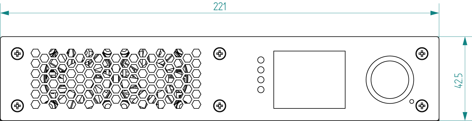
Side View
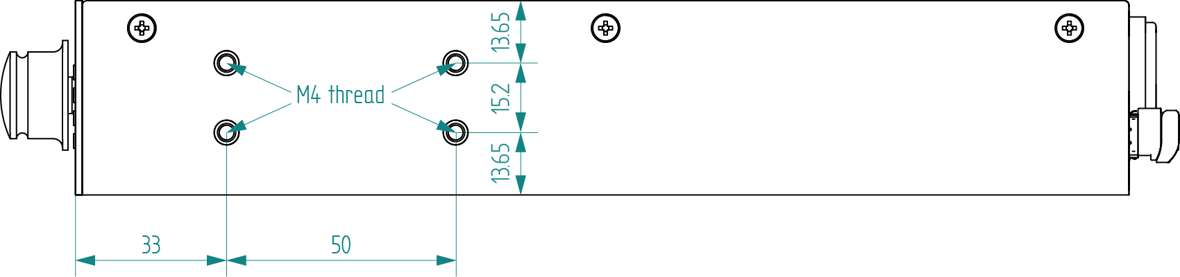
Bottom View
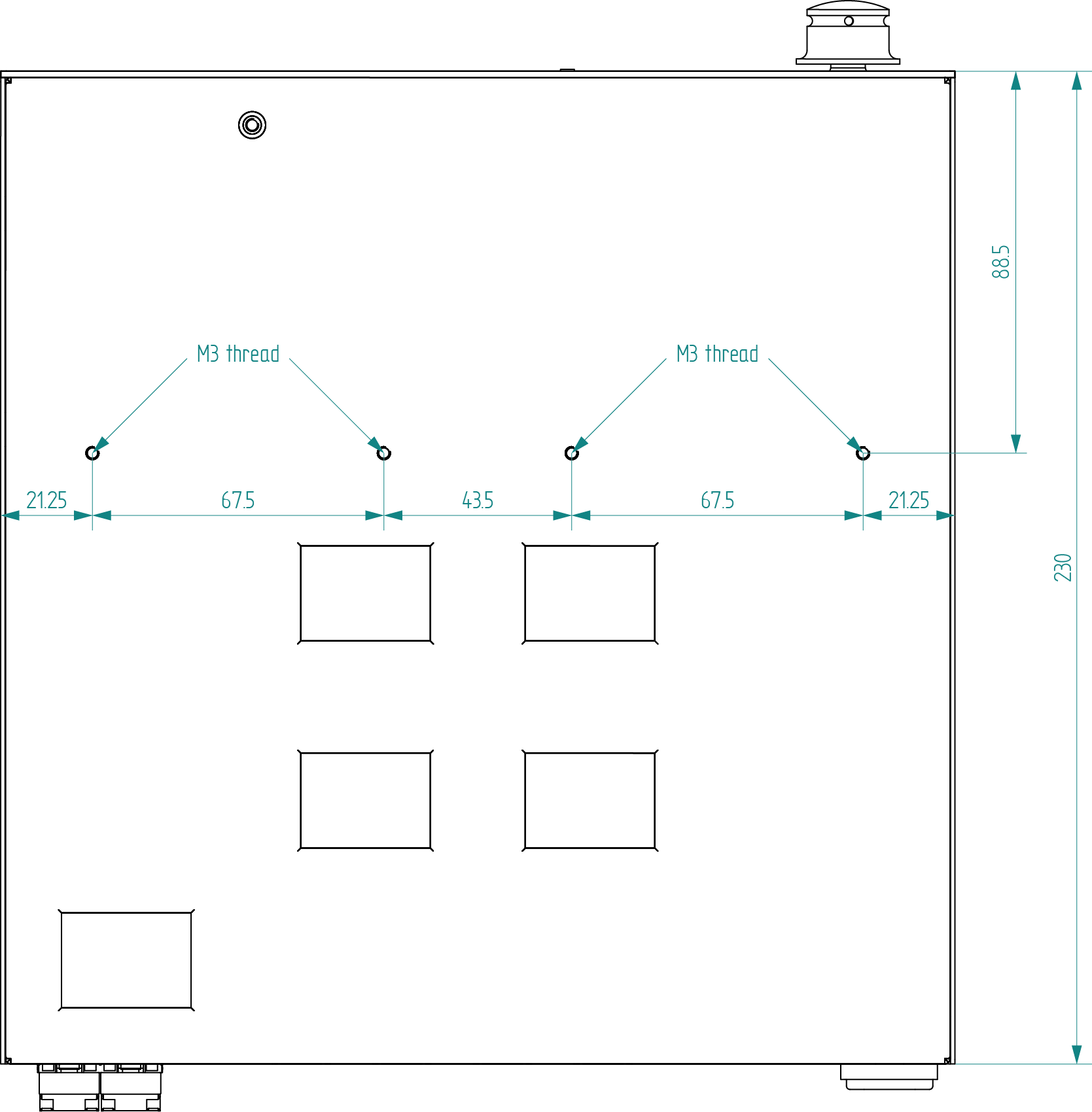
15.10.2. UBEX R-series Endpoint Devices
The following drawings present the physical dimensions of the UBEX R-series endpoints. Dimensions are in mm.
Affected models:
▪UBEX-PRO20-HDMI-R100 2xMM-2xDUO
▪UBEX-PRO20-HDMI-R100 2xMM-QUAD
▪UBEX-PRO20-HDMI-R100 2xSM-2xDUO
▪UBEX-PRO20-HDMI-R100 2xSM-QUAD
▪UBEX-PRO20-HDMI-R100 2xSM-BiDi-DUO
Front View
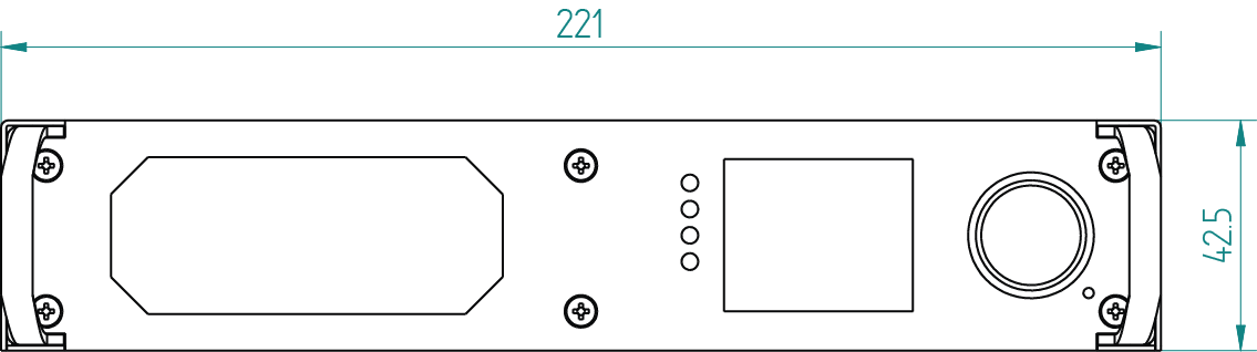
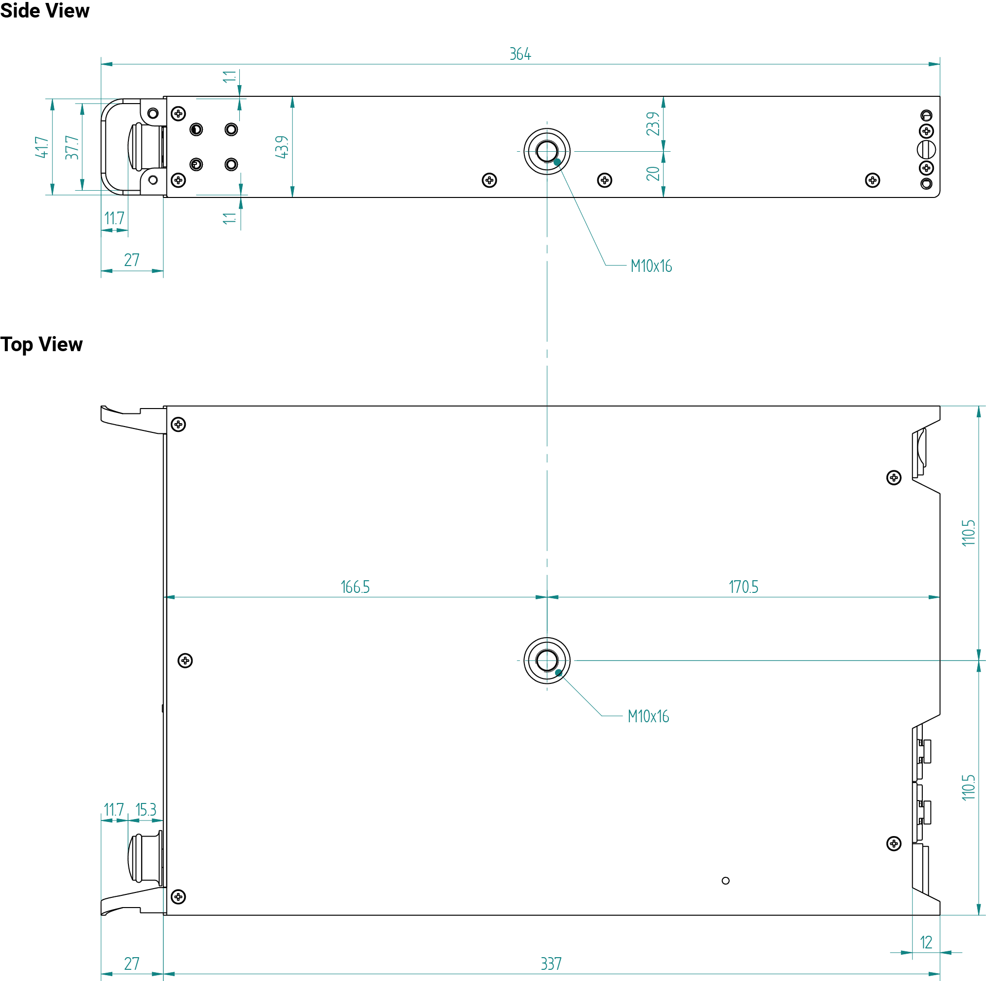
15.10.3. UBEX-MMU-X200
The following drawings present the physical dimensions of the Matrix Management Unit. Dimensions are in mm.
Affected model:
▪UBEX-MMU-X200
Front View (1:1)
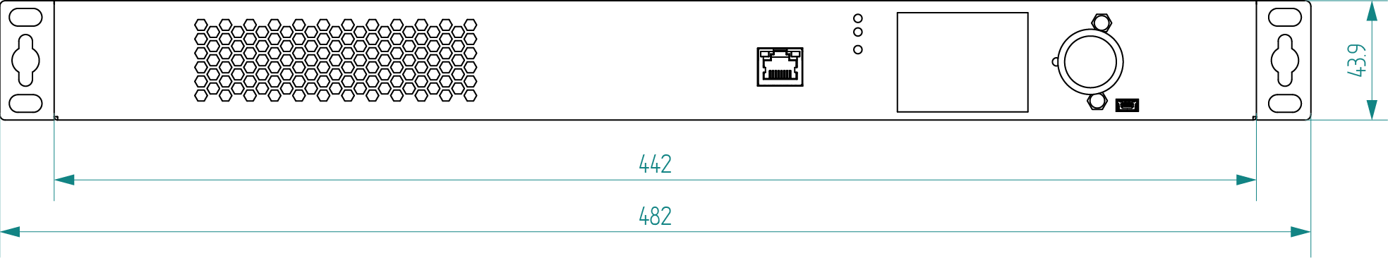
Top View (1:1)
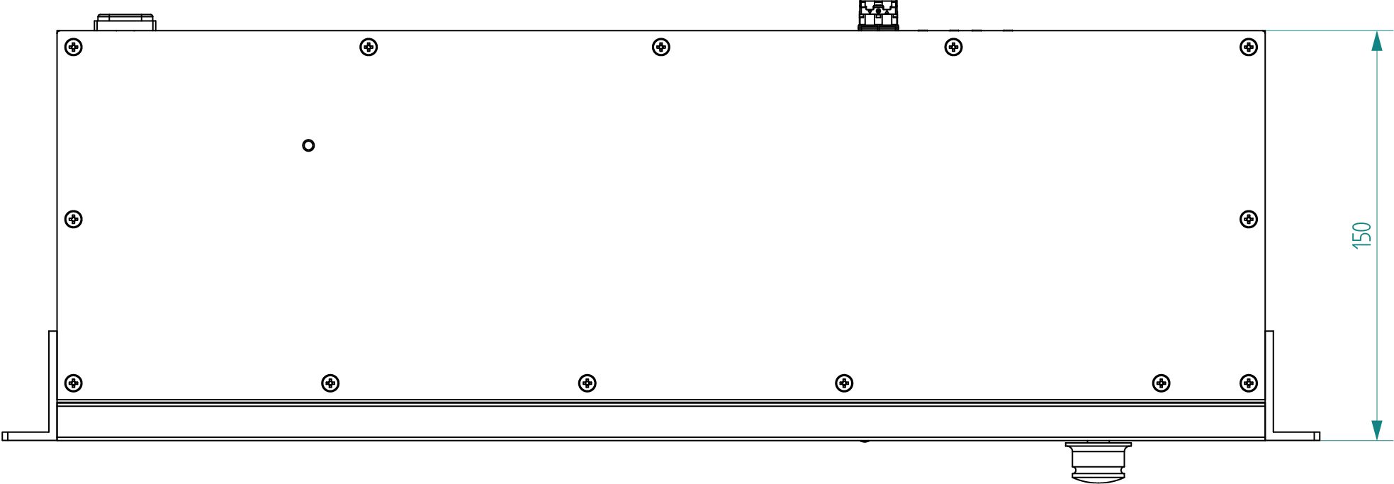
Side View (2:1)
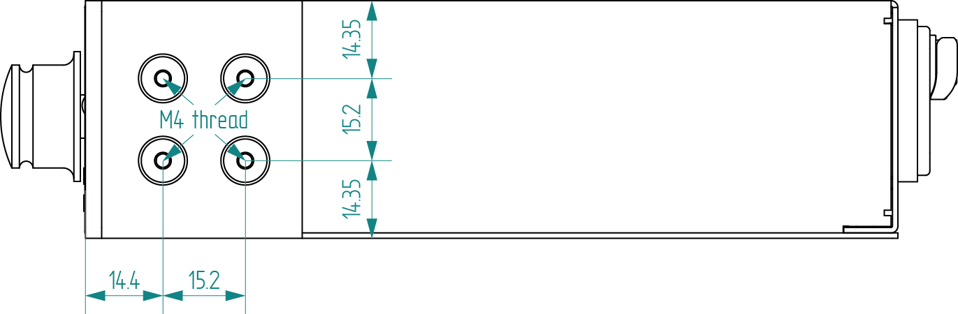
15.11. Maximum Cable Extensions
15.11.1. F-series Endpoints / MMU
The maximum fiber cable extension of the F-series endpoint devices and the MMU depends on the installed SFP / SFP+ modules. Always read the specification of the modules.
10GBASE-T SFP+ Copper RJ45 Modules
F-series endpoint devices can be installed with 10GBASE-T SFP+ to RJ45 modules. Lightware recommends FS 10GBASE-T SFP+ Copper RJ-45 (Juniper Networks EX-SFP-10GE-T Compatible) transceiver module which is able to apply up to 80 meters cable extension in case of CAT6A or CAT7 cable types.
ATTENTION!Always apply equal length copper cables for both SFP+ to RJ45 modules in case of 20G signal transmission. Different cable lengths may cause data package loss.
TIPS AND TRICKS:AWG number shows the quality of the copper cable. The number is smaller, the quality of the cable is better and its resistance is even smaller. Smaller resistance makes possible applying longer cable.
The R-series endpoint devices are built with pre-installed SFP+ modules inside the enclosure. The maximum fiber cable extension depends on the modules. The SFP+ modules can be changed by the user, see the details in the SFP+ Module Changing in R-series Endpoints section.
2xMM-2xDUO / 2xMM-QUAD
|
Multimode fiber optical cables |
|||
|
OM1 |
OM2 |
OM3 |
OM4 |
|
(62.5/125) |
(50/125) |
(50/125) |
(50/125) |
|
Not supported |
300 m |
400 m |
|
2xSM-2xDUO / 2xSM-QUAD / 2xSM-BiDi-DUO
|
Singlemode fiber optical cables |
|
|
OS1 |
OS2 |
|
(62.5/125) |
(50/125) |
|
2000 m |
10000 m |
15.12. Bandwidth Requirements of the Resolutions
15.12.1. Calculation Formula
The required bandwidth of a resolution can be calculated by a simple formula. Using the formula, the user can get the bandwidth requirement of any resolution. #bandwidth
[Horizontal pixels] x [Vertical pixels] x [Refresh rate] x [Color depth] x [Color sampling multiplier] x 1.08 = {Bandwidth}
The 1.08 multiplier is the overhead, which includes the data that is transmitted together with the AV signal.
Color Sampling Multiplier
The final result depends on the applied color sampling. In case of 4:4:4, the bandwidth is the same, so the multiplier will be 1. In case of 4:2:2 color sampling, the number will be the 66% of it; in case of 4:2:0, it is halved.
|
Color sampling |
Color sampling multiplier |
|---|---|
|
4:4:4 |
1 |
|
4:2:2 |
0.66 |
|
4:2:0 |
0.5 |
Let's see an example. Here is an one of the most used resolution: 4K UHD 60Hz 4:4:4 8bit/ch
The formula: 3840 x 2160 x 60 x 24 x 1 x 1.08 = 12,899,450,880 ≈ 12.9 Gbps
Examples
The following examples show how it can be applied to it in the real life.
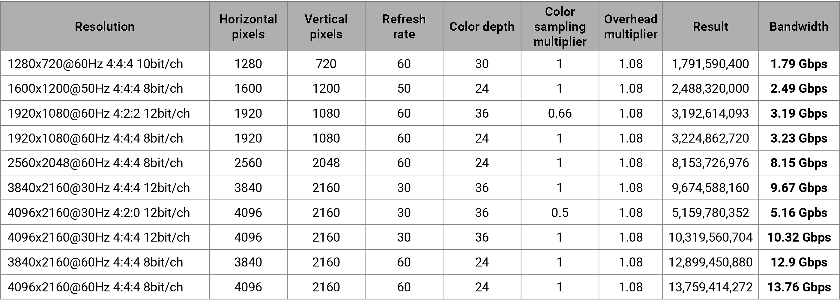
15.12.2. Table of the Most Used Resolutions
F and R series Endpoint Models
DIFFERENCE:This table refers to the UBEX-PRO20-HDMI-F100, -F110, -F111, -F120, -F121 and R100 series endpoint models only. The F130 model operates with different bandwidth limitaions, see the dedicated table of this model in the F130 Endpoint Model section (next page).
The following table contains the bandwidth requirement when transmitting one or two AV signals together. The table is grouped by resolution, color space, and color depth. The values are in Gb/s.
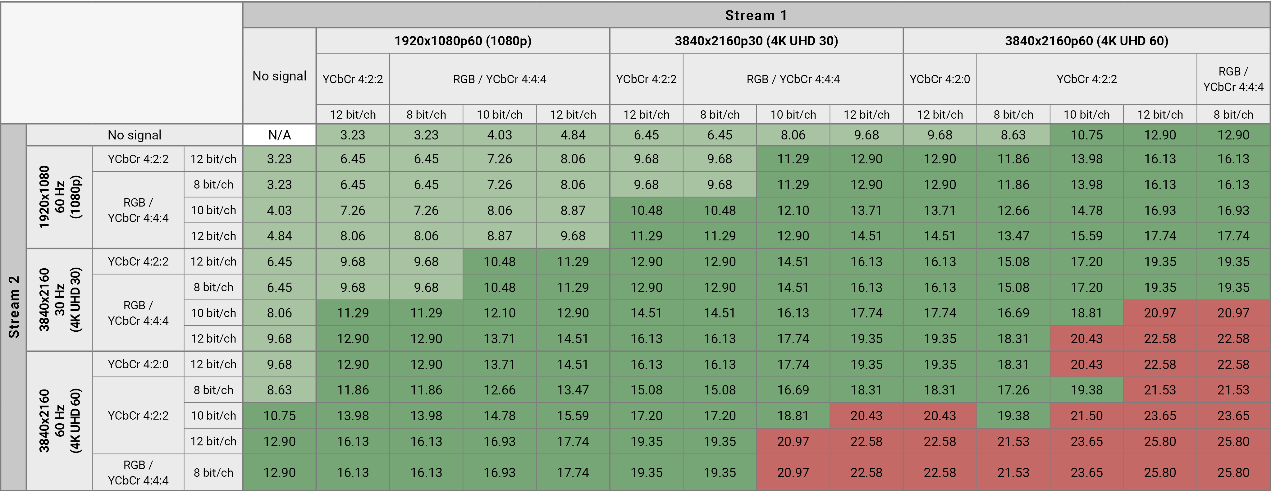

DIFFERENCE:This table refers to the UBEX-PRO20-HDMI-F130 endpoint model only.
ATTENTION!In case of F130 endpoint model the USB KVM and the USB 2.0 transmission reserves 2 Gbps bandwith also in LEX and REX modes, so the the available total bandwidth is 8 Gbps in case of 1x10G SFP+ connection and 18 Gbps in case of 2x10G SFP+ connection. In case of disabled mode, this restriction is ceased and the available bandwidth is up to 20 Gbps.
The following table contains the bandwidth requirement when transmitting one or two AV signals together. The table is grouped by resolution, color space, and color depth. The values are in Gb/s.
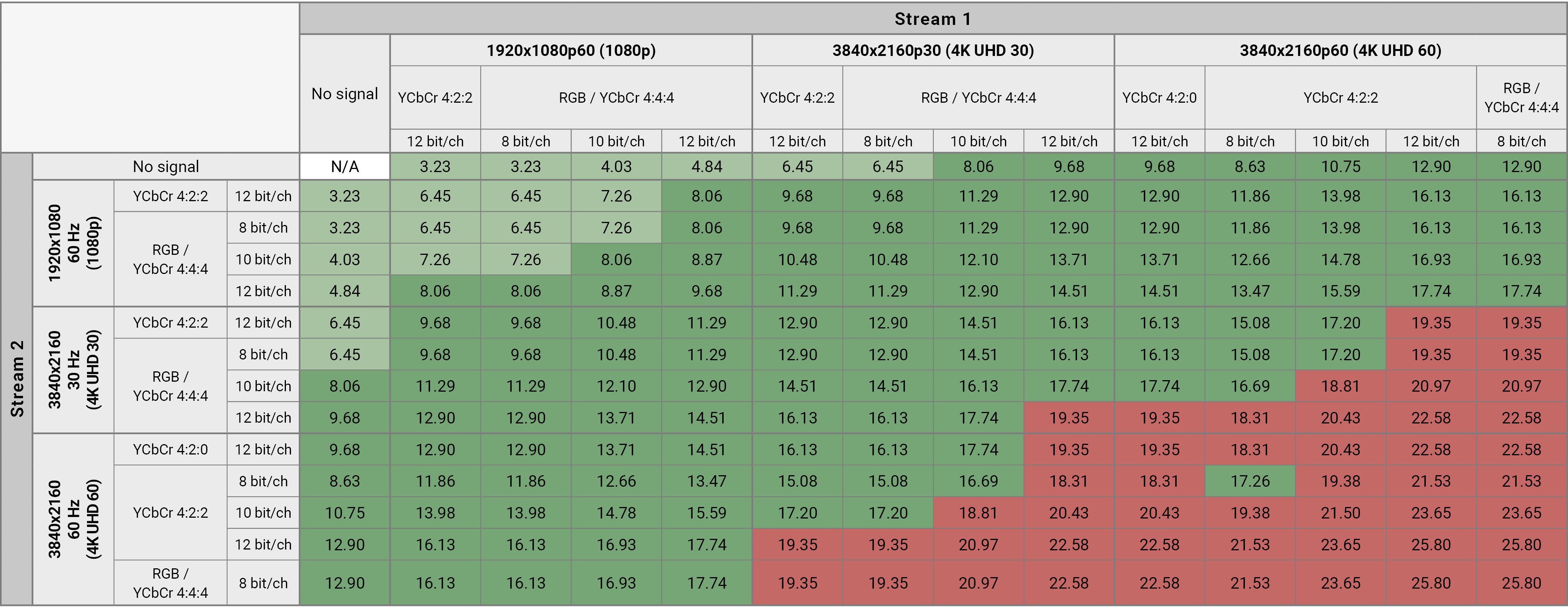

Inputs and outputs of audio devices are symmetric or asymmetric. The main advantage of the symmetric lines is the better protection against the noise, therefore they are widely used in the professional audio industry. Symmetric audio is most often referred to as balanced audio, as opposed to asymmetric, which is referred to as unbalanced audio. Ligthware products are usually built with 5-pole Phoenix connectors, so we would like to help users assemble their own audio cables. See the most common cases below.
▪Symmetric and asymmetric lines can be linked with passive accessories (e.g. special cables), but in this case half of the line level is lost.
▪There are numerous types of regularly used connector and cable types to connect audio devices. Please always make sure that a connector or cable fits your system before use.
▪Never join the phase-inverted (negative, cold or -) poles (either right or left) to the ground or to each other on the output side, as this can damage the unit.
▪Use a galvanic isolation in case of a ground loop.
The device is built with a 3-pole Phoenix connector. See the examples below of connecting to a DCE (Data Circuit-terminating Equipment) or a DTE (Data Terminal Equipment) type device:
|
Lightware device and a DCE D-SUB 9 and Phoenix |
Lightware device and a DTE D-SUB 9 and Phoenix |
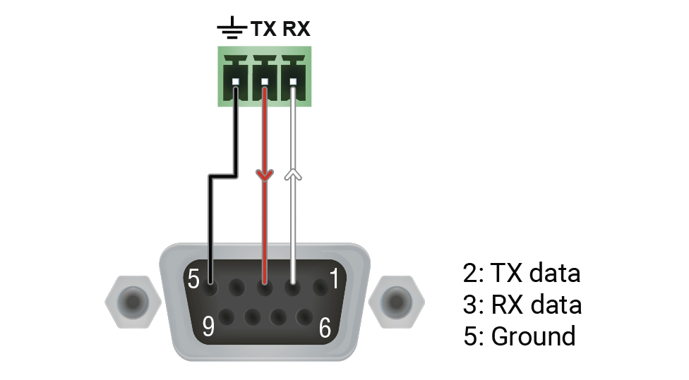
|
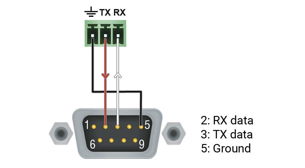
|
The Pinout of the 5-pole Phoenix Connector
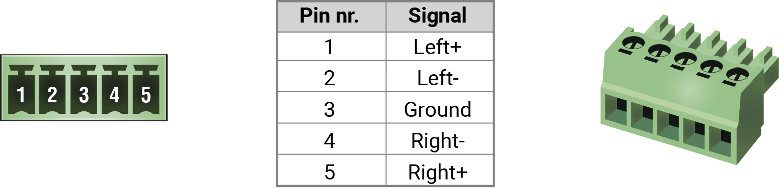
Compatible Plug Type: Phoenix® Combicon series (3.5mm pitch, 5-pole), type: MC 1.5/5-ST-3.5.
From Unbalanced Output to Balanced Input
|
2 x 6.3 (1/4") TS - Phoenix |
2 x RCA - Phoenix |
3.5 (1/8") TRS - Phoenix |
||
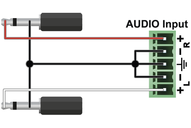
|
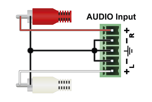
|
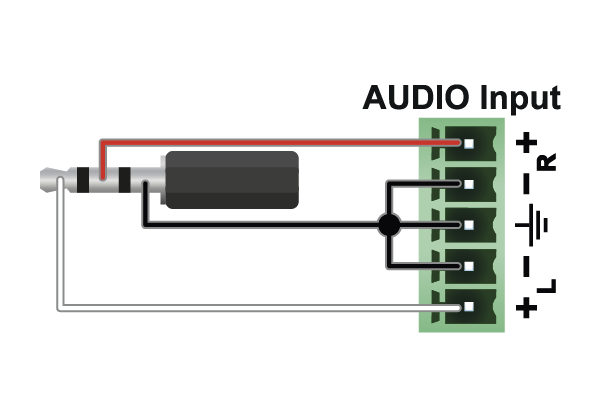
|
From Balanced Output to Unbalanced Input
|
Phoenix - 2 x 6.3 (1/4") TS |
Phoenix - 2 x RCA |
Phoenix - 3.5 (1/8") TRS |
||
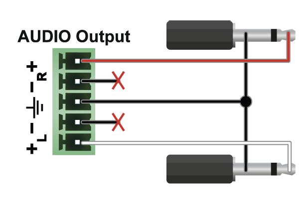
|
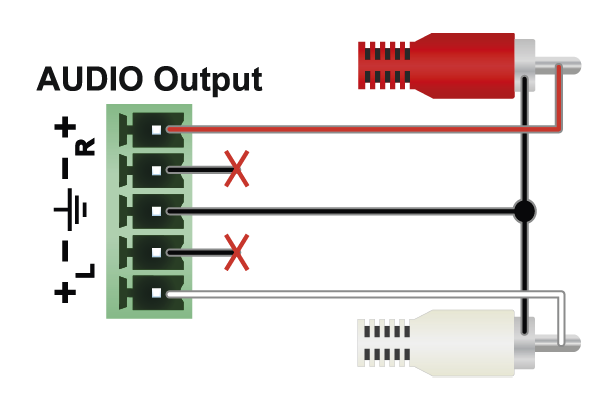
|
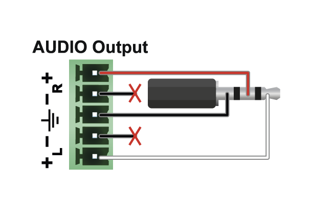
|
From Balanced Output to Balanced Input
|
Phoenix - 2 x 6.3 (1/4") TRS |
Phoenix - 2 x XLR |
2 x 6.3 TRS (1/4") - Phoenix |
||
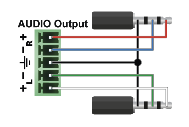
|
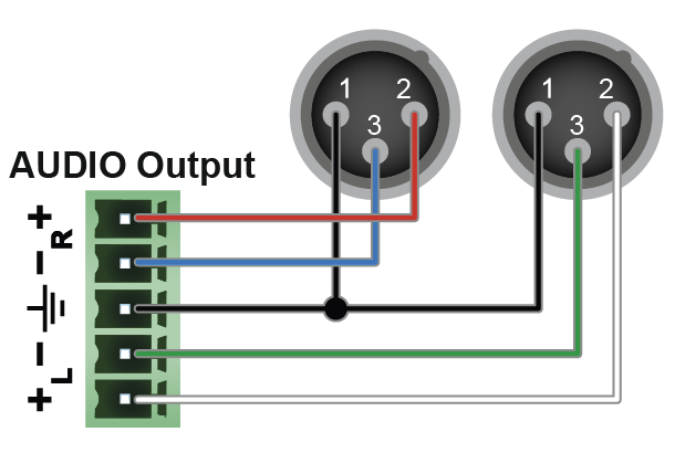
|
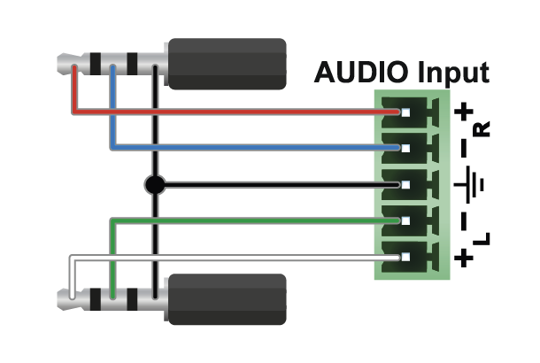
|
||
|
2 x XLR - Phoenix |
Phoenix - Phoenix |
|||
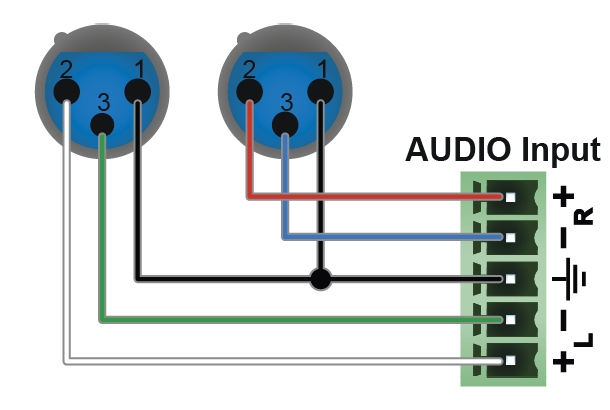
|
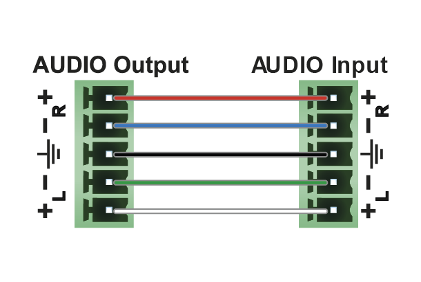
|
What do you want to do? The following link collection helps to find the related section for your current activity. The collection is grouped by topic category and within that is in alphabetical order.
|
Activity |
Front panel |
LDC / Built-in Web |
LW3 command |
|---|---|---|---|
|
General - MMU |
|||
|
Backup/restore |
- |
- |
|
|
Date and time settings |
|||
|
Device label change |
- |
||
|
Factory default restore |
|||
|
Firmware version query |
|||
|
LCD screen brightness |
- |
||
|
Log file export |
- |
- |
|
|
NTP - enable/disable |
- |
||
|
NTP server address setting |
- |
||
|
Restarting the device |
|||
|
Software resetting the device |
- |
||
|
General - Endpoints |
|||
|
Application mode change (Extender / Matrix) |
- |
- |
|
|
Bootload mode setting |
- |
||
|
Control lock |
- |
||
|
Dark mode |
|||
|
Device label change (RX/TRX) |
- |
||
|
Device label change (TX/TRX) |
- |
||
|
Factory default restore |
- |
||
|
Firmware version query (RX) |
|||
|
Firmware version query (TX) |
|||
|
Firmware version query (TRX) |
|||
|
Identify the device (RX/TRX) |
- |
||
|
Identify the device (TX/TRX) |
- |
||
|
Jog dial control knob - rotary direction (RX) |
|||
|
Jog dial control knob - rotary direction (TRX) |
|||
|
Jog dial control knob - rotary direction (TX) |
|||
|
LCD screen brightness (RX) |
|||
|
LCD screen brightness (TRX) |
|||
|
LCD screen brightness (TX) |
|||
|
MAC address query (RX/TRX) |
|||
|
MAC address query (TX/TRX) |
|||
|
Operation mode (TX, RX, or TRX) change |
- |
||
|
Operation mode (TX, RX, or TRX) query |
|||
|
Restarting the device |
|||
|
Endpoint Management |
|||
|
MAC address query (RX/TRX) |
|||
|
MAC address query (TX/TRX) |
|||
|
Query the claiming status of an endpoint |
- |
- |
|
|
Query the connection status of an endpoint |
- |
- |
|
|
Query the number of connected endpoints |
- |
||
|
Query the number of connected transmitters |
- |
||
|
Query the number of connected receivers |
- |
||
|
Query the number of connected transceivers |
- |
||
|
Re-order the endpoints (Device Map) |
- |
||
|
Unclaiming an endpoint |
- |
- |
|
|
Unclaiming all endpoints |
- |
- |
|
|
Crosspoint settings |
|||
|
Searching a source / destination / device / tag |
- |
- |
|
|
Switching the audio stream to one destination |
- |
||
|
Switching an audio stream to all destinations |
- |
||
|
Switching a USB K+M stream to one destination |
- |
||
|
Switching a USB K+M stream to all destinations |
- |
||
|
Switching the video stream to one destination |
- |
||
|
Switching a video stream to all destinations |
- |
||
|
Query the number of the destination ports |
- |
- |
|
|
Query the number of the source ports |
- |
- |
|
|
Video (Sources) |
|||
|
Color depth setting |
- |
||
|
Color range setting |
- |
||
|
Color space converter setting |
- |
||
|
HDCP setting |
- |
||
|
Icon setting |
- |
- |
|
|
Port status query |
|||
|
Scaler - Image position |
- |
||
|
Scaler - Forced resolution |
- |
||
|
Scaler - Scaling mode |
- |
||
|
Stream enable/disable |
- |
||
|
Stream naming |
- |
||
|
Stream status query (TRX) |
|||
|
Stream status query (TX) |
|||
|
Tags - Adding a new tag |
- |
||
|
Tags - Delete a tag |
- |
||
|
Tags - Delete all the tags |
- |
||
|
Tags - Query the tags of the stream |
- |
||
|
Tile resolution for multiviewer |
- |
- |
|
|
Video (Destinations) |
|||
|
Color depth setting |
- |
||
|
Color range setting |
- |
||
|
Color space converter setting |
- |
||
|
Freeze the signal |
- |
||
|
HDCP mode setting |
- |
||
|
Icon setting |
- |
- |
|
|
Port status query |
|||
|
Scaler - Image position |
- |
||
|
Scaler - Forced resolution |
- |
||
|
Scaler - Scaling mode |
- |
||
|
Stream enable/disable |
- |
||
|
Stream naming |
- |
||
|
Stream status query (RX) |
|||
|
Stream status query (TRX) |
|||
|
Tags - Adding a new tag |
- |
||
|
Tags - Delete a tag |
- |
||
|
Tags - Delete all the tags |
- |
||
|
Tags - Query the tags of the stream |
- |
||
|
Timing mode setting |
- |
||
|
Unfreeze the signal |
- |
||
|
Video Wall Configuration |
|||
|
Color space converter setting |
- |
||
|
Crosspoint setting |
- |
||
|
Display parameters - query |
- |
||
|
Display parameters - width change |
- |
||
|
Display parameters - height change |
- |
||
|
Display parameters - top bezel size change |
- |
||
|
Display parameters - bottom bezel size change |
- |
||
|
Display parameters - left bezel size change |
- |
||
|
Display parameters - right bezel size change |
- |
||
|
Display parameters - horizontal gap size change |
- |
||
|
Display parameters - vertical gap size change |
- |
||
|
Layout - activate |
- |
||
|
Layout - create |
- |
||
|
Layout - delete |
- |
||
|
Layout - delete all |
- |
||
|
Layout - identify |
- |
||
|
Layout - name setting |
- |
||
|
Layout - query the active one |
- |
||
|
No sync screen setting |
- |
||
|
Output - assing |
- |
||
|
Output - assignment query |
- |
||
|
Output - unassing |
- |
||
|
Output - unassing all |
- |
||
|
Tags - Adding a new tag to the zone |
- |
||
|
Tags - Delete a tag of the zone |
- |
||
|
Tags - Delete all the tags of the zone |
- |
||
|
Tags - Query the static tags of the zone |
- |
||
|
Tags - Query the user tags of the zone |
- |
||
|
Timing mode setting |
- |
||
|
Resolution mode setting |
- |
||
|
Resolution setting |
- |
||
|
Video wall - background color setting |
- |
||
|
Video wall - create |
- |
||
|
Video wall - delete |
- |
||
|
Video wall - identify |
- |
||
|
Video wall - name setting |
- |
||
|
Video wall - size modify |
- |
||
|
Video wall - size query |
- |
||
|
Video wall - state setting |
- |
||
|
Video wall - state query |
- |
||
|
Zone - assing display device |
- |
||
|
Zone - unassing all display device |
- |
||
|
Zone - unassing display device |
- |
||
|
Zone - background color setting |
- |
||
|
Zone - create |
- |
||
|
Zone - delete |
- |
||
|
Zone - delete all |
- |
||
|
Zone - identify |
- |
||
|
Zone - name setting |
- |
||
|
Zone - size query |
- |
||
|
Multiviewer Configuration |
|||
|
Canvas resolution |
- |
||
|
Color depth setting (destination) |
- |
||
|
HDCP setting (destination) |
- |
||
|
Identify display |
- |
||
|
Identify stream |
- |
||
|
Layer order |
- |
||
|
Source MUX settings |
- |
||
|
Tile enable/disable |
- |
||
|
Tile opacity |
- |
||
|
Tile position |
- |
||
|
Tile size (resolution) |
- |
||
|
Tile status query |
- |
||
|
Audio |
|||
|
Analog audio balance setting (input) |
- |
||
|
Analog audio balance setting (output) |
- |
||
|
Analog audio gain setting |
- |
||
|
Analog audio output status query |
- |
||
|
Analog audio volume setting in dB (input) |
- |
||
|
Analog audio volume setting in dB (output) |
- |
||
|
Analog audio volume setting in percent (input) |
- |
||
|
Analog audio volume setting in percent (output) |
- |
||
|
Mute/unmute the analog audio output |
- |
||
|
Stream destination enable/disable |
- |
||
|
Stream destination naming |
- |
||
|
Stream source enable/disable |
- |
||
|
Stream source naming |
- |
||
|
Stream status query |
- |
||
|
Port status query |
- |
||
|
Tags - Adding a new tag |
- |
||
|
Tags - Delete a tag |
- |
||
|
Tags - Delete all the tags |
- |
||
|
Tags - Query the tags of the stream |
- |
||
|
EDID Management |
|||
|
Copy / save a user EDID |
- |
||
|
Create EDID |
- |
- |
|
|
Delete a user EDID |
- |
||
|
Edit an EDID |
- |
- |
|
|
Query the resolution of an emulated EDID |
|||
|
Reset the emulated EDIDs |
- |
||
|
Switch (emulate) |
- |
||
|
Diagnostics |
|||
|
Diagnostics download |
- |
- |
|
|
Frame detector |
- |
- |
|
|
No sync screen (test pattern) color |
- |
||
|
No sync screen (test pattern) mode |
- |
||
|
Network - MMU |
|||
|
DHCP (dynamic IP address) setting |
|||
|
Gateway address change (static) |
|||
|
IP address query |
|||
|
IP address setting (static) |
|||
|
Subnet mask change (static) |
|||
|
Ethernet Port Configuration - Endpoints |
|||
|
Ethernet mode setting |
- |
||
|
Port enable/disable |
- |
||
|
Port naming |
- |
||
|
Tags - Adding a new tag |
- |
||
|
Tags - Delete a tag |
- |
||
|
Tags - Delete all the tags |
- |
||
|
Tags - Query the tags of the port |
- |
||
|
RS-232 Interface - MMU |
|||
|
RS-232 port configuration |
- |
- |
|
|
RS-232 Interface - Endpoints |
|||
|
Command injection TCP port number changing |
- |
||
|
Command injection TCP port numbers remapping |
- |
- |
|
|
Port enable/disable |
- |
||
|
Port naming |
- |
||
|
RS-232 port configuration |
- |
||
|
Sending ASCII-format text |
- |
- |
|
|
Sending ASCII-format message |
- |
||
|
Sending binary message |
- |
- |
|
|
Tags - Adding a new tag |
- |
||
|
Tags - Delete a tag |
- |
||
|
Tags - Delete all the tags |
- |
||
|
Tags - Query the tags of the port |
- |
||
|
Query the current configuration |
- |
||
|
USB K+M Interface (F120 / F121 models) |
|||
|
Query the name of the destination USB port |
- |
||
|
Query the number of destination USB ports |
- |
- |
|
|
Query the name of the emulated USB port |
- |
||
|
Query the number of emulated USB ports |
- |
- |
|
|
Setting the name of the destination USB port |
- |
||
|
Setting the name of the emulated USB port |
- |
||
|
Switching a USB K+M stream to all destinations |
- |
||
|
Switching a USB K+M stream to one destination |
- |
||
|
Tags - Adding a new tag |
- |
- |
|
|
Tags - Delete a tag |
- |
- |
|
|
Tags - Delete all the tags |
- |
- |
|
|
Tags - Query the tags of the port |
- |
- |
|
|
USB KVM and USB 2.0 Interface (F130 model) |
|||
|
Query the name of the destination USB HID port |
- |
||
|
Query the number of destination USB HID ports |
- |
- |
|
|
Query the name of the emulated USB HID port |
- |
||
|
Query the number of emulated USB HID ports |
- |
- |
|
|
Query the MAC address of the Icron module |
|||
|
Remote (REX) / Local (LEX) operation mode setting |
- |
- |
|
|
Setting the name of the destination USB HID port |
- |
||
|
Setting the name of the emulated USB HID port |
- |
||
|
Switching a USB KVM stream to all destinations |
- |
||
|
Switching a USB KVM stream to one destination |
- |
||
|
Tags - Adding a new tag |
- |
- |
|
|
Tags - Delete a tag |
- |
- |
|
|
Tags - Delete all the tags |
- |
- |
|
|
Tags - Query the tags of the port |
- |
- |
|
|
Infrared Interface - Endpoints |
|||
|
Change command injection port number |
- |
||
|
Enable output signal modulation |
- |
- |
|
|
Enable the port |
- |
||
|
Name setting - input port |
- |
||
|
Name setting - output port |
- |
||
|
Sending pronto hex message in big-endian format |
- |
- |
|
|
Sending pronto hex message in little-endian format |
- |
||
|
Tags - Adding a new tag |
- |
||
|
Tags - Delete a tag |
- |
||
|
Tags - Delete all the tags |
- |
||
|
Tags - Query the tags of the port |
- |
||
|
AV Network Management |
|||
|
Bandwidth limitation indicator query |
- |
||
|
Bandwidth query |
|||
|
General SFP+ interface status query (RX) |
|||
|
General SFP+ interface status query (TRX) |
|||
|
General SFP+ interface status query (TX) |
|||
|
Health status query for endpoints |
|||
|
Link aggregation status query (RX) |
- |
||
|
Link aggregation status query (TRX) |
- |
||
|
Link aggregation status query (TX) |
- |
||
|
Link status query for endpoints |
|||
|
SFP+ module information query (RX) |
|||
|
SFP+ module information query (TRX) |
|||
|
SFP+ module information query (TX) |
|||
|
Endpoint License |
|||
|
Query the description of the license |
- |
||
|
Query the endpoint limitation |
- |
||
|
Query the name of the license |
- |
||
|
Query the status of the license |
- |
||
|
Removal of the license |
- |
||
|
Uploading a new license |
- |
- |
|
|
Centralized Firmware Update |
|||
|
Canceling firmware update procedure |
- |
||
|
Firmware update progress query |
- |
||
|
Firmware update status query |
- |
||
|
Installed firmware package version query |
- |
||
|
Last message of the firmware update query |
- |
||
|
Restarting firmware update procedure |
- |
||
|
Starting firmware update procedure |
- |
||
|
Unsupported firmware packages allowing |
- |
||
This user manual contains keywords with hashtags (#) to help you find the relevant information as quick as possible.
The format of the keywords is the following:
#<keyword>
The usage of the keywords: use the Search function (Ctrl+F / Cmd+F) of your PDF reader application, type the # (hashtag) character and the wished keyword.
The #new special keyword indicates a new feature/function that has just appeared in the latest firmware or software version.
Example
#dhcp
This keyword is placed at the DHCP (dynamic IP address) setting in the front panel operation, the Lightware Device Controller (LDC) and the LW3 programmer's reference section.
The following list contains all hashtag keywords placed in the document with a short description belonging to them. The list is in alphabetical order by the hashtag keywords.
|
Hashtag Keyword |
Description |
|---|---|
|
#advancedview |
Advanced view window |
|
#analogaudio |
Analog audio related settings |
|
#applicationmode |
Application mode (extender/matrix) setting |
|
#audio |
Audio related settings |
|
#backup |
Configuration cloning (backup) |
|
#balance |
Balance (for analog audio) setting |
|
#bandwidth |
Calculation of the bandwidth requirement information |
|
#bootload |
Bootload mode setting |
|
#builtinweb |
Built-in web for MMU |
|
#colordepth |
Color depth setting |
|
#colorrange |
Color range setting |
|
#colorspace |
Color space converter related settings |
|
#configurationcloning |
Configuration cloning (backup) |
|
#crosspoint |
Crosspoint switch setting |
|
#csc |
Color space converter related settings |
|
#darkmode |
Dark mode setting |
|
#date |
Date setting in the MMU |
|
#devicelabel |
Device label |
|
#devicemap |
Device map in LDC |
|
#dhcp |
Dynamic IP address (DHCP) setting |
|
#disconnect |
Disconnecting stream setting (crosspoint) |
|
#edid |
EDID related settings |
|
#endpointmanagement |
Endpoint management for the MMU |
|
#ethernet |
Ethernet port settings |
|
#extendermode |
Application mode (extender/matrix) setting |
|
#factory |
Factory default settings |
|
#find |
Search function in LDC |
|
#firmwareversion |
Firmware version query |
|
#framedetector |
Frame detector in LDC |
|
#frc |
Frame rate converter related settings |
|
#freerun |
Timing mode setting |
|
#freeze |
Signal freeze |
|
#gain |
Gain (for analog audio) setting |
|
#gridview |
Grid view in LDC |
|
#hdcp |
HDCP-encryption related setting |
|
#health |
System monitoring (health) related information |
|
#icron |
USB KVM related settings (F130 variant) |
|
#identifydisplay |
Identify display feature |
|
#identifyme |
Identify me (identify the device) feature |
|
#identifystream |
Identify stream feature |
|
#infra |
Infrared port related settings |
|
#ipaddress |
IP address related settings |
|
#ir |
Infrared port related settings |
|
#jogdial |
Jog dial control knob related settings |
|
#km |
USB K+M related settings (F120 variant) |
|
#kvm |
USB KVM related settings (F130 variant) |
|
#label |
Device label |
|
#layout |
Videowall layout related settings |
|
#license |
Endpoint license related settings |
|
#link |
SFP+ link related information |
|
#log |
System log |
|
#mac |
MAC address query |
|
#matrixmode |
Application mode (extender/matrix) setting |
|
#message |
Message sending via communication ports |
|
#multiviewer |
Multiviewer related settings |
|
#mute |
Mute (for analog audio) setting |
|
#mux |
Source multiplexer (MUX) related settings |
|
#network |
Network (IP address) related settings |
|
#new |
New feature/function of the product |
|
#nosyncscreen |
Test pattern (no sync screen) settings |
|
#ntp |
NTP (Network Time Protocol) settings |
|
#operationmode |
Operation mode (TX/RX/TRX/RXMV) setting |
|
#portstatus |
Source/destination port status query |
|
#power5v |
Power 5V mode setting |
|
#reboot |
Restarting the device |
|
#receiver |
Receiver (RX) operation mode setting |
|
#reset |
Restarting the device |
|
#restart |
Restarting the device |
|
#rotary |
Jog dial control knob related settings |
|
#rs232 |
RS-232 related settings |
|
#rs-232 |
RS-232 related settings |
|
#rx |
Receiver (RX) operation mode setting |
|
#rxmv |
Multiviewer (RXMV) operation mode setting |
|
#scaler |
Scaler related settings |
|
#seamless |
Settings for seamless switching |
|
#search |
Search function in LDC |
|
#serial |
RS-232 related settings |
|
#sfp |
SFP/SFP+ module monitoring information |
|
#softreset |
Restarting the device |
|
#sourcelocked |
Timing mode setting |
|
#sourcemux |
Source multiplexer (MUX) related settings |
|
#status |
Status query |
|
#streamenable |
Stream enable/disable setting |
|
#switch |
Crosspoint switch setting |
|
#systemmonitor |
System monitoring (health) related information |
|
#tag |
Stream/device tag related settings |
|
#terminal |
Advanced view window |
|
#testpattern |
Test pattern (no sync screen) settings |
|
#tileview |
Tile view in LDC |
|
#time |
Time setting in the MMU |
|
#timingmode |
Timing mode setting |
|
#transceiver |
Transceiver (TRX) operation mode setting |
|
#transmitter |
Transmitter (TX) operation mode setting |
|
#trx |
Transceiver (TRX) operation mode setting |
|
#tx |
Transmitter (TX) operation mode setting |
|
#unmute |
Unmute (for analog audio) setting |
|
#uplink |
SFP+ link related information |
|
#usbkm |
USB K+M related settings (F120 variant) |
|
#usbkvm |
USB KVM related settings (F130 variant) |
|
#videowall |
Videowall related settings |
|
#volume |
Volume (for analog audio) setting |
|
#vw |
Videowall related settings |
|
#web |
Built-in web for MMU |
|
#zone |
Videowall zone related settings |
15.16. Further Document Information
Symbol Legend
The following symbols and markings are used in the document:
WARNING!Safety-related information that is highly recommended to read and keep in every case!
ATTENTION!Useful information for performing a successful procedure; it is recommended to read.
DIFFERENCE:Feature or function that is available with a specific firmware/hardware version or product variant.
INFO:A notice, which contains additional information. Procedure can be successful without reading it.
DEFINITION:The short description of a feature or a function.
TIPS AND TRICKS:Ideas that you may have not known yet, but can be useful.
Navigation Buttons
|
Buttons in the PDF version |
Buttons in the HTML version |
|||
|
|
Navigate to the Table of Contents. |
|
Open the main Table of Contents. |
|
|
|
Go back to the previous page. If you clicked on a link previously, you can go back to the source page by pressing the button. |
|
Navigate to the Online User Manuals webpage. |
|
|
|
Navigate to the Bookmark page. |
|
Navigate to the Bookmark page in this User Manual. |
|
|
|
Visit www.lightware.com. |
|
Download the PDF version of the User Manual. |
|


About Printing
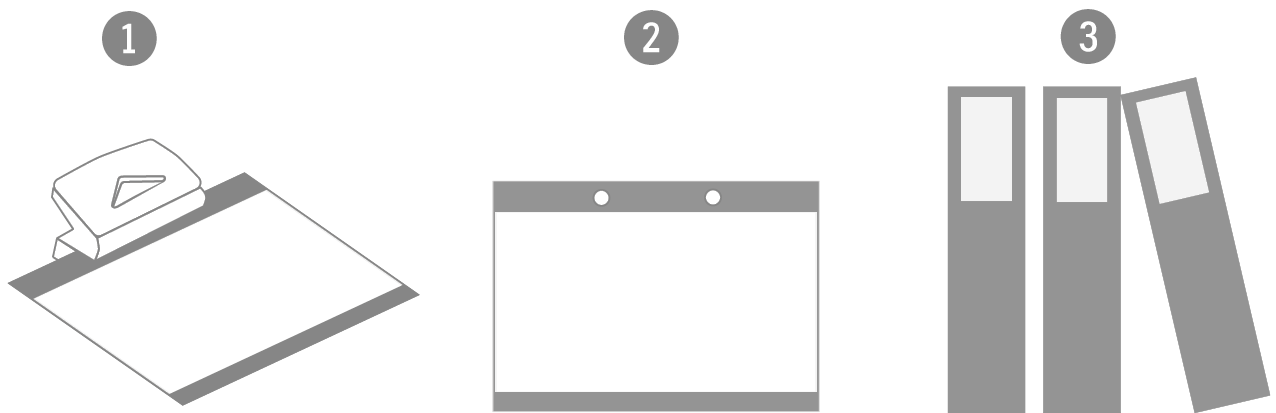
Lightware Visual Engineering supports green technologies and eco-friendly mentality. Thus, this document is made primarily for digital usage. If you need to print out a few pages for any reason, follow the recommended printing settings:
▪Page size: A4
▪Output size: Fit to page or Match page size
▪Orientation: Landscape
TIPS AND TRICKS: Thanks to the size of the original page, a border around the content (gray on the second picture below) makes it possible to organize the pages better. After punching holes in the printed pages, they can easily be placed into a ring folder.
15.17. Limited Warranty Statement
1. Lightware Visual Engineering PLC (Lightware) warrants to all trade and end user customers that any Lightware product purchased will be free from manufacturing defects in both material and workmanship for three (3) years from purchase unless stated otherwise below. The warranty period will begin on the latest possible date where proof of purchase/delivery can be provided by the customer. In the event that no proof can be provided (empty ‘Date of purchase’ field or a copy of invoice), the warranty period will begin from the point of delivery from Lightware.
1.1. 25G and MODEX product series will be subject to a seven (7) year warranty period under the same terms as outlined in this document.
1.2. If during the first three (3) months of purchase, the customer is unhappy with any aspect of a Lightware product, Lightware will accept a return for full credit.
1.3. Any product that fails in the first six (6) months of the warranty period will automatically be eligible for replacement and advanced replacement where available. Any replacements provided will be warranted for the remainder of the original unit’s warranty period.
1.4. Product failures from six (6) months to the end of the warranty period will either be repaired or replaced at the discretion of Lightware. If Lightware chooses to replace the product, then the replacement will be warranted for the remainder of the original unit’s warranty period.
2. The above-stated warranty and procedures will not apply to any product that has been:
2.1. Modified, repaired or altered by anyone other than a certified Lightware engineer unless expressly agreed beforehand.
2.2. Used in any application other than that for which it was intended.
2.3. Subjected to any mechanical or electrical abuse or accidental damage.
2.4. Any costs incurred for repair/replacement of goods that fall into the categories above (2.1., 2.2., 2.3.) will be borne by the customer at a pre-agreed figure.
3. All products to be returned to Lightware require a return material authorization number (RMA) prior to shipment, and this number must be clearly marked on the box. If an RMA number is not obtained or is not clearly marked on the box, Lightware will refuse the shipment.
3.1. The customer will be responsible for in-bound, and Lightware will be responsible for out-bound shipping costs.
3.2. Newly repaired or replaced products will be warranted to the end of the originally purchased product's warranty period.