Thank you for choosing Lightware’s HDMI-TPN series device. In the first chapter we would like to introduce the device, highlighting the most important features in the sections listed below:
1.1. Description
TPN / OPTN series Endpoints



The HDMI-TPN series transmitter and receiver devices with SDVoE technology are Lightware’s newest development allowing users to extend HDMI 2.0 signals up to 4K60 4:4:4 video resolution from a single source to multiple destinations through 10G Ethernet networks.
Beyond the benefits of sending high-resolution video over long distances, the extenders are also capable of handling various connectivity standards, including a 1G user Ethernet channel over the 10G link, as well as command injection into IR and RS-232.
The additional Gigabit Ethernet port is also a valuable addition, allowing users to connect an additional device to the network directly through the TPN extender. This is particularly useful for controlling external devices like projectors and displays.
HDCP 2.3 and basic EDID management functionality are also among the features offered by these devices, such as their connectivity and easy integration into a wide range of AV operations and with 3rd party devices, such as the Christie Terra projector.
In case of OPTN series we use standard, certificated 10 Gbps SFP+ optical modules which are plug and play, so they are interchangeable by the user. There could be either duplex multimode/singlemode module or bidirectional singlemode module.
When using direct connection in point-to-point mode, both the transmitter and receiver are compatible with Lightware’s TPX family of products.
TPN Control Unit
TPN-CTU-X50 is a Control Unit (CTU) for Lightware's TPN AV Over IP product line. With this control unit and an off-the-shelf 10G Ethernet switch installed as a crosspoint in the system, a virtual matrix can be created for TPN devices connected to the IP network as input and output endpoints.
TPN-CTU-X50 is designed to manage small TPN systems with at most 50 TPN endpoints. Technically, the device runs an SDVoE Control Server instance. It is this SDVoE Control Server instance through which the TPN endpoints (and consequently, the virtual matrix) can be reached and configured using the open SDVoE API. Thanks to this architecture, any third-party controller interface device that supports the SDVoE API can be used for managing the virtual matrix.
TPN-CTU-X50 also features Lightware Advanced Room Automation (LARA) that can be used e.g. for crosspoint switching or other automation tasks in the system.
The control unit has three independent Ethernet ports which ensures network design flexibility even in highly secure IT environments. Other control interfaces include six GPIO ports, two RS-232 interfaces, plus an OCS sensor.
Model Denomination
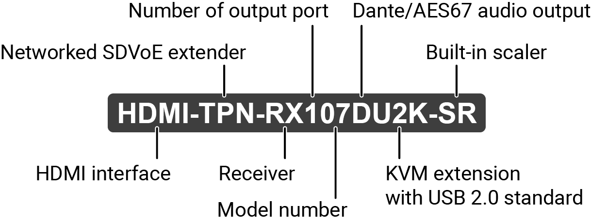
About the Serial Number
Lightware devices contain a label indicating the unique serial number of the product. The structure is the following:
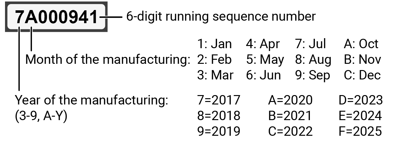
From 1st of October 2024, serial number format of Lightware devices is the following: the first two digits are of the year of manufacture, while the remaining digits make up the running sequence number.

1.2. Box Contents
Supplied Accessories
The following table describes all supplied and optional accessories of the TPN series devices by models. The optional (not-supplied) accessories can be purchased separately; please contact sales@lightware.com.
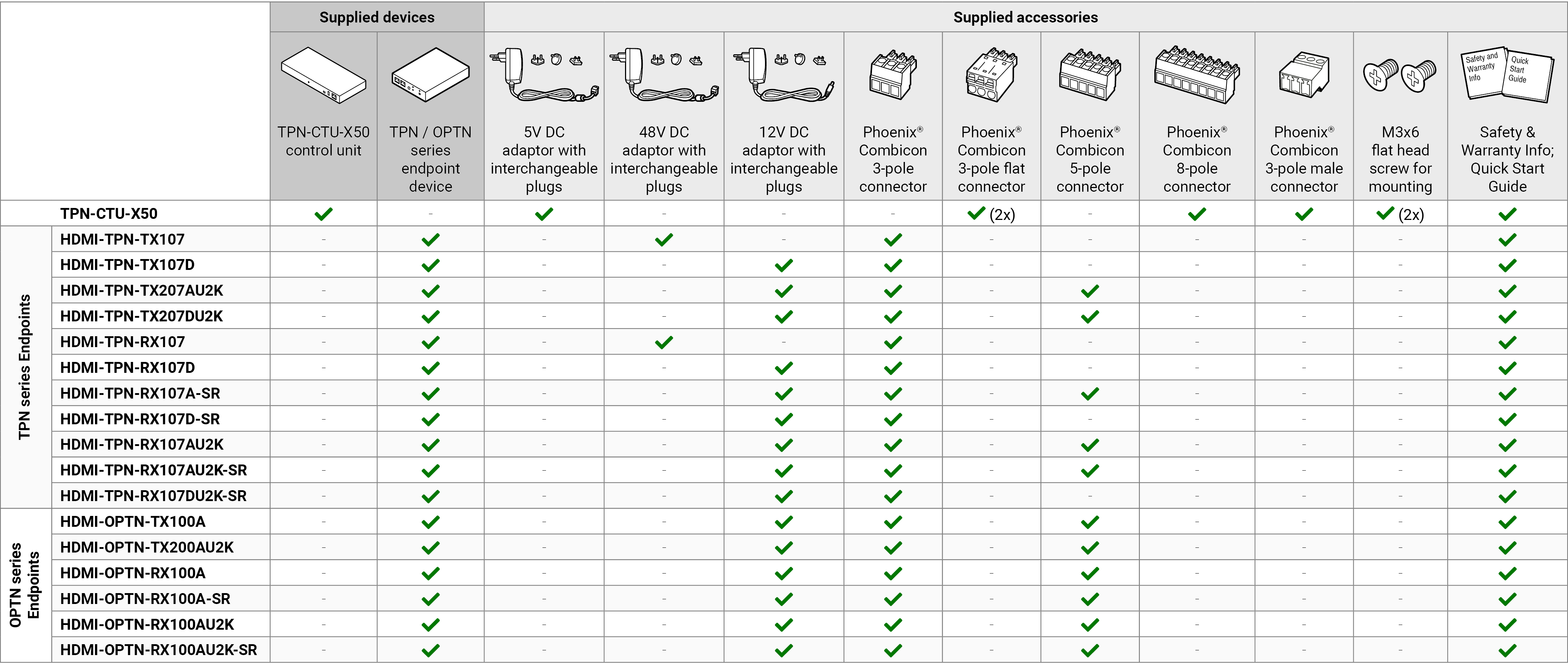
INFO:10GbE singlemode/multimode SFP+ modules can be ordered together and even separately for the OPTN endpoint devices. For the details, please contact sales@lightware.com.
1.3. Endpoint Model Comparison
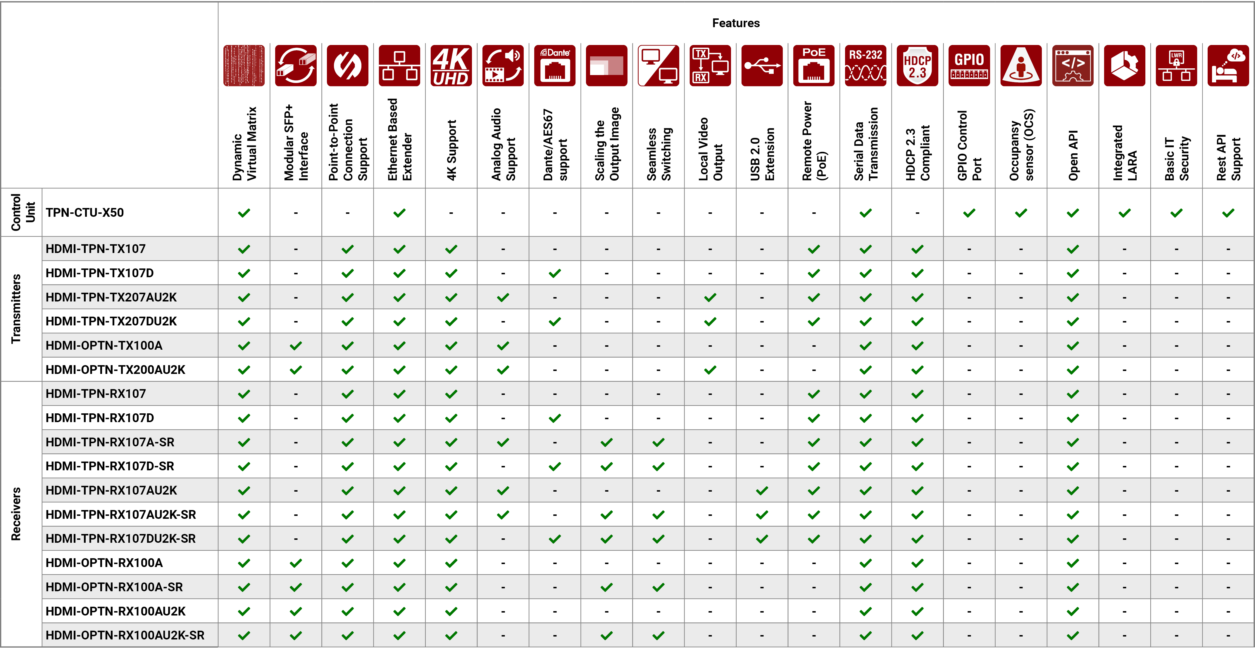
The available HDMI-TPN and HDMI-OPTN series endpoint models have different features depending on their design. The following tables contain the most important differences between the models grouped by operation mode (TX or RX).
1.3.1. Transmitters
|
AV interfaces |
SDVoE Interface |
Interface ports |
|||||||||
|---|---|---|---|---|---|---|---|---|---|---|---|
|
HDMI input |
Local HDMI output |
Analog audio output |
Dante/AES67 output |
CATx (TPN) |
Fiber optical (OPTN) |
Ethernet |
RS-232 |
Infrared output |
USB KVM |
||
|
USB-C |
USB-A |
||||||||||

|

|
|

|
|
|
|

|

|

|

|
|
|
HDMI-TPN-TX107 |
|
- |
- |
- |
|
- |
(2x) |
|
|
- |
- |
|
HDMI-TPN-TX107D |
|
- |
- |
|
|
- |
(2x) |
|
- |
- |
- |
|
HDMI-TPN-TX207AU2K |
|
|
|
- |
|
- |
(2x) |
|
- |
|
(2x) |
|
HDMI-TPN-TX207DU2K |
|
|
- |
|
|
- |
(2x) |
|
- |
|
(2x) |
|
HDMI-OPTN-TX100A |
|
- |
- |
- |
- |
|
(2x) |
|
- |
- |
- |
|
HDMI-OPTN-TX200AU2K |
|
|
|
- |
- |
|
(2x) |
|
- |
|
(2x) |


1.3.2. Receivers
|
AV interfaces |
SDVoE Interface |
Interface ports |
Features |
|||||||
|---|---|---|---|---|---|---|---|---|---|---|
|
HDMI output |
Analog audio output |
Dante/AES67 output |
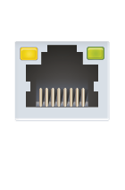
CATx (TPN) |
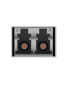
Fiber optical (OPTN) |
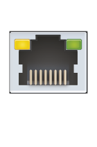
Ethernet |
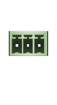
RS-232 |
Infrared output |
USB KVM |
Integrated scaler |
|
|
USB-A |
||||||||||

|
|

|
|
|
|
|

|
|

|
|
|
HDMI-TPN-RX107 |
|
- |
- |
|
- |
(2x) |
|
|
- |
- |
|
HDMI-TPN-RX107D |
|
- |
|
|
- |
(2x) |
|
- |
- |
- |
|
HDMI-TPN-RX107A-SR |
|
|
- |
|
- |
(2x) |
|
- |
- |
|
|
HDMI-TPN-RX107D-SR |
|
- |
|
|
- |
(2x) |
|
|
- |
|
|
HDMI-TPN-RX107AU2K |
|
|
- |
|
- |
(2x) |
|
- |
(6x) |
- |
|
HDMI-TPN-RX107AU2K-SR |
|
|
- |
|
- |
(2x) |
|
- |
(6x) |
|
|
HDMI-TPN-RX107DU2K-SR |
|
- |
|
|
- |
(2x) |
|
- |
(6x) |
|
|
HDMI-OPTN-RX100A |
|
|
- |
- |
|
(2x) |
|
- |
- |
- |
|
HDMI-OPTN-RX100A-SR |
|
|
- |
- |
|
(2x) |
|
- |
- |
|
|
HDMI-OPTN-RX100AU2K |
|
|
- |
- |
|
(2x) |
|
- |
(6x) |
- |
|
HDMI-OPTN-RX100AU2K-SR |
|
|
- |
- |
|
(2x) |
|
- |
(6x) |
|
1.4. Application Modes
TPN and OPTN series extender system has two main application modes:
▪Point-To-Point Connection - Point-to-point connection between a transmitter and a receiver endpoint device.

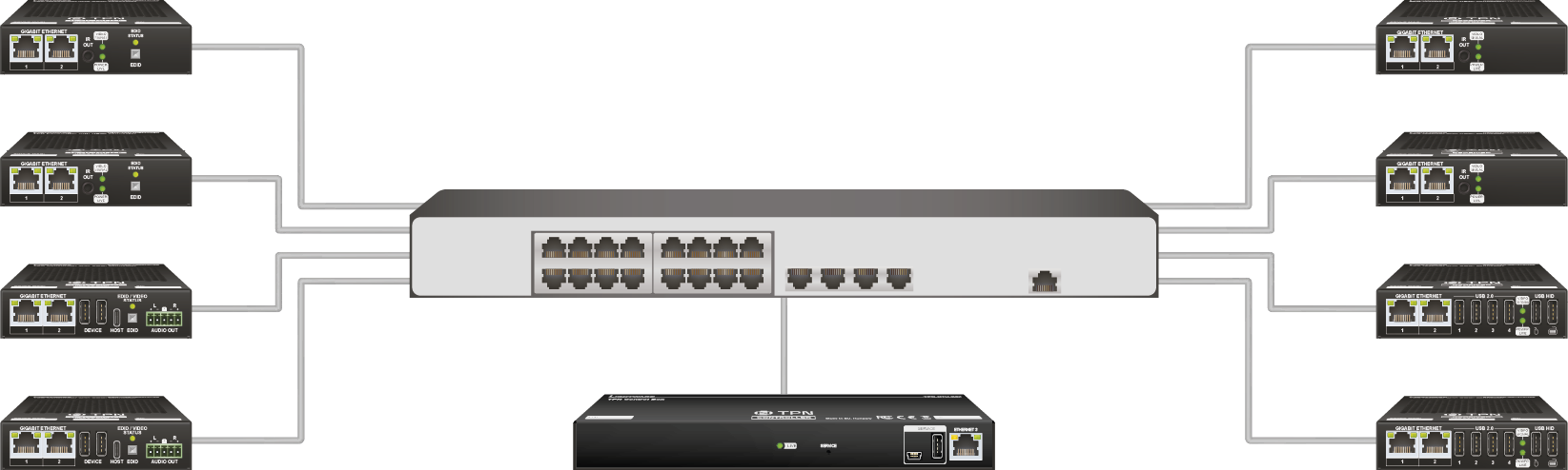
▪Point-Multipoint Connection - Virtual AV matrix with several transmitters, receivers, and a Control Unit (CTU) that controls the AV network.
1.5.1. List of All Features (In Alphabetic Order)

|
4K Support |
|
Up to HDMI 2.0 4K 2160p@60Hz 4:4:4 video input or 4096x2160@60Hz resolution over a 10 Gigabit network with extra low latency. |
|

|
Analog Audio Support |
|
External analog audio signal can be embedded in the video stream at the Encoder side, and can be de-embedded at the Decoder side. |
|

|
Basic IT-security |
|
These entry-level network security improvements help prevent unauthorized access to the Lightware device; HTTPS/WSS support, basic network authentication. |
|

|
Dante® or AES67 Audio De-embedding |
|
The audio of the HDMI signal can be transmitted as a 2-channel Dante® or AES67 source from the D series models over the dedicated RJ45 connector. |
|

|
Dynamic Virtual Matrix |
|
The Control Unit (CTU) can build up a dynamic virtual matrix with any number of transmitters and receivers connected in one network. It displays a traditional crosspoint view of the virtual matrix in the LARA software, also displaying the video streams which can be sorted by unique names for the easy recognition. |
|

|
Ethernet Based Extender |
|
The TPN system is Ethernet based, using 10 GbE, IGMPv2, and IPv4 protocols. |
|

|
GPIO Control Port |
|
7 GPIO pins that operate at TTL digital signal levels and can be controlled with both LW2 and LW3 commands. |
|

|
HDCP 2.3 Compliant |
|
The TPN extenders comply to the HDCP 2.3 standard. HDCP capability on the digital video inputs can be disabled when non-protected content is extended. |
|

|
Local Video Output |
|
User can attach a local monitor to observe the video signal sent through the TPN ports. The resolution and clock frequency are the same as the HDMI inputs, no internal scaling or conversion is applied. |
|

|
Seamless Switching (Clean Cut) |
|
HDMI-TPN-SR and HDMI-OPTN-SR series extenders provide seamless switching (clean cut) technology. Apart from being able to scale the video to the resolution of the connected display, seamless switching provides uninterrupted video output when switching between two streams regardless of the format of the video content. Moreover, switching is instantaneously, thus provides excellent user experience. |
|

|
Lightware Rest API |
|
The switcher can be controlled through standard HTTP(S) requests to ensure the control functions from REST clients or terminal program. |
|

|
Open API |
|
Open-source API technology at the core makes these Lightware products easy to integrate into third-party systems. Every bit of data in Lightware systems is openly available for higher level management and monitoring systems. |
|

|
Modular SFP+ Interface |
|
OPTN series endpoints use standard, certified 10 Gbps SFP+ optical modules, which are plug and play, so they are swappable by the user. |
|

|
Occupancy Sensor Connector |
|
Occupancy sensor connection (with 24V power supply). |
|

|
Point-to-point Connection |
|
Beside the virtual matrix mode the extenders can be connected to each other directly and in this case they operate as a TPX extender pair. |
|

|
Powered by LARA |
|
Future-proof room automation platform for system integrators so they can seamlessly and invisibly support people’s collaboration to get the most out of their virtual or in-person meetings. |
|

|
Remote Power (PoE) |
|
The endpoint devices fulfill the PoE PD standard (according to IEEE 802.3af) which means they can be powered over the Ethernet line by a compatible power source equipment. |
|

|
Scaling the Output Image |
|
Video scaling of -SR series receivers is the process of changing the size of a video frame in order to match the native resolution of a display sink. It involves converting the resolution to a higher or lower format, and also a change in aspect ratio; typically from 4:3 to 16:9. |
|
|
Serial Data Transmission |
|
Transparent serial data transmission is available between the endpoints, both transmitter and receiver devices. |
|

|
USB KVM Extension Powered by Icron |
|
KVM extension for USB HID (Human Interface Devices, e.g. webcamera, keyboard, mouse, presenter) and Mass Storage devices (Flash drive, Hard drive). |
1.5.2. Feature Availability
1.6. Application Diagram
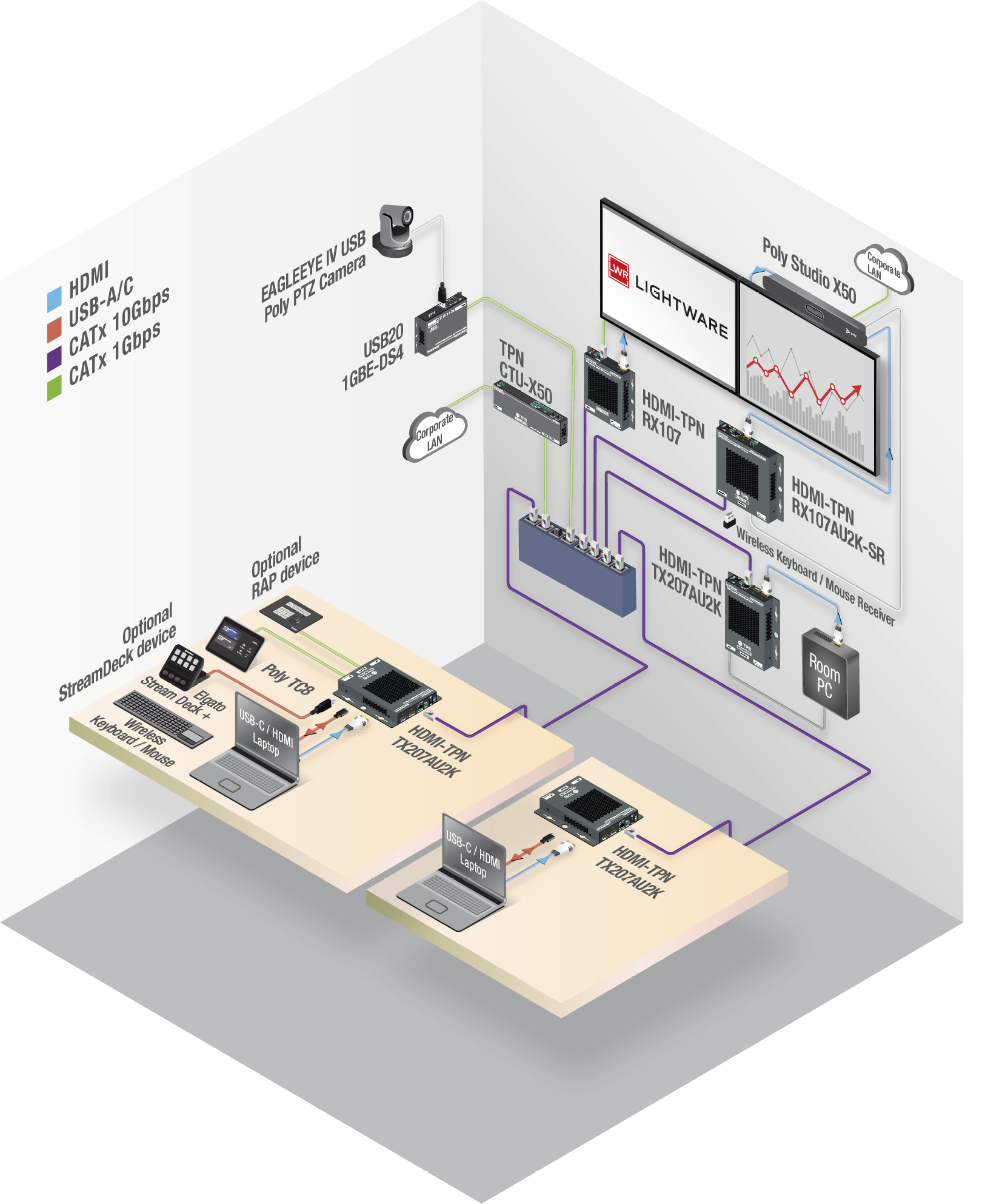
1.6.1. Collaboration Room
1.6.2. Dual Screen Application
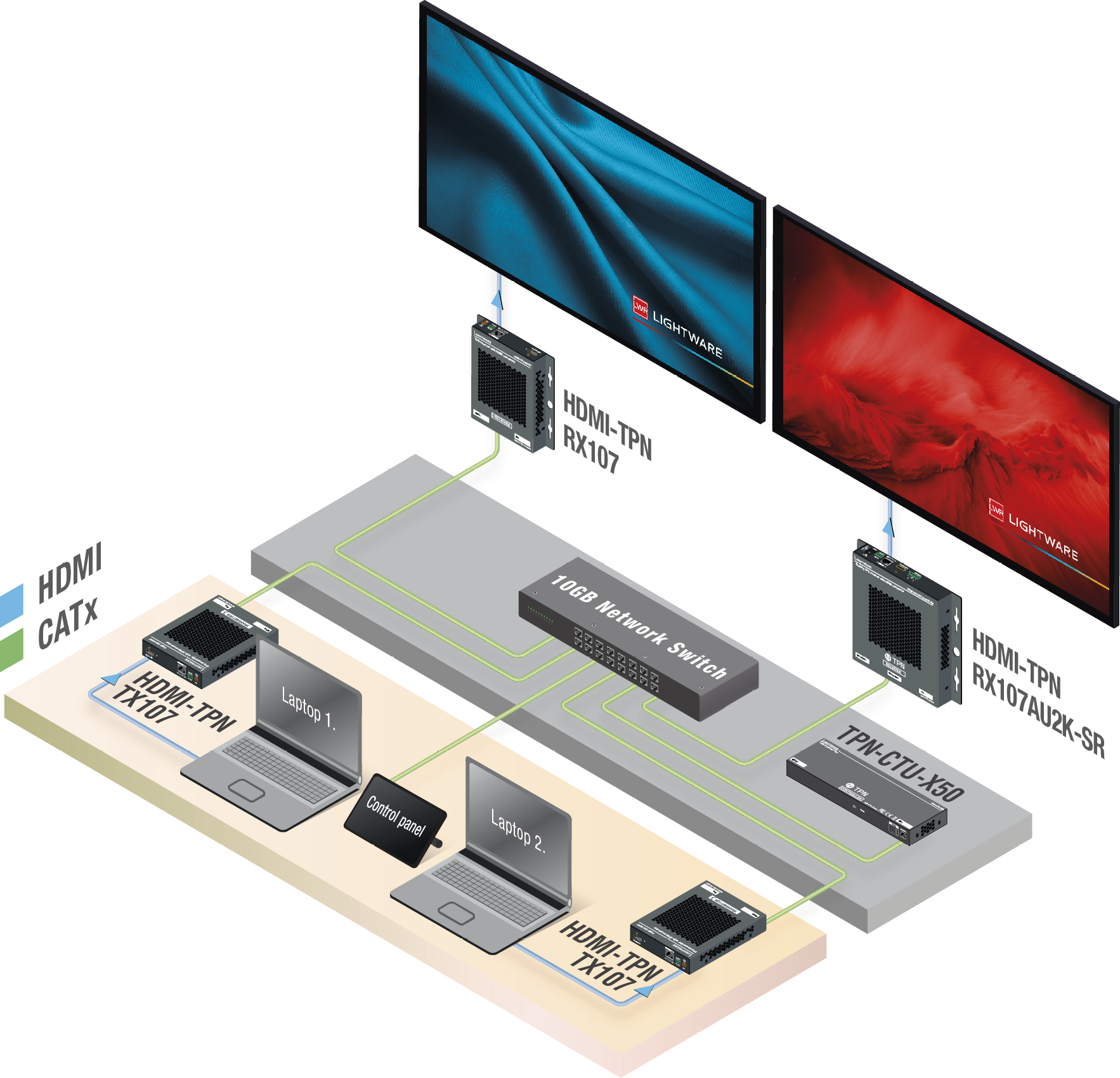
1.6.3. Auditorium
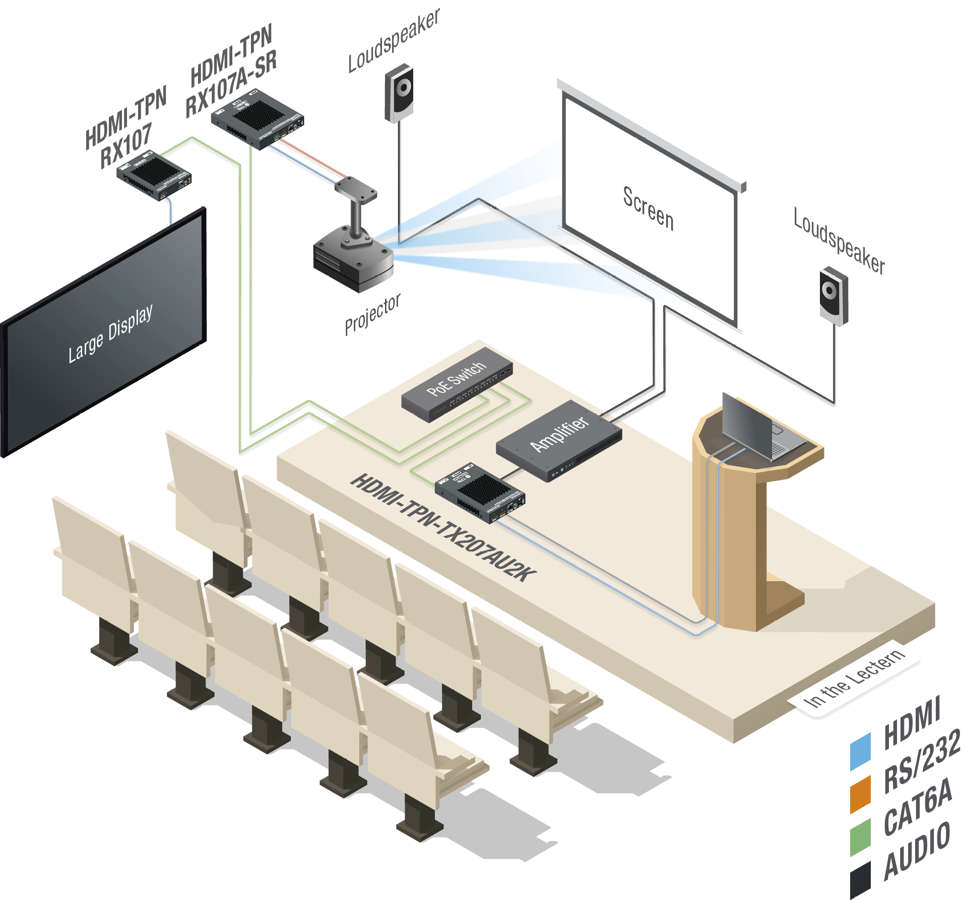
The following sections are about the physical structure of the device, input/ output ports and connectors; software and hardware capabilities:
2.1. Front and Rear View - Transmitters
2.1.1. HDMI-TPN Transmitters
HDMI-TPN-TX107
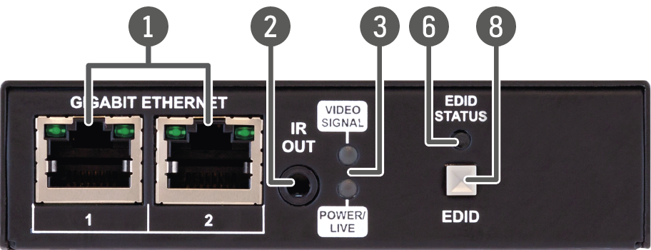
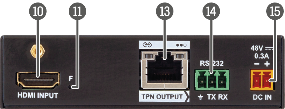
HDMI-TPN-TX207AU2K
|
|
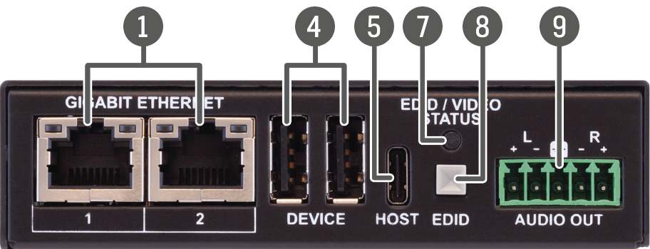
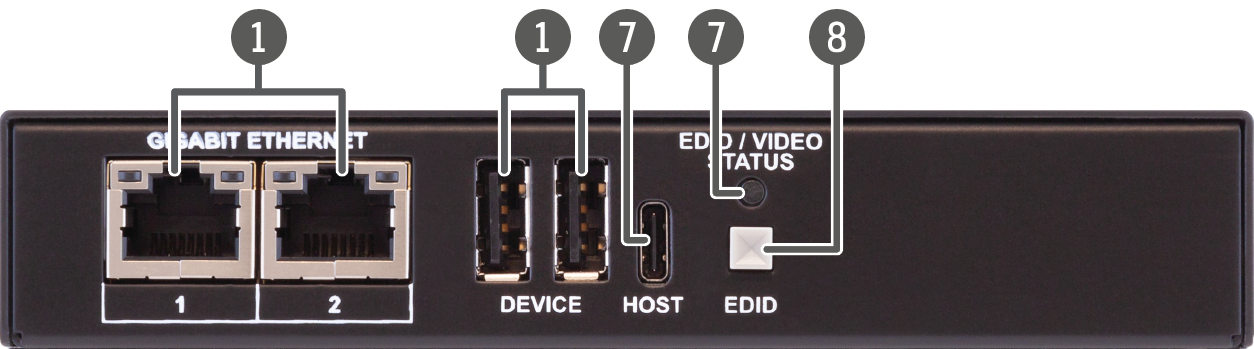
Gigabit Ethernet port |
1GBase-T RJ45 connector for user Ethernet purpose. See more details about the LED operation in the Gigabit Ethernet Status LEDs section. |
|
|
IR out |
TRS (3.5mm jack) output connector for an Infrared emitter unit. |
|
|
Status LEDs |
The LEDs give immediate feedback about the current status of the extender. See the details in the Device Status LEDs - TPN 107 Series (TPN-107 series), Device Status LEDs - TPN AU2K, D, DU2K and SR Series (TPN AU2K and SR series) and the Device Status LEDs - OPTN Series (OPTN) sections. |
|
|
Device USB-A connectors |
USB-A connectors with USB 2.0 support for various types of USB devices. |
|
|
Host USB-C connector |
USB-C connection between the transmitter and the host computer. The port receives USB data only, no AV signal transmission is accepted. It supports USB 2.0 standard only. |
|
|
EDID Status LED |
The EDID LED gives immediate feedback about the current status of the EDID emulation. See the details in the Device Status LEDs - TPN 107 Series section. |
|
|
EDID / Video Status LED |
The EDID LED gives immediate feedback about the current status of the EDID emulation. See the details in the Device Status LEDs - TPN AU2K, D, DU2K and SR Series section. |
|
|
EDID button |
The EDID handling mode depends on the connection type of the extender. See the details in the EDID Button Function section. |
|
|
Audio output |
5-pole Phoenix connector for de-embedding the HDMI audio, which can be transmitted as a 2-channel balanced analog audio signal. |
|
|
HDMI input |
HDMI input port with HDMI 2.0 support for source devices. |
|
|
Factory reset button |
Hidden button for setting the device to factory default values. See more details about it in the Factory Reset (F) Button for Endpoints section. |
|
|
Local HDMI output |
Local HDMI output with the same AV content as the HDMI input. |
|
|
TPN output |
RJ45 connector for SDVoE output signal transmission. See more details about the connector in the USB-A Connectors for Endpoints and the TPN Input/Ouput Status LEDs sections. |
|
|
RS-232 port |
3-pole Phoenix connector for bi-directional serial communication. See more details about the connector in the RS-232 Connector section. |
|
|
48V DC input |
48V DC input connector for local powering. |
|
|
12V DC input |
12V DC input locking connector for local powering. |


WARNING!Always use the supplied power supply. Warranty void if damage occurs due to use of a different power source.
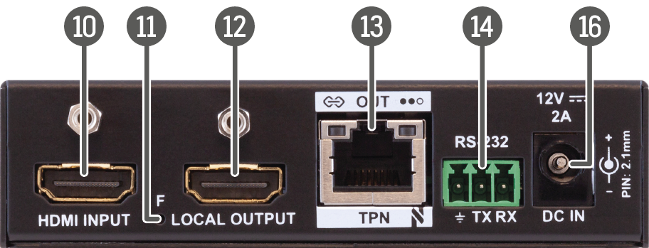
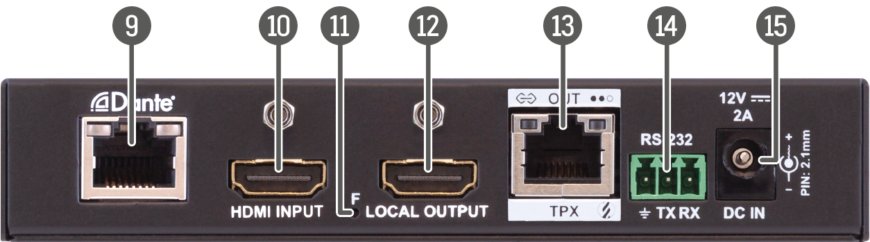
HDMI-TPN-TX107D
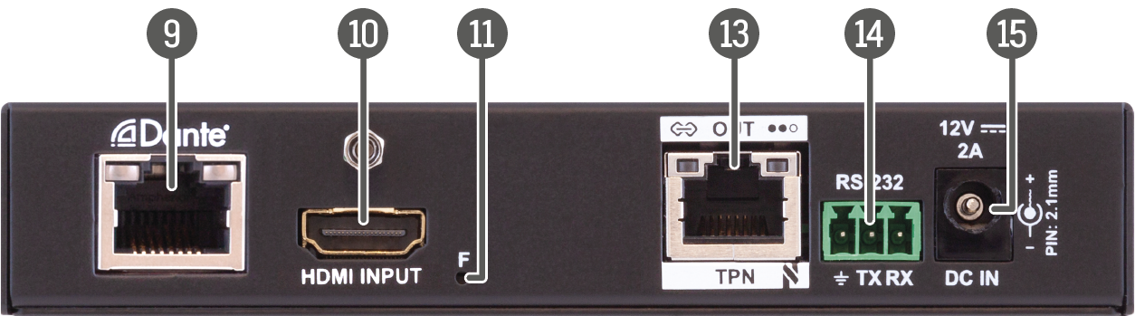
HDMI-TPN-TX207DU2K
|
|
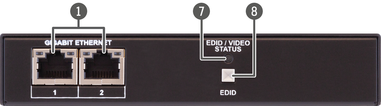
Gigabit Ethernet port |
1GBase-T RJ45 connector for user Ethernet purpose. See more details about the LED operation in the Gigabit Ethernet Status LEDs section. |
|
|
IR out |
TRS (3.5mm jack) output connector for an Infrared emitter unit. |
|
|
Status LEDs |
The LEDs give immediate feedback about the current status of the extender. See the details in the Device Status LEDs - TPN 107 Series (TPN-107 series), Device Status LEDs - TPN AU2K, D, DU2K and SR Series (TPN AU2K and SR series) and the Device Status LEDs - OPTN Series (OPTN) sections. |
|
|
Device USB-A connectors |
USB-A connectors with USB 2.0 support for various types of USB devices. |
|
|
Host USB-C connector |
USB-C connection between the transmitter and the host computer. The port receives USB data only, no AV signal transmission is accepted. It supports USB 2.0 standard only. |
|
|
EDID Status LED |
The EDID LED gives immediate feedback about the current status of the EDID emulation. See the details in the Device Status LEDs - TPN 107 Series section. |
|
|
EDID / Video Status LED |
The EDID LED gives immediate feedback about the current status of the EDID emulation. See the details in the Device Status LEDs - TPN AU2K, D, DU2K and SR Series section. |
|
|
EDID button |
The EDID handling mode depends on the connection type of the extender. See the details in the EDID Button Function section. |
|
|
Dante®/AES67 output |
RJ45 connector for transmitting 2-channel Dante® or AES67 digital audio signal. |
|
|
HDMI input |
HDMI input port with HDMI 2.0 support for source devices. |
|
|
Factory reset button |
Hidden button for setting the device to factory default values. See more details about it in the Factory Reset (F) Button for Endpoints section. |
|
|
Local HDMI output |
Local HDMI output with the same AV content as the HDMI input. |
|
|
TPN output |
RJ45 connector for SDVoE output signal transmission. See more details about the connector in the USB-A Connectors for Endpoints and the TPN Input/Ouput Status LEDs sections. |
|
|
RS-232 port |
3-pole Phoenix connector for bi-directional serial communication. See more details about the connector in the RS-232 Connector section. |
|
|
12V DC input |
12V DC input locking connector for local powering. |
WARNING!Always use the supplied power supply. Warranty void if damage occurs due to use of a different power source.
2.1.2. HDMI-OPTN Transmitters
HDMI-OPTN-TX100A
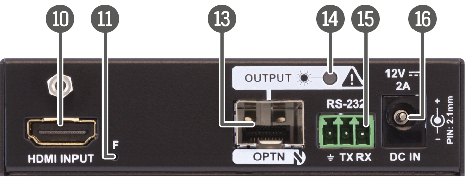
HDMI-OPTN-TX200AU2K
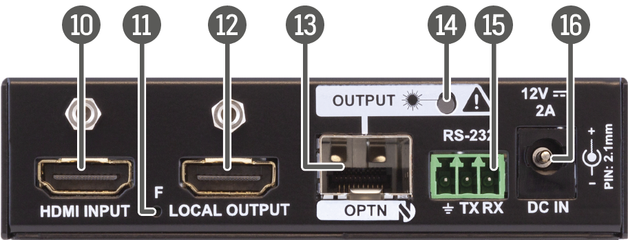
|
|
Gigabit Ethernet port |
1GBase-T RJ45 connector for user Ethernet purpose. See more details about the LED operation in the Gigabit Ethernet Status LEDs section. |
|
|
IR out |
TRS (3.5mm jack) output connector for an Infrared emitter unit. |
|
|
Status LEDs |
The LEDs give immediate feedback about the current status of the extender. See the details in the Device Status LEDs - TPN 107 Series (TPN-107 series), Device Status LEDs - TPN AU2K, D, DU2K and SR Series (TPN AU2K and SR series) and the Device Status LEDs - OPTN Series (OPTN) sections. |
|
|
Device USB-A connectors |
USB-A connectors with USB 2.0 support for various types of USB devices. |
|
|
Host USB-C connector |
USB-C connection between the transmitter and the host computer. The port receives USB data only, no AV signal transmission is accepted. It supports USB 2.0 standard only. |
|
|
EDID Status LED |
The EDID LED gives immediate feedback about the current status of the EDID emulation. See the details in the Device Status LEDs - TPN 107 Series section. |
|
|
EDID / Video Status LED |
The EDID LED gives immediate feedback about the current status of the EDID emulation. See the details in the Device Status LEDs - TPN AU2K, D, DU2K and SR Series section. |
|
|
EDID button |
The EDID handling mode depends on the connection type of the extender. See the details in the EDID Button Function section. |
|
|
Audio output |
5-pole Phoenix connector for de-embedding the HDMI audio, which can be transmitted as a 2-channel balanced analog audio signal. |
|
|
HDMI input |
HDMI input port with HDMI 2.0 support for source devices. |
|
|
Factory reset button |
Hidden button for setting the device to factory default values. See more details about it in the Factory Reset (F) Button for Endpoints section. |
|
|
Local HDMI output |
Local HDMI output with the same AV content as the HDMI input. |
|
|
SFP+ port slot for OPTN output connection |
Optical output port slot for a 10 GbE SFP+ module or a DAC cable. Port can be used for either singlemode or multimode optical connection. |
|
|
OPTN output link LED |
The LED gives immediate feedback about the current status of the optical connection. See the details in the Device Status LEDs - OPTN Series section. |
|
|
RS-232 port |
3-pole Phoenix connector for bi-directional serial communication. See more details about the connector in the RS-232 Connector section. |
|
|
12V DC input |
12V DC input locking connector for local powering. |


WARNING!Always use the supplied power supply. Warranty void if damage occurs due to use of a different power source.
2.2. Front and Rear View - Receivers
2.2.1. TPN Non-scaling Receivers
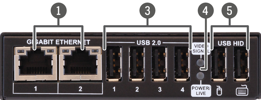
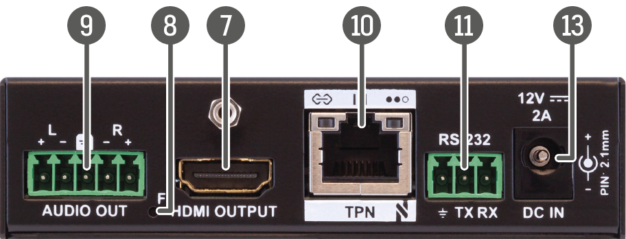
HDMI-TPN-RX107
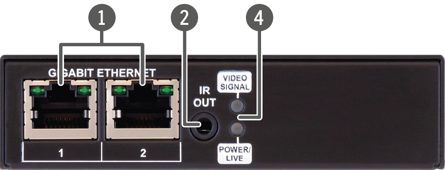
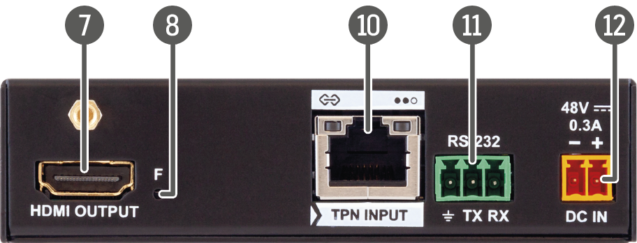
HDMI-TPN-RX107AU2K
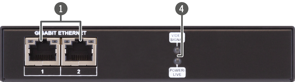
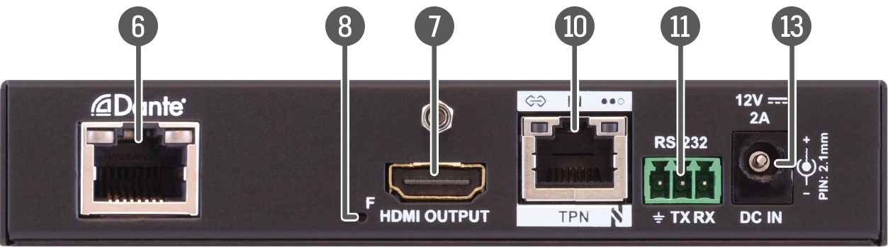
HDMI-TPN-RX107D
|
|
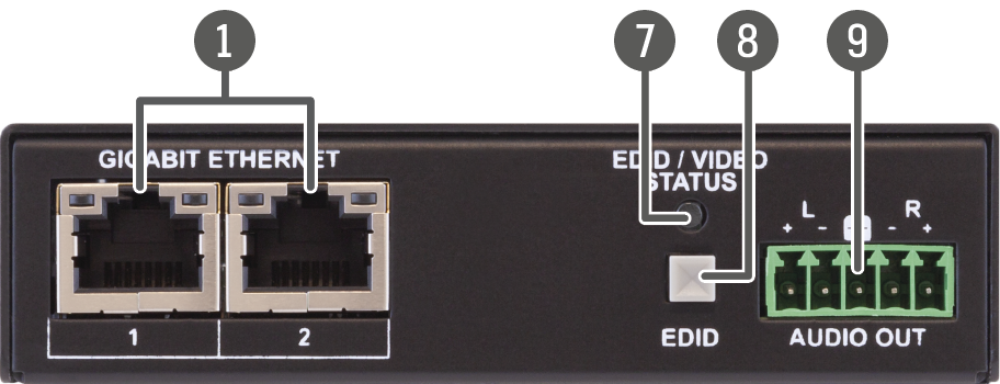
Gigabit Ethernet port |
1GBase-T RJ45 connector for user Ethernet purpose. See more details about the LED operation in the Gigabit Ethernet Status LEDs section. |
|
|
IR out |
TRS (3.5mm jack) output connector for an Infrared emitter unit. |
|
|
USB 2.0 connectors |
USB-A connectors with USB 2.0 support for various types of USB devices (e.g. webcam, microphone, external storage, etc). The signal is transmitted to the transmitter over the TPN link. |
|
|
Status LEDs |
The LEDs give immediate feedback about the current status of the extender. See the details in the Device Status LEDs - TPN 107 Series (TPN-107 series), Device Status LEDs - TPN AU2K, D, DU2K and SR Series (TPN AU2K and SR series) and the Device Status LEDs - OPTN Series (OPTN) sections. |
|
|
USB HID connectors |
USB K+M ports for HID-compatible devices (preferably keyboard and mouse). The signal is transmitted to the transmitter over the TPN link. |
|
|
Dante®/AES67 output |
RJ45 connector for transmitting 2-channel Dante® or AES67 digital audio signal. |
|
|
HDMI output |
HDMI output port with HDMI 2.0 support for sink devices. |
|
|
Factory reset button |
Hidden button for setting the device to factory default values. See more details about it in the Factory Reset (F) Button for Endpoints section. |
|
|
Audio output |
5-pole Phoenix connector for de-embedding the HDMI audio, which can be transmitted as a 2-channel balanced analog audio signal. |
|
|
TPN input |
RJ45 connector for SDVoE input signal. See more details about the connector in the USB-A Connectors for Endpoints and the TPN Input/Ouput Status LEDs sections. |
|
|
RS-232 port |
3-pole Phoenix connector for bi-directional serial communication. See more details about the connector in the RS-232 Connector section. |
|
|
48V DC input |
48V DC input connector for local powering. |
|
|
12V DC input |
12V DC input locking connector for local powering. |
WARNING!Always use the supplied power supply. Warranty void if damage occurs due to use of a different power source.
2.2.2. OPTN Non-scaling Receivers
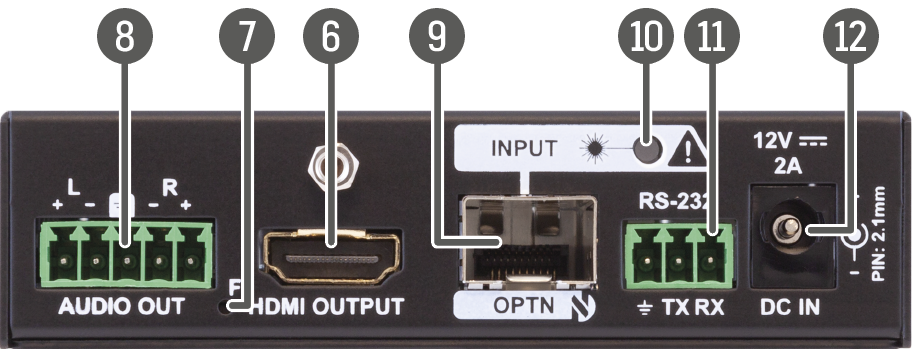
HDMI-OPTN-RX100A
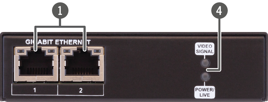
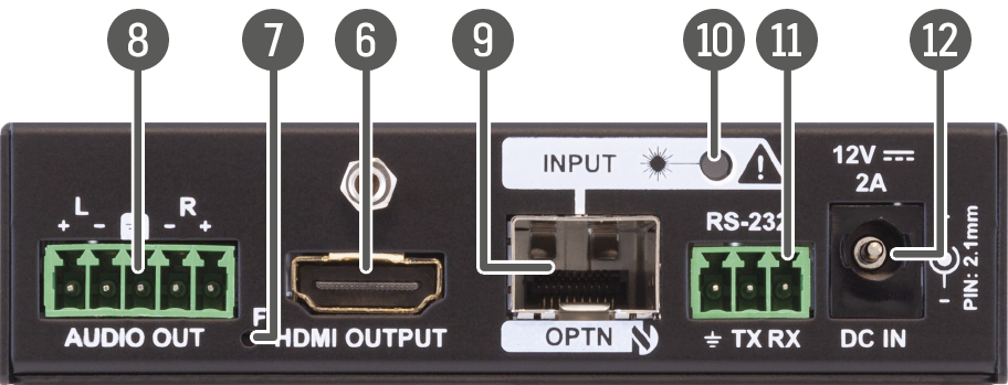
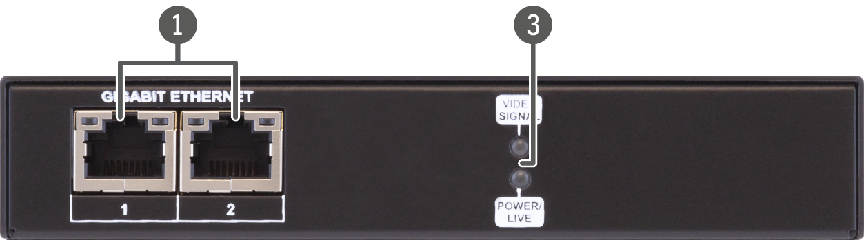
HDMI-OPTN-RX100AU2K
|
|
Gigabit Ethernet port |
1GBase-T RJ45 connector for user Ethernet purpose. See more details about the LED operation in the Gigabit Ethernet Status LEDs section. |
|
|
IR out |
TRS (3.5mm jack) output connector for an Infrared emitter unit. |
|
|
USB 2.0 connectors |
USB-A connectors with USB 2.0 support for various types of USB devices (e.g. webcam, microphone, external storage, etc). The signal is transmitted to the transmitter over the TPN link. |
|
|
Status LEDs |
The LEDs give immediate feedback about the current status of the extender. See the details in the Device Status LEDs - TPN 107 Series (TPN-107 series), Device Status LEDs - TPN AU2K, D, DU2K and SR Series (TPN AU2K and SR series) and the Device Status LEDs - OPTN Series (OPTN) sections. |
|
|
USB HID connectors |
USB K+M ports for HID-compatible devices (preferably keyboard and mouse). The signal is transmitted to the transmitter over the TPN link. |
|
|
HDMI output |
HDMI output port with HDMI 2.0 support for sink devices. |
|
|
Factory reset button |
Hidden button for setting the device to factory default values. See more details about it in the Factory Reset (F) Button for Endpoints section. |
|
|
Audio output |
5-pole Phoenix connector for de-embedding the HDMI audio, which can be transmitted as a 2-channel balanced analog audio signal. |
|
|
SFP+ port slot for OPTN input connection |
Optical input port slot for a 10 GbE SFP+ module or a DAC cable. The port can be used for either singlemode or multimode optical connection. |
|
|
OPTN input link LED |
The LED gives immediate feedback about the current status of the optical connection. See the details in the Device Status LEDs - OPTN Series section. |
|
|
RS-232 port |
3-pole Phoenix connector for bi-directional serial communication. See more details about the connector in the RS-232 Connector section. |
|
|
12V DC input |
12V DC input locking connector for local powering. |
WARNING!Always use the supplied power supply. Warranty void if damage occurs due to use of a different power source.
2.2.3. TPN Scaling Receivers
HDMI-TPN-RX107A-SR
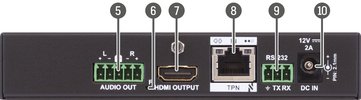
HDMI-TPN-RX107AU2K-SR
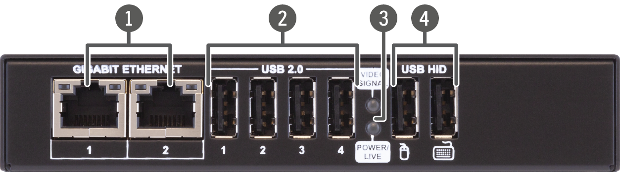
|
|
Gigabit Ethernet port |
1GBase-T RJ45 connector for user Ethernet purpose. See more details about the LED operation in the Gigabit Ethernet Status LEDs section. |
|
|
USB 2.0 connectors |
USB-A connectors with USB 2.0 support for various types of USB devices (e.g. webcam, microphone, external storage, etc). The signal is transmitted to the transmitter over the TPN link. |
|
|
Status LEDs |
The LEDs give immediate feedback about the current status of the extender. See the details in the Device Status LEDs - TPN AU2K, D, DU2K and SR Series section. |
|
|
USB HID connectors |
USB K+M ports for HID-compatible devices (preferably keyboard and mouse). The signal is transmitted to the transmitter over the TPN link. |
|
|
Audio output |
5-pole Phoenix connector for de-embedding the HDMI audio, which can be transmitted as a 2-channel balanced analog audio signal. |
|
|
Factory reset button |
Hidden button for setting the device to factory default values. See more details about it in the Factory Reset (F) Button for Endpoints section. |
|
|
HDMI output |
HDMI output port with HDMI 2.0 support for sink devices. |
|
|
TPN input |
RJ45 connector for SDVoE input signal. See more details about the connector in the USB-A Connectors for Endpoints and the TPN Input/Ouput Status LEDs sections. |
|
|
RS-232 port |
3-pole Phoenix connector for bi-directional serial communication. See more details about the connector in the RS-232 Connector section. |
|
|
12V DC input |
12V DC input locking connector for local powering. |
WARNING!Always use the supplied power supply. Warranty void if damage occurs due to use of a different power source.
HDMI-TPN-RX107D-SR
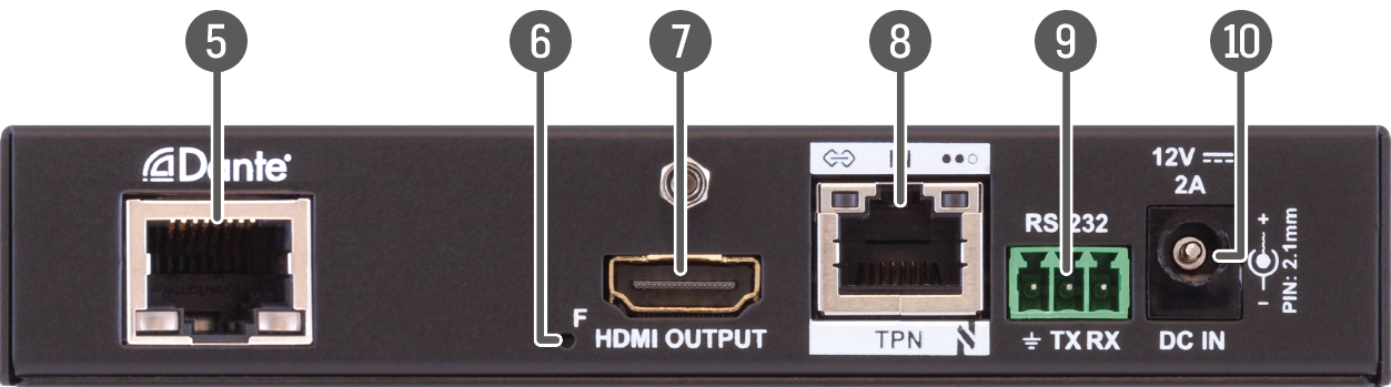
HDMI-TPN-RX107DU2K-SR
|
|
Gigabit Ethernet port |
1GBase-T RJ45 connector for user Ethernet purpose. See more details about the LED operation in the Gigabit Ethernet Status LEDs section. |
|
|
USB 2.0 connectors |
USB-A connectors with USB 2.0 support for various types of USB devices (e.g. webcam, microphone, external storage, etc). The signal is transmitted to the transmitter over the TPN link. |
|
|
Status LEDs |
The LEDs give immediate feedback about the current status of the extender. See the details in the Device Status LEDs - TPN AU2K, D, DU2K and SR Series section. |
|
|
USB HID connectors |
USB K+M ports for HID-compatible devices (preferably keyboard and mouse). The signal is transmitted to the transmitter over the TPN link. |
|
|
Dante®/AES67 output |
RJ45 connector for transmitting 2-channel Dante® or AES67 digital audio signal. |
|
|
Factory reset button |
Hidden button for setting the device to factory default values. See more details about it in the Factory Reset (F) Button for Endpoints section. |
|
|
HDMI output |
HDMI output port with HDMI 2.0 support for sink devices. |
|
|
TPN input |
RJ45 connector for SDVoE input signal. See more details about the connector in the USB-A Connectors for Endpoints and the TPN Input/Ouput Status LEDs sections. |
|
|
RS-232 port |
3-pole Phoenix connector for bi-directional serial communication. See more details about the connector in the RS-232 Connector section. |
|
|
12V DC input |
12V DC input locking connector for local powering. |
WARNING!Always use the supplied power supply. Warranty void if damage occurs due to use of a different power source.
2.2.4. OPTN Scaling Receivers
HDMI-OPTN-RX100A-SR
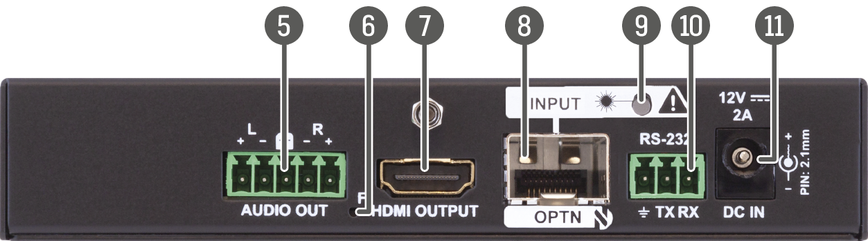
HDMI-OPTN-RX100AU2K-SR
|
|
Gigabit Ethernet port |
1GBase-T RJ45 connector for user Ethernet purpose. See more details about the LED operation in the Gigabit Ethernet Status LEDs section. |
|
|
USB 2.0 connectors |
USB-A connectors with USB 2.0 support for various types of USB devices (e.g. webcam, microphone, external storage, etc). The signal is transmitted to the transmitter over the TPN link. |
|
|
Status LEDs |
The LEDs give immediate feedback about the current status of the extender. See the details in the Device Status LEDs - OPTN Series section. |
|
|
USB HID connectors |
USB K+M ports for HID-compatible devices (preferably keyboard and mouse). The signal is transmitted to the transmitter over the TPN link. |
|
|
Audio output |
5-pole Phoenix connector for de-embedding the HDMI audio, which can be transmitted as a 2-channel balanced analog audio signal. |
|
|
Factory reset button |
Hidden button for setting the device to factory default values. See more details about it in the Factory Reset (F) Button for Endpoints section. |
|
|
HDMI output |
HDMI output port with HDMI 2.0 support for sink devices. |
|
|
SFP+ port slot for OPTN input connection |
Optical input port slot for a 10 GbE SFP+ module or a DAC cable. The port can be used for either singlemode or multimode optical connection. |
|
|
OPTN input link LED |
The LED gives immediate feedback about the current status of the optical connection. See the details in the Device Status LEDs - OPTN Series section. |
|
|
RS-232 port |
3-pole Phoenix connector for bi-directional serial communication. See more details about the connector in the RS-232 Connector section. |
|
|
12V DC input |
12V DC input locking connector for local powering. |
WARNING!Always use the supplied power supply. Warranty void if damage occurs due to use of a different power source.
2.3. Front and Rear View - TPN-CTU-X50
Front View

Rear View

|
|
LIVE LED |
The LED gives immediate feedback about the current status of the CTU. See the details in the Device Status LED - TPN-CTU-X50 section. |
|
|
Service button |
Hidden button for setting the device to factory default values. See more details about it in the Factory Reset (Service) Button for CTU section. |
|
|
USB mini-B port |
Reserved for service functions. |
|
|
USB-A port |
Reserved for future development. |
|
|
Configurable Ethernet ports |
RJ45 connectors for configurable 100Base-T Ethernet communication. See more details about the LED operation in the Gigabit Ethernet Status LEDs section. |
|
|
GPIO |
8-pole Phoenix® connector for configurable general purpose. Max. input/ output voltage is 5V, see the details in the GPIO - General Purpose Input/Output Ports section. WARNING! The port is NOT compatible with the OCS connector. |
|
|
OCS sensor connector |
3-pole Phoenix® connector (male) for connecting an occupancy sensor. The port provides 24V output voltage (50mA), see the details in the OCS Connector section. WARNING! The port is NOT compatible with the GPIO connector. |
|
|
RS-232 connectors |
2 pcs 3-pole Phoenix® connectors for bi-directional RS-232 communication. See more details about the connector in the RS-232 Connector section. |
|
|
5V DC input |
5V DC input connector for local powering. |
WARNING!Always use the supplied power supply. Warranty void if damage occurs due to use of a different power source.
2.4. Front and Rear Panel LEDs
2.4.1. Device Status LEDs - TPN 107 Series
Affected models:
▪HDMI-TPN-TX107
▪HDMI-TPN-RX107
|
POWER/LIVE |
Transmitter / Receiver |
||

|
off |
Device is not powered. |
|

|
blinking between 50% and 100% brightness (green) |
Device is powered on and operational. |
|
|
VIDEO SIGNAL |
Transmitter / Receiver |
||

|
off |
No video signal present on the HDMI input (TX) or HDMI output (RX) port. |
|

|
on (green) |
Video signal is present on the HDMI input (TX) or HDMI output (RX) port. |
|
|
EDID STATUS |
Transmitter |
||

|
on (green) |
Default EDID is emulated on the HDMI input port. |
|

|
on (yellow) |
User EDID is emulated on the HDMI input port. |
|

|
blinking (red) |
Error occured during the EDID emulation. It may be caused by: ▪EDID emulation cannot be set correctly. ▪Device cannot apply user EDID emulation. |
|
2.4.2. Device Status LEDs - TPN AU2K, D, DU2K and SR Series
Affected models:
▪HDMI-TPN-TX207AU2K
▪HDMI-TPN-TX107D
▪HDMI-TPN-TX207DU2K
▪HDMI-TPN-RX107AU2K
▪HDMI-TPN-RX107A-SR
▪HDMI-TPN-RX107D-SR
▪HDMI-TPN-RX107AU2K-SR
▪HDMI-TPN-RX107DU2K-SR
|
EDID / VIDEO STATUS |
Transmitter |
||
|
|
off |
Device is not powered. |
|

|
blinking (green or yellow) |
No video signal present on the HDMI input port. |
|
|
|
on (green) |
Default EDID is emulated on the HDMI input port. |
|
|
|
on (yellow) |
User EDID is emulated on the HDMI input port. |
|

|
blinking (red) |
Error occured during the EDID emulation. It may be caused by: ▪EDID emulation cannot be set correctly. ▪Device cannot apply user EDID emulation. |
|
|
POWER/LIVE |
Receiver |
||
|
|
off |
Device is not powered. |
|
|
|
blinking between 50% and 100% brightness (green) |
Device is powered on and operational. |
|
|
VIDEO SIGNAL |
Receiver |
||

|
off |
No video signal present on the HDMI output port. |
|

|
on (green) |
Video signal is present on the HDMI output port. |
|
2.4.3. Device Status LEDs - OPTN Series
Affected models:
▪HDMI-OPTN-TX100A
▪HDMI-OPTN-TX200AU2K
▪HDMI-OPTN-RX100A
▪HDMI-OPTN-RX100AU2K
▪HDMI-OPTN-RX100A-SR
▪HDMI-OPTN-RX100AU2K-SR
|
EDID / VIDEO STATUS |
Transmitter |
||
|
|
off |
Device is not powered. |
|
|
|
blinking (green or yellow) |
No video signal present on the HDMI input port. |
|
|
|
on (green) |
Default EDID is emulated on the HDMI input port. |
|
|
|
on (yellow) |
User EDID is emulated on the HDMI input port. |
|
|
|
blinking (red) |
Error occured during the EDID emulation. It may be caused by: ▪EDID emulation cannot be set correctly. ▪Device cannot apply user EDID emulation. |
|
|
POWER/LIVE |
Receiver |
||
|
|
off |
Device is not powered. |
|
|
|
blinking between 50% and 100% brightness (green) |
Device is powered on and operational. |
|
|
VIDEO SIGNAL |
Receiver |
||
|
|
off |
No video signal present on the HDMI output port. |
|
|
|
on (green) |
Video signal is present on the HDMI output port. |
|
|
OPTN INPUT / OUTPUT LINK LED |
Transmitter / Receiver |
||
|
|
off |
Device is not powered or SFP+ transceiver module is not installed. |
|

|
on (red) |
Device might emit laser radiation. |
|
|
|
on (green) |
Optical link established. |
|
2.4.4. Device Status LED - TPN-CTU-X50
Affected model:
▪TPN-CTU-X50
|
LIVE LED |
CTU |
||

|
off |
Device is not powered. |
|

|
blinking (green) |
Device is powered on and operational. |
|
2.4.5. TPN Input/Ouput Status LEDs
Affected models:
▪HDMI-TPN-TX107
▪HDMI-TPN-TX107D
▪HDMI-TPN-TX207DU2K
▪HDMI-TPN-RX107
▪HDMI-TPN-RX107D
▪HDMI-TPN-TX207AU2K
▪HDMI-TPN-RX107AU2K
▪HDMI-TPN-RX107D-SR
▪HDMI-TPN-RX107AU2K-SR
▪HDMI-TPN-RX107DU2K-SR
|
TPN INPUT/OUTPUT |

|
Transmitter / Receiver |
|

|
off |
No connection is established between the transmitter and the receiver units. |
|

|
on (green) |
Connection is established with 10G / 5G / 2.5G bandwith. |
|
|
TPN INPUT/OUTPUT |

|
Transmitter / Receiver |
|

|
off |
No data transmission on the port. |
|

|
blinking (green) |
Data transmission is active. |
|
2.4.6. Gigabit Ethernet Status LEDs
Affected models:
▪HDMI-TPN-TX107
▪HDMI-TPN-TX107D
▪HDMI-TPN-TX207DU2K
▪HDMI-TPN-RX107
▪HDMI-TPN-RX107D
▪HDMI-TPN-TX207AU2K
▪HDMI-TPN-RX107AU2K
▪HDMI-TPN-RX107A-SR
▪HDMI-TPN-RX107D-SR
▪HDMI-TPN-RX107AU2K-SR
▪HDMI-TPN-RX107DU2K-SR
▪HDMI-OPTN-TX100A
▪HDMI-OPTN-TX200AU2K
▪HDMI-OPTN-RX100A
▪HDMI-OPTN-RX100AU2K
▪HDMI-OPTN-RX100A-SR
▪HDMI-OPTN-RX100AU2K-SR
▪TPN-CTU-X50
|
GIGABIT ETHERNET - LEFT LED |
Transmitter / Receiver / CTU |
||
|
|
on (green) |
Connection is established with 100Mbps bandwith. |
|

|
blinking (green) |
Data transmission is active. |
|
|
GIGABIT ETHERNET - RIGHT LED |
Transmitter / Receiver / CTU |
||
|
|
on (green) |
Connection is established with 1Gbps bandwith. |
|
|
|
blinking (green) |
Data transmission is active. |
|
2.4.7. Dante Connector LEDs
Version 1
Affected models:
▪HDMI-TPN-TX107D
▪HDMI-TPN-TX207DU2K
▪HDMI-TPN-RX107D
|
LED state |
Left LED |
Right LED |
Function |
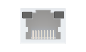
|
Off |
Off |
No power |
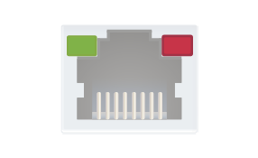
|
Solid green |
Solid red |
Dante is booting |
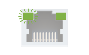
|
Blinking green |
Solid green |
Slave with sync (normal operation) |
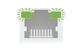
|
Blinking green |
Blinking green |
Clock master (normal operation) |
|
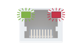
Blinking green |
Blinking red |
Acquiring clock sync (normal operation) |
|
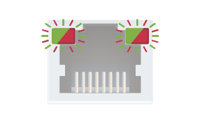
Alternating red/green |
Alternating red/green |
Identify (blinking for 6 seconds) |
|
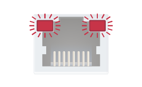
Blinking red |
Blinking red |
Dante fail safe |
|
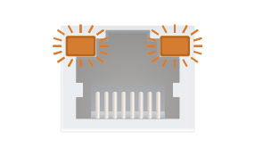
Blinking amber |
Blinking amber |
Device is upgrading |
Version 2
Affected models:
▪HDMI-TPN-RX107D-SR
▪HDMI-TPN-RX107DU2K-SR
|
LED state |
Left LED |
Right LED |
Function |
|
|
Off |
Off |
No power |
|
|
Solid green |
Solid red |
Dante is booting |
|
|
Blinking green |
Solid green |
Slave with sync (normal operation) |
|
|
Blinking green |
Blinking green |
Clock master (normal operation) |
|
|
Blinking green |
Blinking red |
Acquiring clock sync (normal operation) |
|
|
Alternating red/green |
Alternating red/green |
Identify (blinking for 6 seconds) |
|
|
Blinking red |
Blinking red |
Dante fail safe |
|
|
Blinking amber |
Blinking amber |
Device is upgrading |
DIFFERENCE:The TPN/OPTN series transmitters are the only ones built with EDID button.
The EDID handling mode depends on the connection type of the extender. #edid
Point-to-point connection (TPX mode)
Two EDID emulation modes can be selected with the EDID button: Learned and Transparent.
▪Short press: switch between transparent and stored user EDID.
▪Long press: learn and store EDID from the output of the receiver.
Point-multipoint connection (TPN mode)
Two EDID emulation modes can be selected with the button: Default and User.
▪Short press: switch between default and stored user EDID.
2.5.2. Factory Reset (F) Button for Endpoints
DIFFERENCE:The following method is related to the TPN/OPTN series endpoint devices only.
To restore factory default values, do the following steps: #factory
Step 1.Prepare a thin and long tool (e.g. a pen, toothpick, piece of wire, etc).
Step 2.Make sure the device is powered on and operational.
Step 3.Press and keep pressing the hidden F button using the tool for 3 seconds. After 3 seconds the LEDs start blinking faster.
Step 4.The LEDs get dark, the device restores the factory default settings and reboots.
2.5.3. Factory Reset (Service) Button for CTU
DIFFERENCE:The following method is related to the TPN-CTU-X50 control unit only.
To restore factory default values, do the following steps: #factory
Step 1.Prepare a thin and long tool (e.g. a pen, toothpick, piece of wire, etc).
Step 2.Make sure the device is powered on and operational.
Step 3.Press and keep pressing the hidden SERVICE button using the tool for 10 seconds.
Step 4.After 10 seconds the LEDs start blinking faster; release the button and press it 3 times again quickly (within 3 seconds).
Step 5.The LEDs get dark, the device restores the factory default settings and reboots.
Factory default settings are listed in the Factory Default Settings section.
This chapter is about the installation of the device and connecting to other appliances, also presenting also the mounting options and further assembly steps:
3.1. Mounting Options - Compatibility Table
The following table summarizes the compatiblity of the TPN series devices with the mounting accessories offered by Lightware. The number in the brackets means how many same-size devices can be assembled to the mounting plate. The dimensions are in mm. The following accessories can be ordered separately, please contact sales@lightware.com for the details.
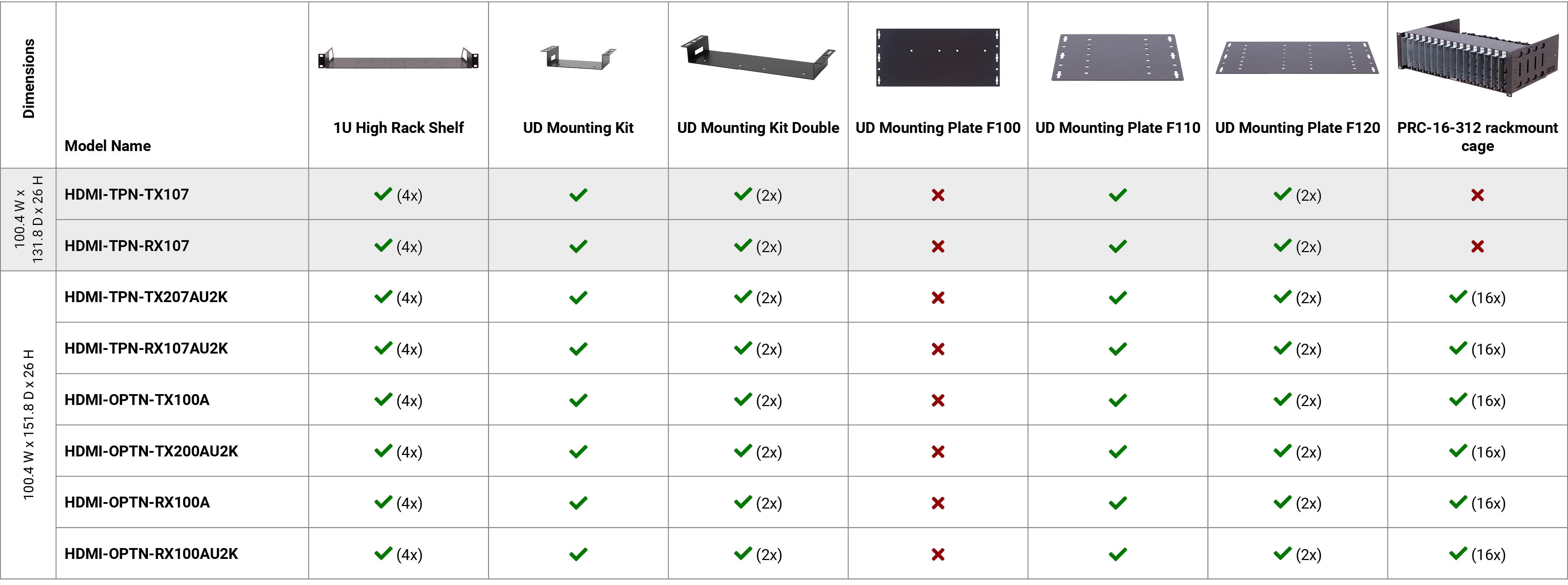
WARNING!Pay attention to the ventilation holes when designing the system. Top and side ventilation holes must not be covered.
INFO:See the details about the assembly steps for each models in our Mounting Assembly Guide downloaded from the website.
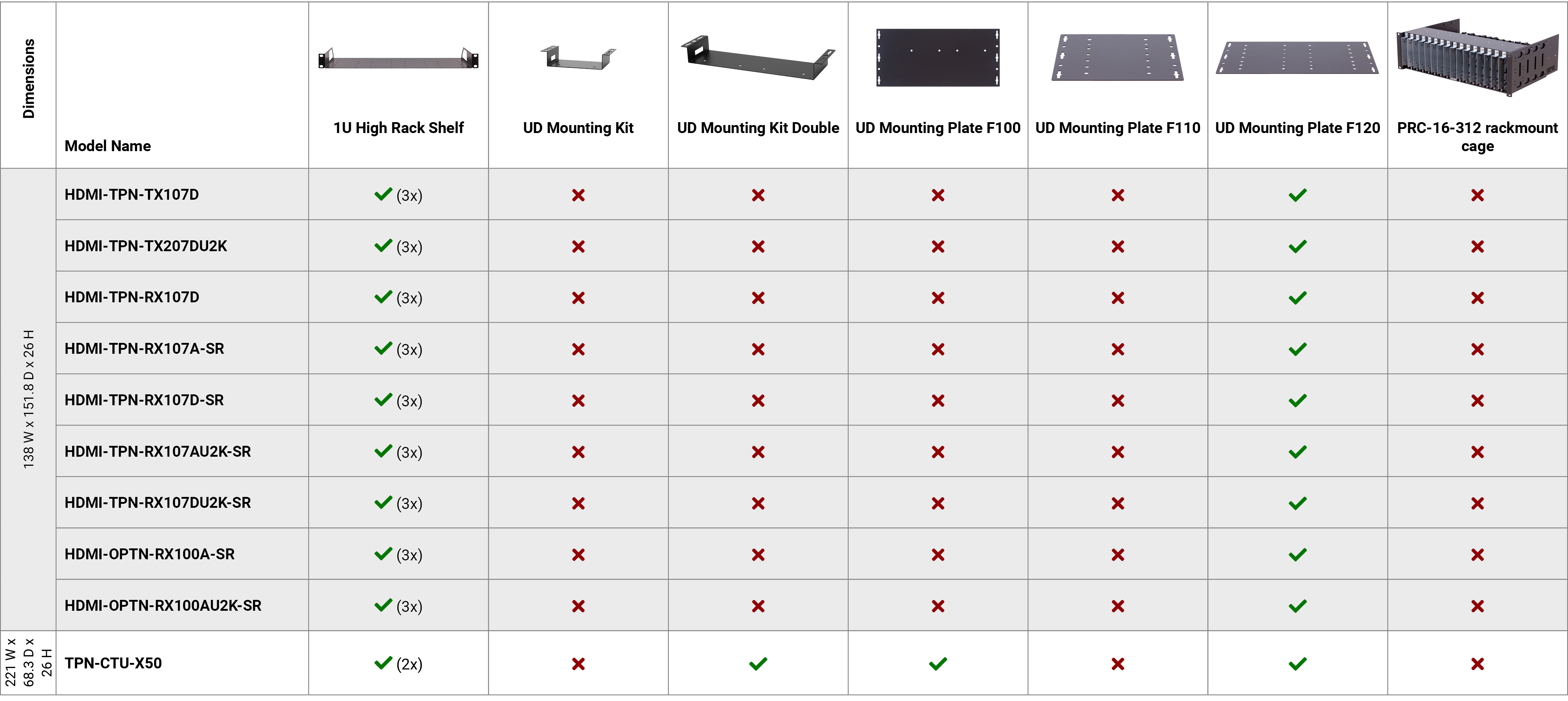
WARNING!Pay attention to the ventilation holes when designing the system. Top and side ventilation holes must not be covered.
INFO:See the details about the assembly steps for each models in our Mounting Assembly Guide downloaded from the website.
3.2.1. 48V DC Input Connector
HDMI-TPN-TX107 and RX107 extenders are built with 2-pole Phoenix connector for 48V DC 1A power connection.

2-pole Phoenix connector and plug pin assignments
WARNING!Always use the supplied 48V power adaptor. Warranty void if damage occurs due to use of a different power source.
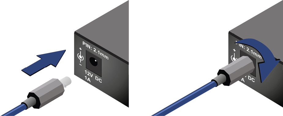
Locking DC connector
Do not forget to turn the plug counterclockwise before disconnecting the power adaptor.
WARNING!Always use the supplied 12V power adaptor. Warranty void if damage occurs due to use of a different power source.
3.2.3. DC 5V Input Connector
The TPN-CTU-X50 is built with 2-pole Phoenix connector for 5V DC 3A power connection.

2-pole Phoenix connector and plug pin assignments
WARNING!Always use the supplied 5V power adaptor. Warranty void if damage occurs due to use of a different power source.
3.2.4. HDMI Input and Output Ports
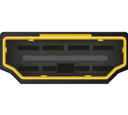
The HDMI-TPN series endpoint devices are assembled with standard 19-pole HDMI 2.0 connectors with screw lock for inputs and outputs. Always use high quality HDMI cables for connecting sources and displays.
5-pole Phoenix connector is used for balanced analog audio output. Unbalanced audio device can be connected as well. See more details about the balanced and unbalanced output port wiring in the Cable Wiring Guide section.
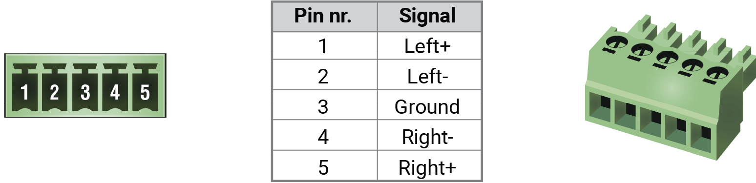
Analog audio connector and plug pin assignments
Compatible Plug Type
Phoenix® Combicon series (3.5mm pitch, 5-pole), type: MC 1.5/5-ST-3.5.
3.2.6. USB-A Connectors for Endpoints
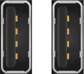
AU2K series endpoint models provide USB-A connectors for supporting KVM functionality supporting HDMI 2.0 standard.
3.2.7. USB Type-C for Endpoints

HDMI-TPN-TX207AU2K endpoint model provides a USB Type-C connector for USB connection between the transmitter and the host computer.
ATTENTION!The port receives USB data only, no AV signal transmission is accepted. It supports USB 2.0 standard only.
3.2.8. USB Connectors for CTU

USB Type-A
Reserved for future developments.
USB Mini B-Type
The connector is used for service functions.
3.2.9. Ethernet Connectors
ATTENTION!Before the installation of the Ethernet connections please read our CATx cable recommendations in the CATx Cable Diagnostics for TPN Endpoints section.
TPN (SDVoE) Connector
The TPN series endpoint models provide standard RJ45 connectors for TPN input/output ports. Always use high quality Ethernet cables for connecting the transmitters and the receivers. Maximum CATx cable distances can be found in the Maximum Cable Extension section.
Secure Control LAN, Utility AV LAN, Configurable Ethernet Port
The TPN series endpoint and CTU models contain RJ45 connectors. Endpoint models are built with 1GBase-T Ethernet/LAN connection, CTU is built with 100Mbit Ethernet/LAN connection for local control functions.
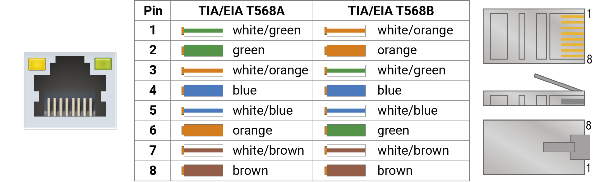
The Ethernet ports can be connected to a LAN hub, switch or router by a CATx cable. Even though both cable types (straight or cross) are supported and handled by the device, the pin assignment below is recommended.
Dante® RJ45 Connector
D series extenders provide standard RJ45 connectors for transmitting digital audio signal. Always use high quality Ethernet cable.
Wiring of CATx Cables
Lightware recommends the termination of LAN cables on the basis of TIA/EIA T 568 A or TIA/EIA T 568 B standards.
The TPN-CTU-X50 controller unit is supplied with a 3.81mm 3-pole 90° Reversed Gender Plug Phoenix® connector, which is used for connecting an occupancy sensor.
The first pin is a 24V logic input. The default state is high. Different type of sensors exist: some send high level, some send low level to this input when the room is occupied. Active-high or active-low logic can be configured for this port in LDC to support them.
The second pin has a constant 24V output voltage, and the third one is the ground.

OCS connector pin assignments
Voltage ranges for 1st pin are the following:
|
Input voltage [V] |
|
|
Logic low level |
0 - 0.8 |
|
Logic high level |
2V- 24V |
OCS Output Voltage Level: 24V (50mA).
Pull-up resistor is integrated on the input. Works automatically with open-drain type sensors. Requires an external 1kR pull-down resistor between input and ground pins when used with active-high type sensors.
In case of applying Leviton OCS (https://www.leviton.com/en/products/osc10-m0w), supplying a 1 kOhm external resistor between the 1st and the 3rd pins is necessary – see the example in the OCS - Occupancy Sensor section.
Compatible Plug Type
WR-TBL series (3.81mm 3-pole 90° Reversed Gender Plug Phoenix), type: WR-TBL Series 3483 - 3.81 mm.
WARNING!The occupancy sensor connector and the GPIO port are not compatible with each other due to the voltage level difference, please do not connect them directly.
3.2.11. GPIO - General Purpose Input/Output Ports
The TPN-CTU-X50 controller unit is supplied with an 8-pole Phoenix connector with six GPIO pins that operate at TTL digital signal levels, and can be set to high or low level (Push-Pull). The direction of the pins can be input or output (adjustable). Voltage ranges for GPIO inputs are the following:
|
Input voltage [V] |
Output voltage [V] |
Max. output current [mA] |
|
|
Logical low level |
0 - 0.8 |
0 - 0.5V |
30 |
|
Logical high level |
2 - 5 |
4.5 - 5V |
18 |
The maximum total current for the six GPIO pins is 180 mA.
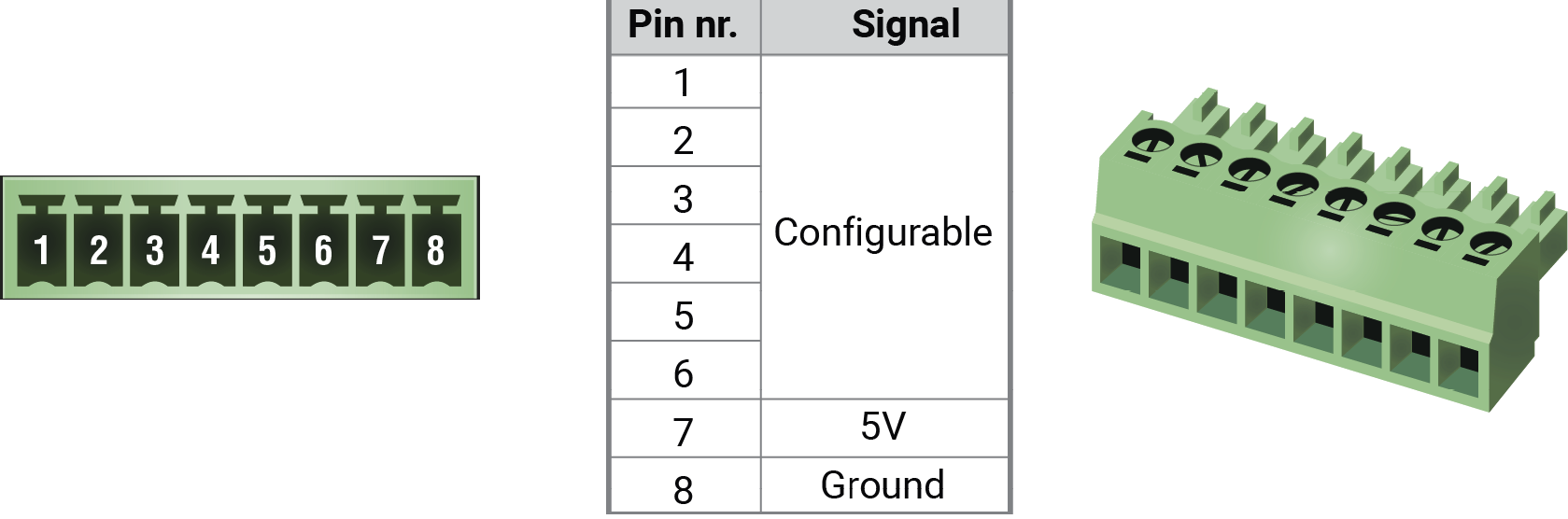
GPIO connector and plug pin assignments
INFO:The recommended cable for the connectors is the AWG24 (0.2 mm2 diameter) or the generally used ‘alarm cable’ with 4x0.22 mm2 wires.
Compatible plug type
Phoenix® Combicon series (3.5mm pitch 8-pole), type: MC 1.5/8-ST-3.5.
WARNING!The occupancy sensor connector and the GPIO port are not compatible with each other due to the voltage level difference, please do not connect them directly.
All TPN series models contain a 3-pole Phoenix connector, which is used for RS-232 serial connection.

RS-232 connector pin assignments
RS-232 Output Voltage Levels
▪Logic low level: 3V .. 15V
▪Logic high level: -15V .. -3V
Compatible Plug Type
Phoenix® Combicon series (3.5mm pitch, 3-pole), type: MC 1.5/3-ST-3.5.
You can find more information about RS-232 in the Serial Interface section.

IR emitter can be connected to the HDMI-TPN-TX107 and RX107 endpoint models with a TS (Tip and Sleeve) connector. It is also known as (3,5 mm or approx. 1/8”) audio jack, phone jack, phone plug, and mini-jack plug. The pin assignments are the following for the emitter:

|
|
|
Emitter – 2-pole TS |
|
|
1 Tip |
+5V |
|
2 Ring |
Signal (active low) |
|
3 Sleeve |
|
Pin assignment of the 2-pole TS connector

The small form-factor pluggable (SFP) is a compact, hot-pluggable optical module transceiver used for both telecommunication and data communication applications. It is a popular industry format jointly developed and supported by many network component vendors. The SFP interface supports data rates up to 1 Gbit/s. *
DEFINITION:The enhanced small form-factor pluggable (SFP+) is an enhanced version of the SFP that supports data rates up to 10 Gbit/s. *
OPTN series endpoint devices contain standard SFP+ slot for the fiber optical connections via SFP+ module or DAC cable. The installed SFP+ module can be singlemode or multimode as well.
|
OPTN endpoint devices |
|
|
Type of the slot |
SFP+ |
|
Maximum bandwidth per slot |
10 Gbps |
|
Transmitted signal |
Audio, video, Ethernet, RS-232, Infrared, USB KVM |
For the details about the DAC cable / SFP+ module installation, see the SFP+ Slot section.
Maximum Allowed Cable Length
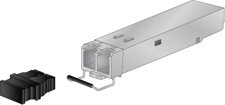
The maximum allowed optical or copper cable length depends of the installed SFP / SFP+ modules. Always check the specification of the optical modules before the fiber optical or copper cabling.
ATTENTION!Always apply equal length copper cables for both SFP+ to RJ45 modules in one endpoint device. Different cable lengths may cause data package loss during the transmission.
* Source: https://en.wikipedia.org/wiki/Small_form-factor_pluggable_transceiver
DIFFERENCE:Only HDMI-OPTN and HDMI-OPTN-SR series endpoint devices are built with SFP+ slot.
INFO:The SFP+ slots support the Plug and Play connection, which means OPTN devices do not need to be powered off before inserting or removing SFP+ modules or DAC cables.
3.3.1. Installation of the SFP+ Module
OPTN series endpoint devices use SFP+ module for the fiber optical connections. The optical module can be changed based on the recent application of the extender: it can be singlemode or multimode, or BiDi module, up to 10 GbE signal transmission.
Inserting and Cabling of SFP+ Modules
Step 1.Put up on the handle bar.
Step 2.Connect the module to the SFP+ port slot.
Step 3.Connect the LC connectors to the SFP+ module.
INFO:The SFP+ modules have a side that clips to the connector on the port of the switch, and is designed to prevent the module from being inserted the wrong way into the port. Do NOT force the module into the port.
Removing SFP+ Modules
Step 1.Disconnect the LC connectors from the SFP+ module.
Step 2.Pull down on the handle bar.
Step 3.Gently slide out the SFP+ module from the slot.
3.3.2. Installation of DAC Cable
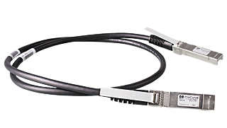
OPTN series endpoints can be connected via DAC (Direct Attach Copper) cables to the network switch. The cable type must support 10 GbE signal transmission.
Inserting the DAC Cable
Step 1.Push the plug of the DAC cable to the SFP+ port slot of the transmitter to stop.
Step 2.Push the other plug of the DAC cable to the SFP+ port slot of the receiver to stop.
Removing the DAC Cable
Pull the handle bar of the plug and gently slide out the cable from the slot.
INFO:See more details about the SFP+ interfaces in the SFP+ Slot section.
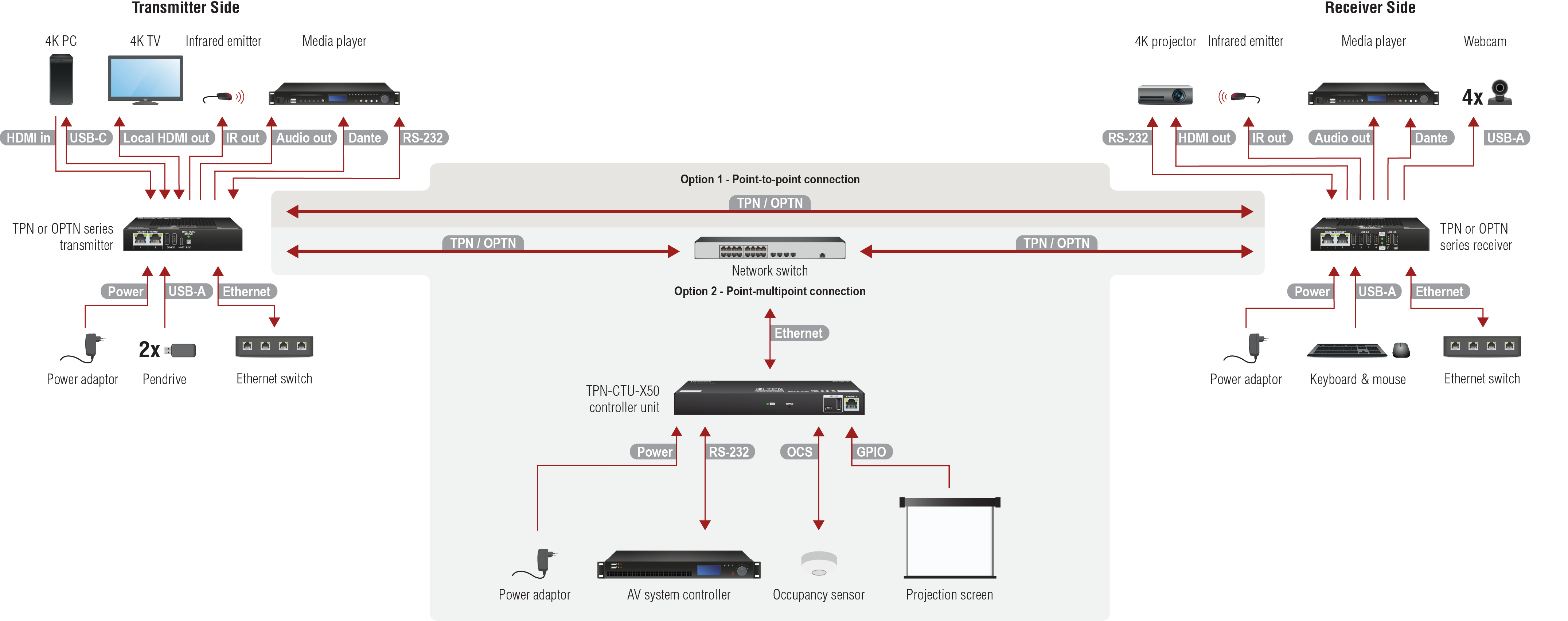
Schematic Drawing
The following schematic drawing shows the point-to-point connection type between a TPN/OPTN series transmitter and a receiver and the point-multipoint connection between the endpoint devices, the CTU and a network switch.
In case of extender mode (point-to-point connection) the presence of the CTU controller unit is not necessary, and the endpoint devices operate as TPX/OPTX extenders.
|
Transmitter Side |
|
|---|---|

|
Option 1 - Point-to-point connection - Connect a CATx cable between the TPN output port of the transmitter and the TPN input port of the receiver. In this case, the extender operates as a TPX device. Option 2 - Point-multipoint connection - Connect a CATx cable between the TPN output port of the transmitter and the RJ45 port of the 10G network switch. •WARNING! User Ethernet is also transmitted over the TPN interface, so be sure not to create a network loop. |

|
Option 1 - Point-to-point connection - Connect singlemode or multimode (depends on the installed SFP+ modules) fiber optical cables or DAC cables between the transmitter and the receiver. In this case, the extender operates as an OPTX device. Option 2 - Point-multipoint connection - Connect singlemode or multimode (depends on the installed SFP+ modules) fiber optical cables or DAC cables between the transmitter and the 10G network switch. •WARNING! User Ethernet is also transmitted over the OPTN interface, so be sure not to create a network loop. |

|
Connect the source (e.g. media player) to the HDMI input port of the transmitter by an HDMI cable. |
|
Connect the local sink devices (e.g. 4K TV) to the Local output port by an HDMI cable. The output port is a local loopback port in this case: the same stream received on the input port is transmitted forward. •INFO: The port is available in the TX207AU2K and TX200AU2K models. |
|
Optionally for analog output: connect an audio device (e.g. media server) to the analog audio output port by an audio cable. •INFO: The port is available in the TX207AU2K, TX100A and TX100AU2K models only. |

|
Optionally for Dante/AES67 output: connect a Dante/AES67 device (e.g. media server) to the Dante output port by a CATx cable. •INFO: The port is available in the TX107D and TX207DU2K models only. |
|
Connect the device to a LAN network. •WARNING! User Ethernet is also transmitted over the TPN/OPTN interfaces, so be sure not to create a network loop. |
|
Connect up to two USB 2.0 devices (e.g. pendrive/microphone/webcam/etc) to the Device ports. •INFO: The ports are available in the TX207AU2K and TX200AU2K models. |
|
Connect the host PC to the Host port by an USB-C cable. The port supports USB 2.0 standard and receives USB data only, no AV transmission allowed. •INFO: The port is available in the TX207AU2K and TX200AU2K models only. |

|
Optionally for Infrared extension: connect an IR emitter to the IR OUT port of the transmitter (command injection is available only with 3rd-party software). •INFO: The port is available in the TX107 model only. |

|
Optionally for RS-232: connect a device (e.g. media player) to the RS-232 port. |

|
Powering on the devices is recommended to do as the final step during the installation. Please check the Powering Options section for the options. |
|
Receiver Side |
|
|---|---|

|
Option 1 - Point-to-point connection - Connect a CATx cable between the TPN output port of the transmitter and the TPN input port of the receiver. In this case, the extender operates as a TPX device. Option 2 - Point-multipoint connection - Connect a CATx cable between the TPN input port of the receiver and the RJ45 port of the 10G network switch. •WARNING! User Ethernet is also transmitted over the TPN interface, so be sure not to create a network loop. |
|
|
Option 1 - Point-to-point connection - Connect singlemode or multimode (depends on the installed SFP+ modules) fiber optical cables or DAC cables between the transmitter and the receiver. In this case, the extender operates as an OPTX device. Option 2 - Point-multipoint connection - Connect singlemode or multimode (depends on the installed SFP+ modules) fiber optical cables or DAC cables between the receiver and the 10G network switch. •WARNING! User Ethernet is also transmitted over the OPTN interface, so be sure not to create a network loop. |

|
Connect the sink (e.g. 4K projector) to the HDMI output port of the receiver by a HDMI cable. |
|
Optionally for analog output: connect an audio device (e.g. active speakers) to the analog audio output port by an audio cable. •INFO: The ports are available in the RX107A-SR, RX107AU2K, RX107AU2K-SR, RX100A, RX100AU2K, RX100A-SR and RX100AU2K-SR models. |
|
|
Optionally for Dante/AES67 output: connect a Dante/AES67 device (e.g. media server) to the Dante output port by a CATx cable. •INFO: The port is available in the RX107D, RX107D-SR and RX107DU2K-SR models only. |

|
USB 2.0 ports: connect up to four USB 2.0 devices (e.g. pendrive/microphone/webcam/etc) to the receiver. USB HID ports: connect up to two USB HID devices to the receiver (preferably mouse and keyboard). •INFO: The ports are available in the RX107AU2K, RX107AU2K-SR, RX100AU2K and RX100AU2K-SR models. |
|
Connect the device to a LAN network. •WARNING! User Ethernet is also transmitted over the TPN interface, so be sure not to create a network loop. |
|
Optionally for Infrared extension: connect an IR emitter to the IR OUT port of the receiver (command injection is available only with 3rd-party software). •INFO: The port is available in the RX107 model. |
|
|
Optionally for RS-232: connect a device (e.g. 4K projector) to the RS-232 port. |

|
Powering on the devices is recommended to do as the final step during the installation. Please check the Powering Options section for the options. |
|
Controller Unit (CTU) Side |
|

|
Connect the device to the 10G network switch. |

|
Optionally for RS-232: connect a device (e.g. AV system controller) to the RS-232 port. |

|
Optionally connect an occupancy sensor to the OCS port. |

|
Optionally connect a device (e.g. a projection screen) to the GPIO port. |

|
Powering on the devices is recommended to do as the final step during the installation. Please check the Powering Options section for the options. |
HDMI-TPN series endpoint devices fulfill the PoE PD standard (IEEE802.3af), which means the TPN port can receive power over the Ethernet line.
ATTENTION!HDMI-TPN series extenders are not able to send remote power to each other.
Affected models:
▪HDMI-TPN-TX107
▪HDMI-TPN-TX107D
▪HDMI-TPN-TX207DU2K
▪HDMI-TPN-TX207AU2K
▪HDMI-TPN-RX107
▪HDMI-TPN-RX107D
▪HDMI-TPN-RX107A-SR
▪HDMI-TPN-RX107D-SR
▪HDMI-TPN-RX107AU2K
▪HDMI-TPN-RX107AU2K-SR
▪HDMI-TPN-RX107DU2K-SR
The TPN series devices can be powered in any of the following ways:
|
Option 1 - Local adaptors for both TX and RX |
Option 2 - Remote power via network switch 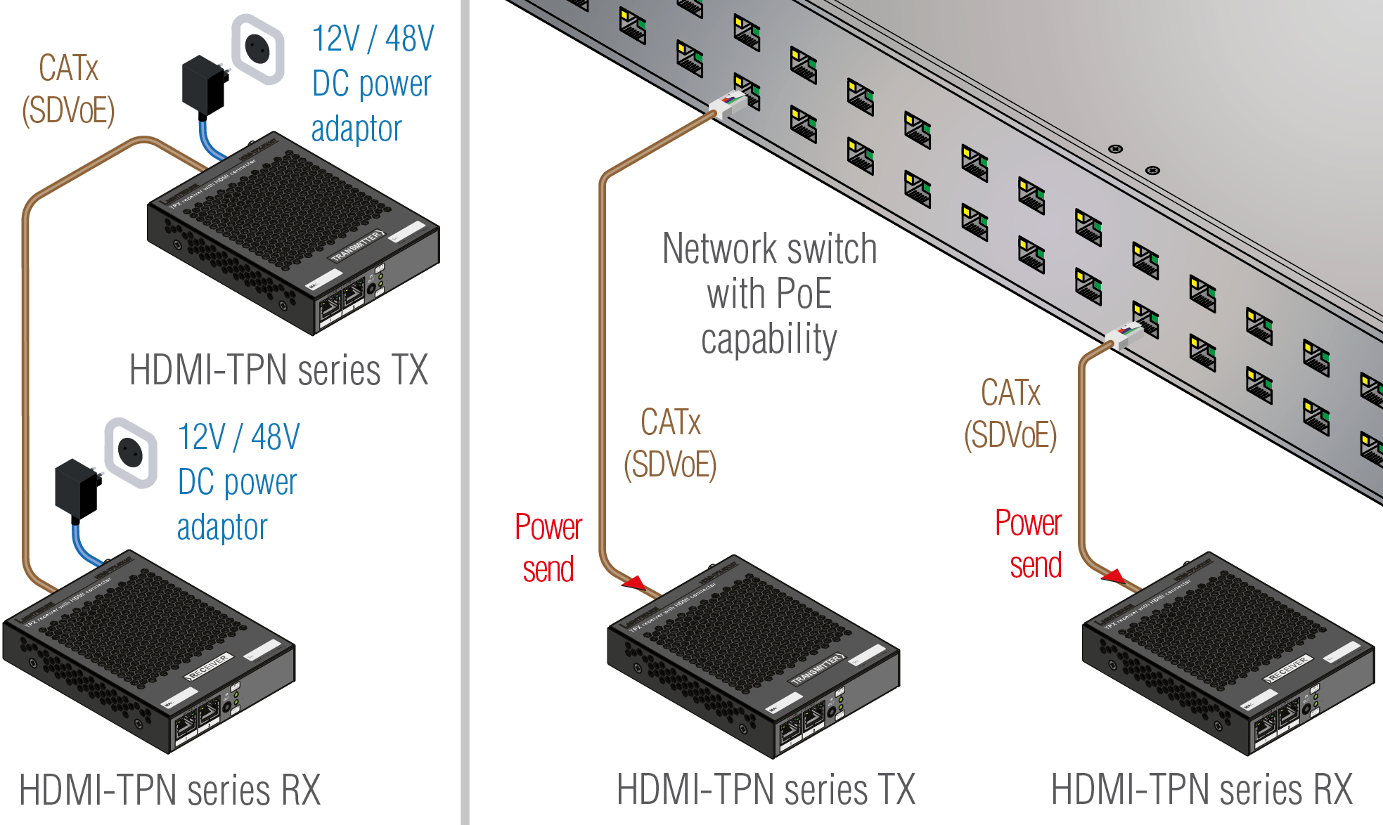
|
3.6. Ethernet Switch - Detailed Requirements
In the virtual matrix architecture a third party switch is used to transfer IP packets. In connection with this switch, the following criteria must be met:
▪10 Gbps non-blocking switch (capable of full bandwidth transmission between all ports)
▪Supports Internet Group Management Protocol version 2 (RFC 2236) snooping.
▪IPv4 (or Layer 2) Multicast Forwarding based on IGMP v2 snooping, with at least 16 addresses available for each endpoint, e.g. 4096 IPv4 multicast addresses for 256 endpoints.
Optional, but Highly Recommended Requirements:
▪Supports Link Layer Discovery Protocol (LLDP), in order to discover network topology.
▪Supports IEEE Std. 802.1Q VLAN tagging.
▪Supports IEEE Std. 802.1Q (formerly 802.1p) priority code point (PCP), and implements priority based queuing for at least 1 prioritized traffic class. This is required to guarantee uninterrupted media transmission regardless of the user traffic.
▪Supports IEEE Std. 802.1s (merged into IEEE Std. 802.1Q-2005) Multiple Spanning Tree Protocol (MSTP), in order to detect switching loops in VLAN’s.
ATTENTION!LLDP settings are basically not required to build up a TPN/OPTN matrix so it is called optional, however, Lightware highly recommends to set them up because LLDP is indispensable in system installation and diagnostics.
Installation and Network Guide for TPN-OPTN Extenders
For more details about requirements of the network switch please visit our website and download the application notes for TPN/OPTN systems:
https://go.lightware.com/guide-for-TPN-OPTN-extenders
4. CATx Cable Diagnostics for TPN Endpoints
The chapter summerizes the knowledges and best practices for the TPN CATx cable diagnostics for a better AV network. The following sections can be found in the chapter:
4.1. Bandwidth Requirement of SDVoE Technology
The TPN series transmitter and receiver devices are Lightware’s development allowing users to extend HDMI 2.0 signals up to 4K60 4:4:4 video resolution through 10G Ethernet networks.
The following table shows Lightware’s HDBaseTTM and AV over IP product lines grouped by required data rate.
|
Product Family |
Required Data Rate |
|
VINX |
1G |
|
Gemini (GVN) |
1G |
|
TPS (HDBaseTTM) |
10G |
|
TPX |
10G |
|
TPN |
10G |
|
UBEX |
10G / 20G |
4.2. Maximum Cable Extensions
The maximum applicable cable extension is defined by Semtech, the vendor of the SDVoE technology. Lightware has tested the maximum allowed cable lengths on the TPN endpoint devices.

|
Resolution |
CATx CAT6a AWG24 |
|
All resolutions |
100 m |
|
328 feet |
4.3. Recommended CATx Cable Types
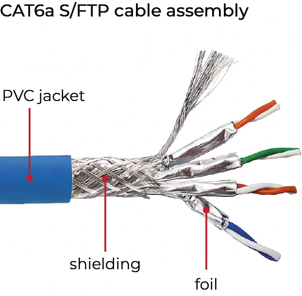
Lightware highly recommends using at least CAT6a AWG 24 shielded (S/FTP or S/UTP or SF/UTP or SF/FTP) or higher category 10G Ethernet cables for the TPX or TPN (SDVoE) connection between the transmitter/receiver and the network switch. Usage of e.g. AWG 28 Ethernet cables may reduce the extension distance significantly.
|
UTP Category |
Data Rate |
Shielded / Unshielded |
Protection Type |
Applicable for TPX / TPN Systems |
|
|
CAT5 |
Up to 100 Mbps |
Unshielded |
F/UTP U/FTP F/FTP |
|
|
|
CAT5e |
Up to 1 Gbps |
Unshielded |
|
||
|
CAT6 |
Up to 10 Gbps |
Unshielded |
|
||
|
CAT6 |
Up to 10 Gbps |
Shielded |
S/FTP S/UTP SF/UTP SF/FTP |
|
|
|
CAT6a |
Up to 10 Gbps |
Shielded |
|
||
|
CAT7 |
Up to 10 Gbps |
Shielded |
|
||
|
CAT7a |
Up to 10 Gbps |
Shielded |
|
||
Recommended CATx Cable Model
▪Draka MFO 23
=CAT7, S/FTP, AWG 23
=10GBase-T certified cable
=HDBase-TTM certified cable
=datasheet >>here<<
4.4. Testing the Reliability of the Cabling
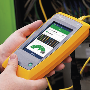
Lightware recommends testing the Ethernet cables before the final installation of TPX / TPN systems. One of the best cable testing tools is the Fluke Cable Tester, which is used by Lightware as well to ensure our quality standards.
▪Fluke Networks MicroScannerTM Cable / PoE Tester
=Recommended for TPX cabling tests
▪Fluke Networks LinkIQ™ Cable+Network Tester
=Recommended for TPN cabling tests
▪Fluke Networks Industrial Ethernet DSX CableAnalyzer™ Kit
=Recommended for TPX and TPN cabling tests
4.5. Keystones
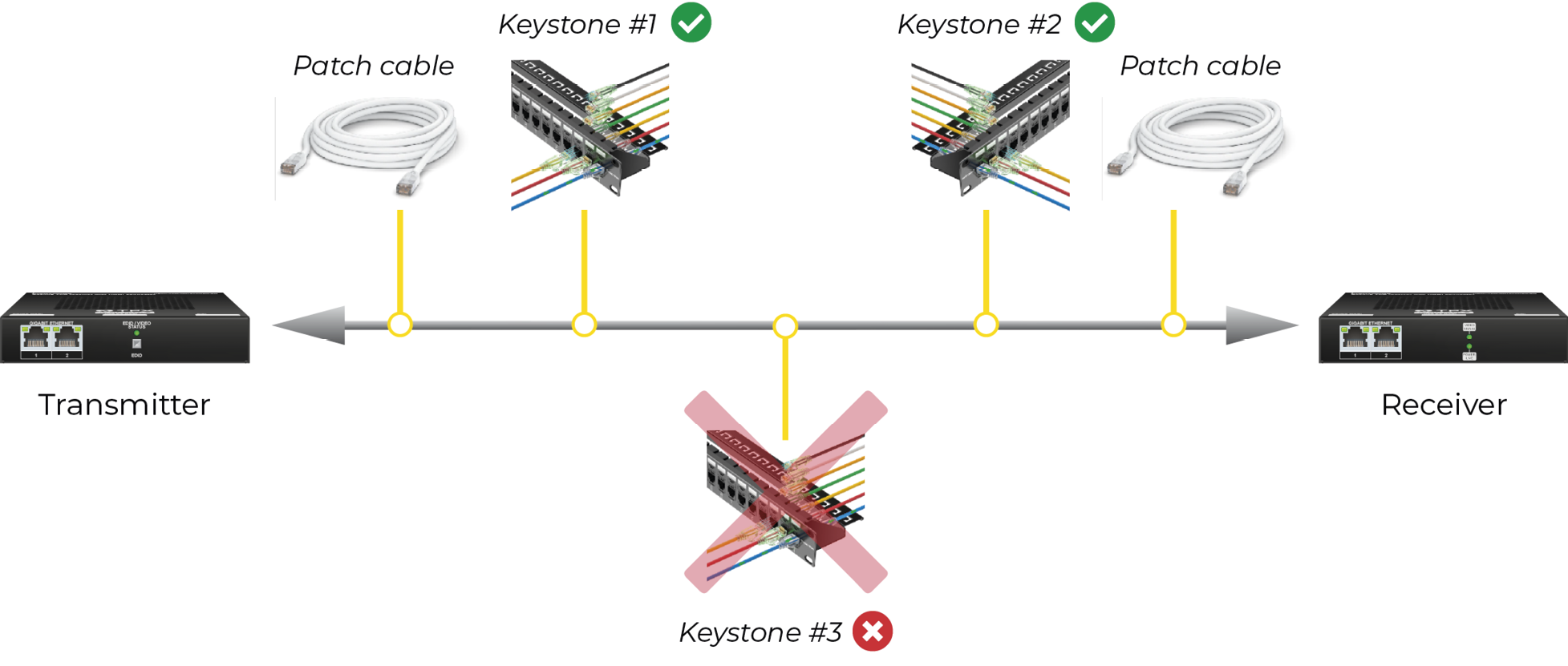
Lightware highly recommends applying a maximum of two keystones (and cable patches) - one on the transmitter and one on the receiver side. Applying more than two keystones may cause signal loss or jitter in the transmission, moreover the noise sensitivity of the system may be significantly higher.
All termination styles of keystones are acceptable (punch-down style, toolless, pass-through and coupler). The most important thing is to pay attention to the correct and trustworthy installation of the wires and make sure they do not move while in use.
When a keystone or patch cable is assembled, always make sure that the foil and the shielding are unharmed at the connector ends, otherwise the cable will be very sensitive to signal noises.
Example
4.6. Tips & Tricks for the Best TPX/TPN Experience
Follow these best practices for TPX and TPN systems easily installable and sustainable.
▪Check the cable length - shall be no longer than 100 m / 328 feet
▪Check the cable type - minimum requirement is CAT6a, shielded, S/FTP, AWG 24, but better cables result in a more relaible AV network
▪No more than two keystones - if it must be more than two, make sure the shielding and foiling is unharmed
▪Test the cables for 10G bandwidth before the installation
The following chapter describes the features of the TPN series devices in point-to-point and also in point-multipoint application modes; and also the special features of the CTU with a few real-life examples.
5.1. The Control Unit (CTU)
The Control Unit (CTU) is the brain of TPN system in the point-multipoint (networked) application mode. The CTU builds up the crosspoints; controls, manages and supervises the endpoints connected the TPN network.
When the endpoint devices are connected to the network and they are claimed by the CTU, the TPN matrix becomes one entity, which is managed by the CTU.
Port Diagram
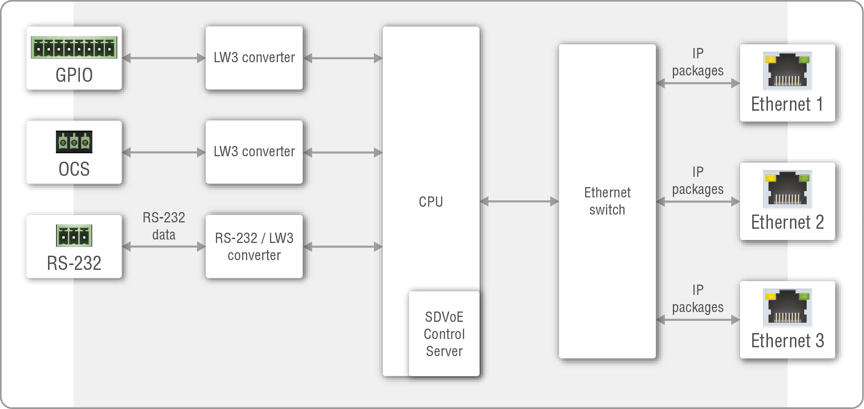
Port diagram of the TPN-CTU-X50 controller unit
The TPN-CTU-X50 control unit is equipped with three 10/100BaseT Ethernet ports with RJ45 connectors. The ports can be used for controlling and managing the device and accessing and configuring the TPN/OPTN AV network over the LARA modules. See more details about it in the AV System Configuration - Step by Step chapter.
The CTU has built-in SDVoE Control Server to discover and supervise the TPN/OPTN AV matrix. The feature can be activated in the Lightware Device Controller (LDC) software (see the Status section).
The device is also built with 2 pcs RS-232 ports with 3-pole Phoenix connectors for connecting to the control unit and sending serial messages to third-party devices. See more details in the Serial Interface section.
GPIO ports with an 8-pole Phoenix connector and an OCS port with a 3-pole Phoenix connector are built into the CTU for third-party device controlling purpose. See more details in the GPIO Interface and OCS Interface sections.
INFO:The CTU does not transmit AV signals.
The Functions of the CTU (in the point-multipoint application mode):
▪Endpoint and AV signal management by LARA:
=Dynamic crosspoint handling
=Monitoring of the network and the endpoints
=Automated features
=7/24 online network management
▪Backup and restore
▪Occupancy sensor (OCS) and GPIO control
▪Interface for third-party system controllers
The following sections are about controlling the endpoint devices and the Control Unit by a computer or any third-party controller.
INFO:It does not matter which device (the CTU directly or any endpoints) you want to use to establish connection with the TPN matrix, you will reach the CTU ultimately.
The following interfaces can be used to control the matrix:
|
Interface |
CTU |
Endpoints |
|
|
|
|
|

|
|
|
|


ATTENTION!The RS-232 port of the endpoint models can be used for controlling third-party devices only.
INFO:The USB control interface for the CTU will be added by a future firmware update.
Description
The endpoint devices and the Control Unit can be controlled over Ethernet interface. The ports are standard RJ45 connectors in the case of endpoint and the CTU as well.
The matrix can be configured with the following tools:
▪Lightware Device Controller (LDC) software (details: Ethernet Tab);
▪REST API protocol commands (details: Ethernet Port Configuration);
▪LW3 protocol commands (details: Ethernet Port Configuration).
TPN System Control over Ethernet - Example
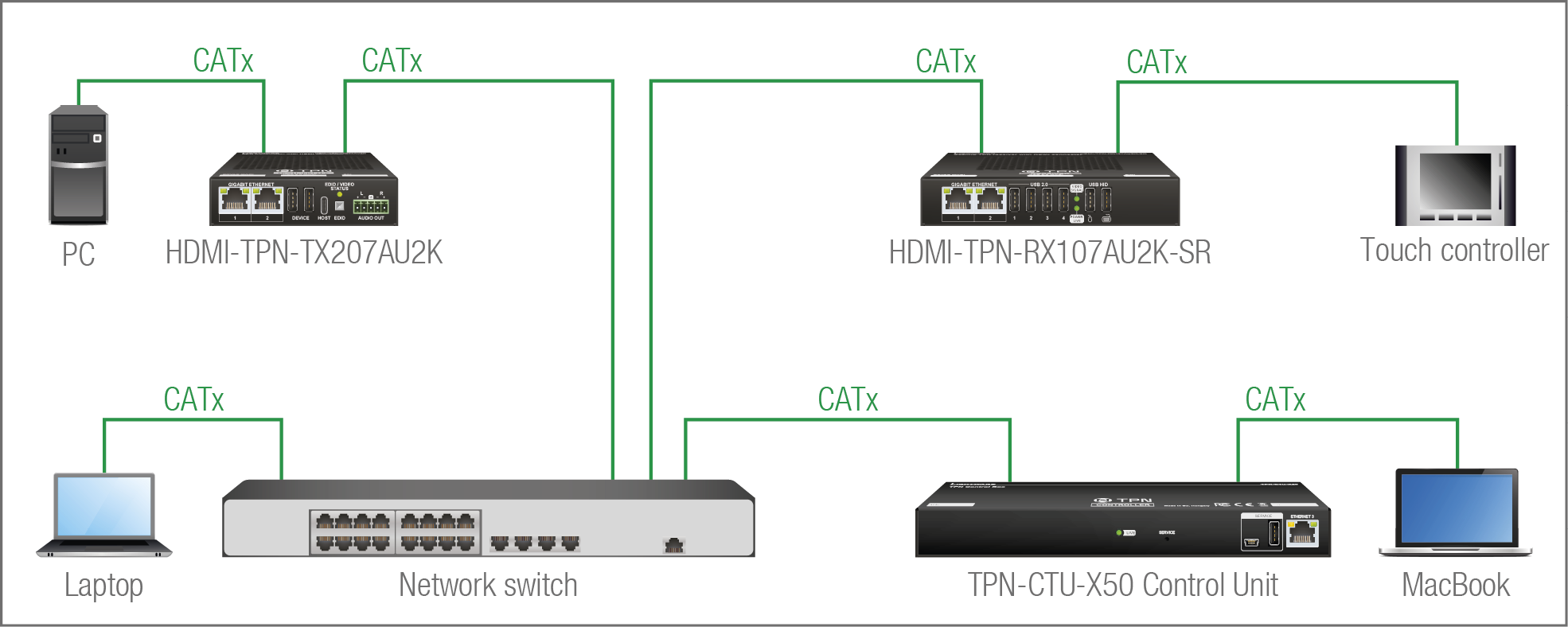
The Concept
The matrix has one transmitter and one receiver connected to a network switch and supervised by the MMU. There are four control devices connected to the network: a PC to the transmitter, a touch controller to the receiver, a laptop to the switch, and a MacBook to the CTU. It does not matter which device you want to use for controlling, all of them reach the CTU and you can configure the matrix.
This section is about the serial interface of the CTU.
ATTENTION!The RS-232 port of the endpoint devices cannot be used for controlling the TPN matrix.
Description
The Control Unit contains a 3-pole Phoenix connector for serial communication. The interface can be used for controlling the CTU itself or the TPN matrix.
The matrix can be configured with the following tools:
▪Lightware Device Controller (LDC) software (details: RS-232);
▪REST API protocol commands (details: Serial Port Configuration);
▪LW3 protocol commands (details: Serial Port Configuration).
TPN System Control over RS-232 - Example
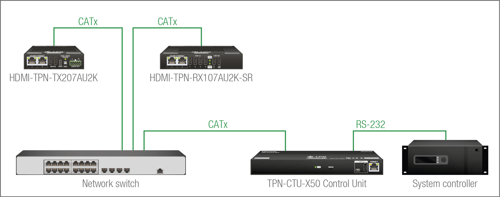
The Concept
The endpoint devices are connected to the TPN matrix over the network switch via the TPN ports. The CTU is controlled by the system controller over the serial interface by LW3 protocol commands. All AV related actions are available with LW3 protocol, e.g. crosspoint switching, EDID management, etc.
5.3. AV Interface
The section describes the audio and video routing and features of the various endpoint models of the TPN and OPTN ecosystem.
5.3.1. Port Diagrams
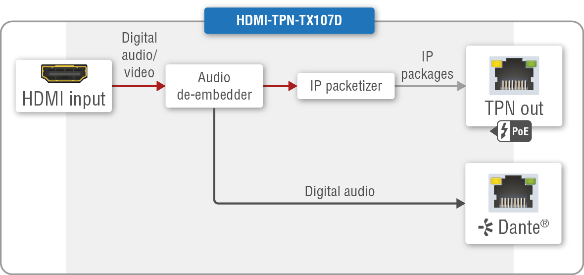
HDMI-TPN-TX107
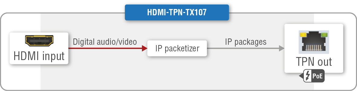
HDMI-TPN-TX107D
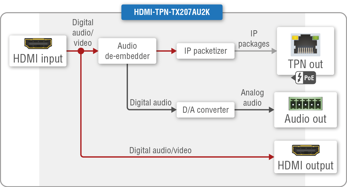
HDMI-TPN-TX207AU2K
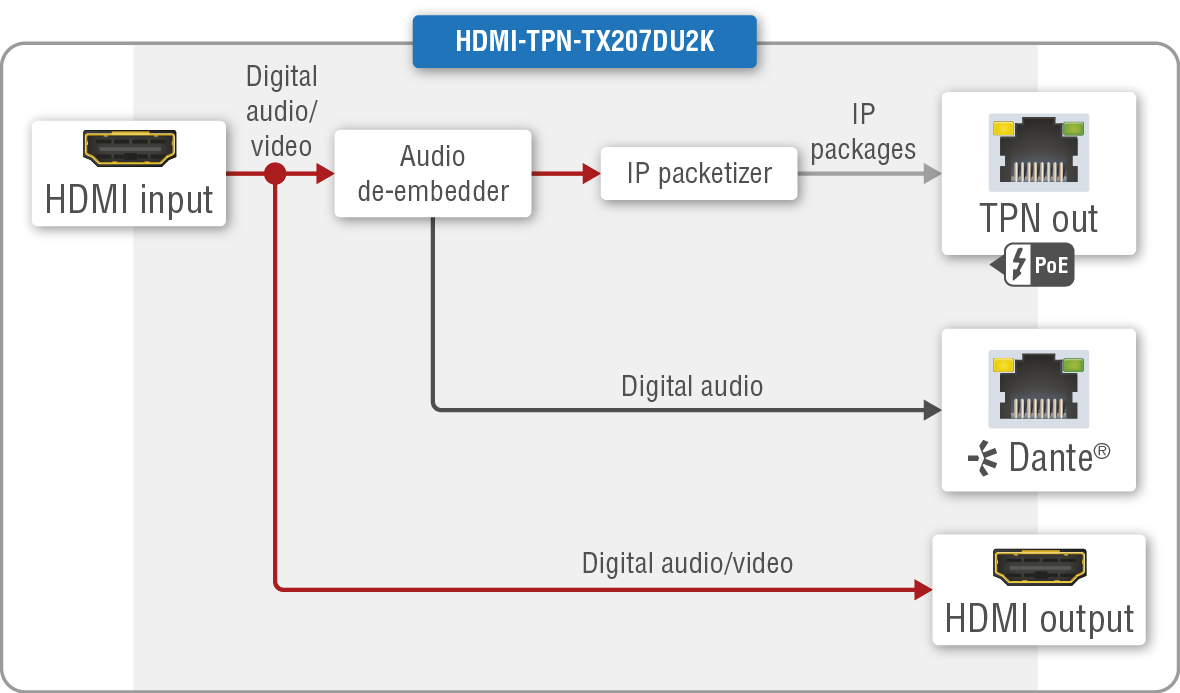
HDMI-TPN-TX207DU2K
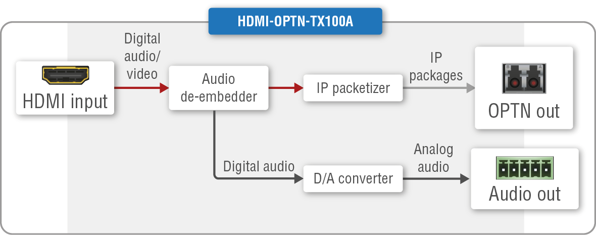
HDMI-OPTN-TX100A
HDMI-OPTN-TX200AU2K
HDMI-TPN-RX107

HDMI-TPN-RX107D
HDMI-TPN-RX107A-SR and HDMI-TPN-RX107AU2K-SR
HDMI-TPN-RX107AU2K
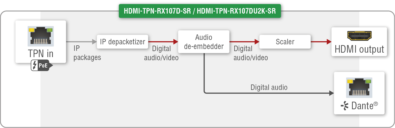
HDMI-TPN-RX107D-SR and HDMI-TPN-RX107DU2K-SR
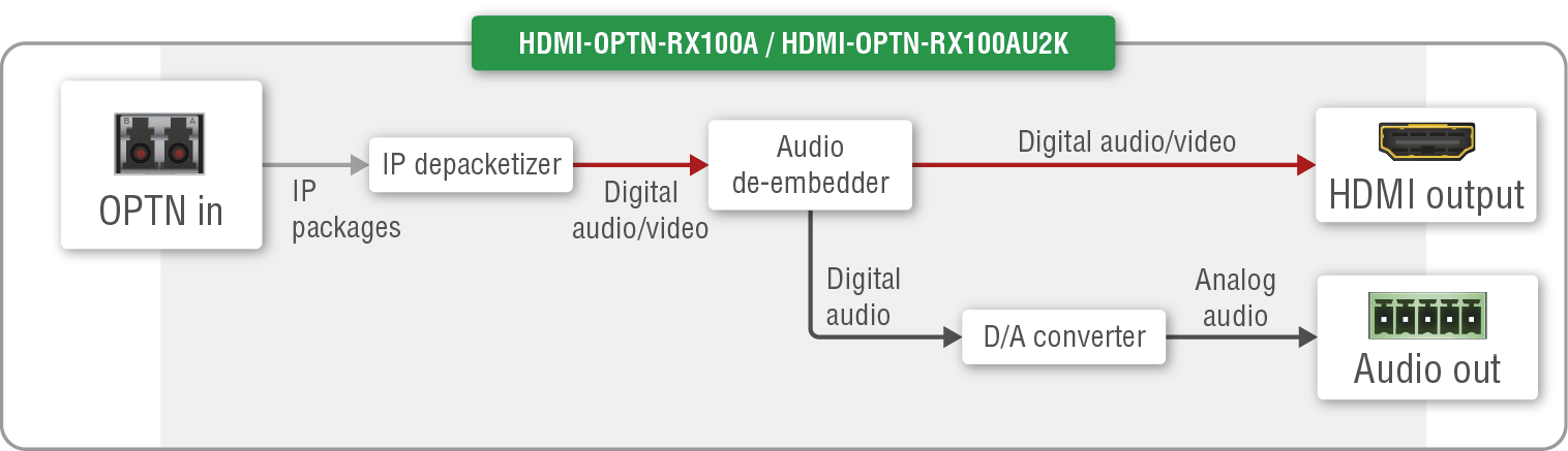
HDMI-OPTN-RX100A and HDMI-OPTN-RX100AU2K
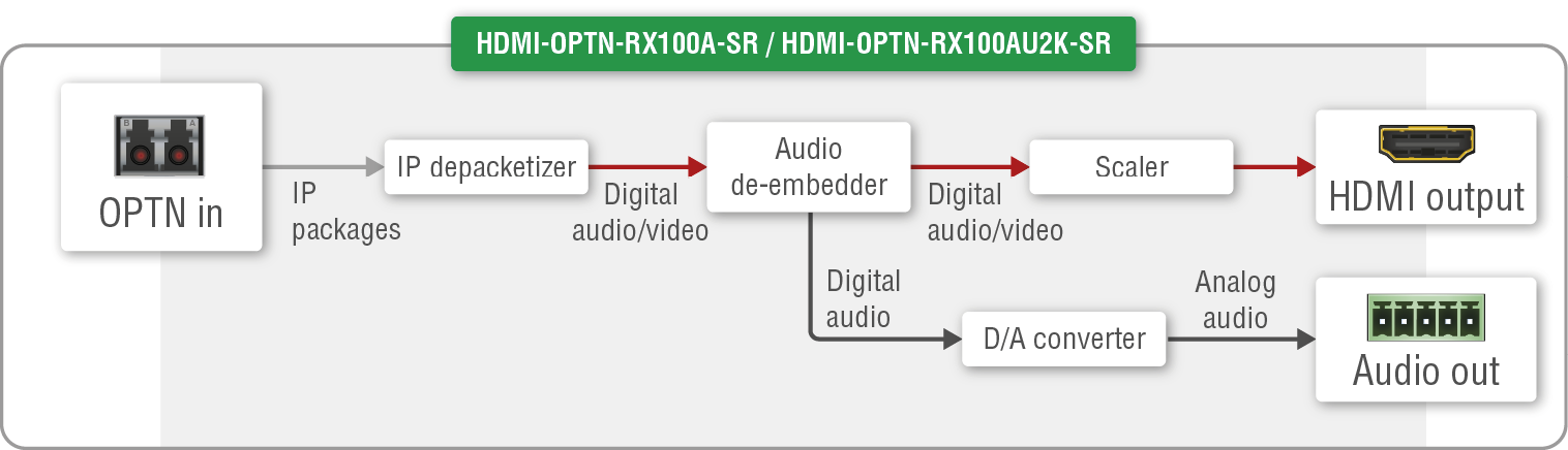
HDMI-OPTN-RX100A-SR and HDMI-OPTN-RX100AU2K-SR
Description
The endpoints and the Control Unit are connected to the network switch and these devices together create the TPN / OPTN matrix. The matrix is dynamic, which means the newly connected endpoint devices can be discovered by the CTU.
Transmitters
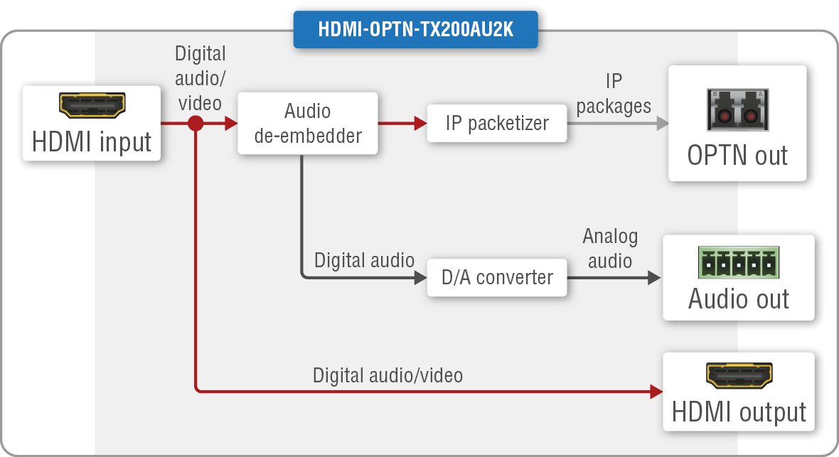
The TPN and OPTN series transmitters can receive one HDMI 2.0 audio/video stream up to 4K@60Hz 4:4:4 resolution from the source devices over the HDMI input port. The signal is transmitted over the TPN or OPTN output port toward the receivers.There is no signal processing (scaling, color conversion, etc) available on the transmitter side except the signal compressing, see more details in the Signal Compression by the SDVoE Technology section about it. The HDMI output port of the TX207AU2K, TX207DU2K and TX200AU2K models is an HDMI loop-back port and can be used as local HDMI output.
The TX207AU2K, TX100A and TX200AU2K models have built with an analog audio output port, which de-embeds the audio signal of the HDMI stream and transmits it after the digital-to-analog signal conversion. The port supports 2-channel analog balanced signal with 48 kHz sampling frequency.
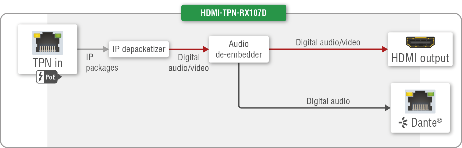
The TX107D and TX207DU2K models have built with an Dante®/AES67 digital audio output port, which de-embeds the audio signal of the HDMI stream and transmits it toward the audio sink device. The port supports 2-channel PCM signal with 44.1, 48, 88.2 and 96 kHz sampling frequencies.
The TPN output port fulfills the PoE PD (IEEE802.3af) standard, which means the device can receive power from the connected remote device (network switch).
ATTENTION!The TPN series endpoint devices are not able to send power to each other.
Receivers
The TPN and OPTN series receivers can receive one HDMI 2.0 audio/video stream up to 4K@60Hz 4:4:4 resolution from the transmitter over the TPN input port. The stream is transmitted toward to the sink device over the HDMI output port.
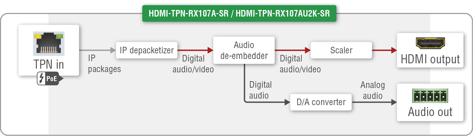
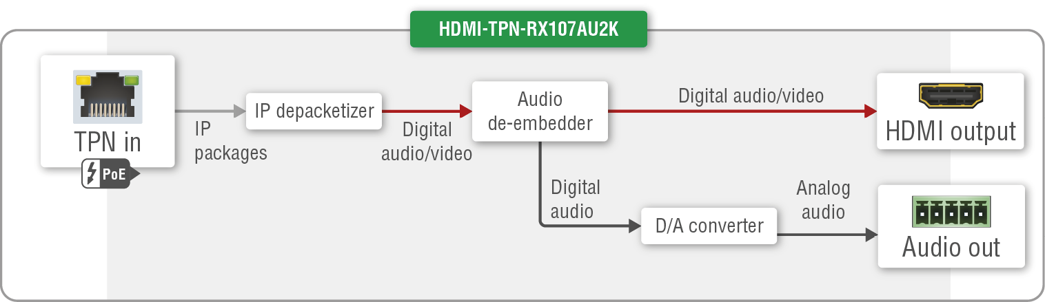
The RX107A-SR, RX207AU2K, RX207AU2K-SR, RX100A and RX100AU2K models are built with an analog audio output port, which de-embeds the audio signal of the HDMI stream and transmits it after the digital-to-analog signal conversion. The port supports 2-channel analog balanced signal with 48 kHz sampling frequency.
The RX107D, RX107D-SR and RX107DU2K-SR models have built with an Dante®/AES67 digital audio output port, which de-embeds the audio signal of the HDMI stream and transmits it toward the audio sink device. The port supports 2-channel PCM signal with 44.1, 48, 88.2 and 96 kHz sampling frequencies.
The -SR series receivers have an integrated scaler that can fit the resolution to the connected sink device. These receivers fulfills the seamless switching (clean cut) features during the changing of the crosspoint settings.
ATTENTION!A hot-plug event triggers EDID-based scaling in the SR series scaling receivers by default operation. See more details about it in the Scaler Operation by Default section.
The TPN input port fulfills the PoE PD (IEEE802.3af) standard, which means the device can receive power from the connected remote device (network switch).
ATTENTION!The TPN series endpoint devices are not able to send power to each other.
Control Unit (CTU)
The dynamic endpoint claiming, the signal routing (crosspoint settings) and managing the TPN network is the task of the Control Unit. All endpoint devices are available and configurable via the CTU.
See more details about the TPN/OPTN AV matrix controlling in the AV System Configuration - Step by Step chapter.
5.3.2. AV Features of the Endpoint Devices
The following comparison table summarizes the audio/video features of the TPN series endpoint devices.
|
SDVoE signal transmission interface |
Video interfaces |
Audio interfaces |
Features |
||||||
|---|---|---|---|---|---|---|---|---|---|
|
10GBaseT copper |
10G fiber optical |
HDMI input |
Local HDMI output |
HDMI output |
Analog audio output |
Dante/AES67 output |
Integrated scaler |
||
|
|
|
|
|
|

|

|
||
|
Transmitters |
HDMI-TPN-TX107 |
|
- |
|
- |
- |
- |
- |
- |
|
HDMI-TPN-TX107D |
|
- |
|
- |
- |
- |
|
- |
|
|
HDMI-TPN-TX207AU2K |
|
- |
|
|
- |
|
- |
- |
|
|
HDMI-TPN-TX207DU2K |
|
- |
|
|
- |
- |
|
- |
|
|
HDMI-OPTN-TX100A |
- |
|
|
- |
- |
|
- |
- |
|
|
HDMI-OPTN-TX200AU2K |
- |
|
|
|
- |
|
- |
- |
|
|
Receivers |
HDMI-TPN-RX107 |
|
- |
- |
- |
|
- |
- |
- |
|
HDMI-TPN-RX107D |
|
- |
- |
- |
|
- |
|
- |
|
|
HDMI-TPN-RX107A-SR |
|
- |
- |
- |
|
|
- |
|
|
|
HDMI-TPN-RX107D-SR |
|
- |
- |
- |
|
|
|
|
|
|
HDMI-TPN-RX107AU2K |
|
- |
- |
- |
|
|
- |
- |
|
|
HDMI-TPN-RX107AU2K-SR |
|
- |
- |
- |
|
|
- |
|
|
|
HDMI-TPN-RX107DU2K-SR |
|
- |
- |
- |
|
- |
|
|
|
|
HDMI-OPTN-RX100A |
- |
|
- |
- |
|
|
- |
- |
|
|
HDMI-OPTN-RX100A-SR |
- |
|
- |
- |
|
|
- |
|
|
|
HDMI-OPTN-RX100AU2K |
- |
|
- |
- |
|
|
- |
- |
|
|
HDMI-OPTN-RX100AU2K-SR |
- |
|
- |
- |
|
|
- |
|
|
5.3.3. Signal Compression by the SDVoE Technology
SDVoE technology applies signal compression only if the AV signal is above HDMI 1.4 standard, and the required bandwidth of the transmission would reach 10 Gbps.
The compression ratio on the TPN / OPTN output ports is 1.4 to 1.
ATTENTION!Lightware highly recommends using CAT6a AWG24 or higher category 10G Ethernet cables for the TPN (SDVoE) connection between the transmitter/receiver and the network switch. Usage of e.g. AWG28 Ethernet cables may reduce the extension distance significantly.
5.3.4. Dante® Audio Interface
DIFFERENCE:The following section refers to the TX107D, TX207DU2K, RX107D, RX107D-SR and RX107DU2K-SR models.
The D series models contain a special module that allows the de-embedding of the audio stream from the incoming HDMI signal and transmitting it as a 2-channel Dante® or AES67 source over the dedicated RJ45 connector. #dante #audio
Supported Audio
|
Audio type |
Signal support |
|
2-ch LPCM ** |
supported |
|
Multichannel |
not supported |
|
Compressed DTS/Dolby |
not supported |
** The supported sample rates are 44.1, 48, 88.2 and 96 kHz.
Dante® is a registered trademark of Audinate Pty Ltd.
Important Notes
▪The AES67 mode is supported which can be set in the Dante® Controller software.
▪Multichannel or encoded audio format cannot be de-embedded. In this case, no audio is sent to the Dante® network.
5.3.5. Audio Settings
The TPN/OPTN series transmitter devices transmit the embedded HDMI audio signal over the TPN (CATx) or OPTN (fiber optical) interfaces. The receivers accept and transmit it to the sink devices. The -A series transmitters and receivers can de-embed the HDMI audio and transmit it as an analog audio signal over the 5-pole Phoenix port.
The audio crosspoint can be set with the following ways:
▪using LARA modules: in this case the audio always follows the video signal, there is no independent audio layer. See more details about it in our dedicated document on the Lightware's website (PDF).
▪using BlueRiver AV Manager: the audio and the video signal can be switched independently. See more details about it in our dedicated document on the Lightware's website (PDF).
5.3.6. Example for Point-to-Point Connection
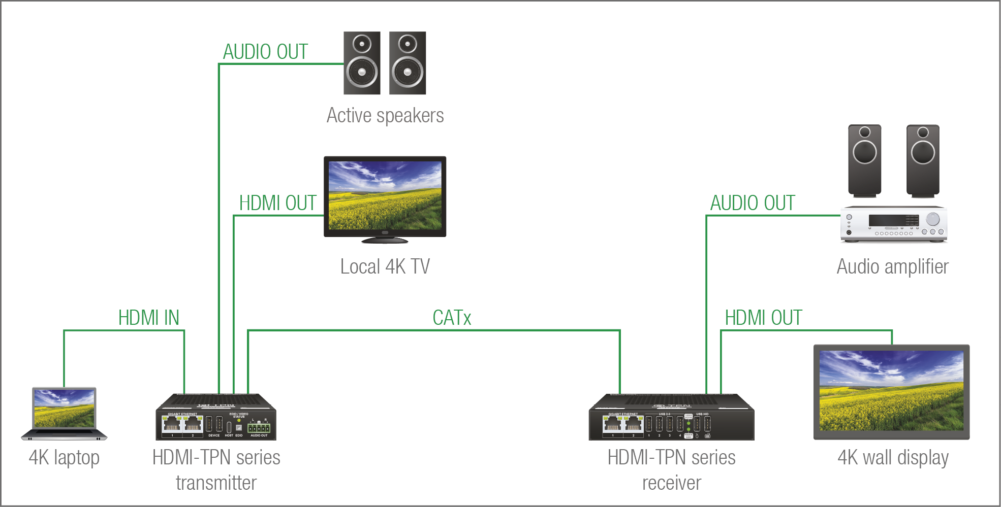
The Concept
A 4K laptop is connected to the HDMI-TPN series transmitter as the signal source. An audio sink device is also connected to the transmitter: active speakers on the analog audio output port. A local sink device is plugged into the HDMI output port of the transmitter where the transmitted signal can be supervised.
DIFFERENCE:Only the HDMI-TPN-TX207AU2K and HDMI-OPTN-TX200AU2K models are built with local HDMI out and the HDMI-TPN-TX207AU2K, HDMI-OPTN-TX100A and HDMI-OPTN-TX200AU2K models are built with analog audio output ports.
The IP packages are transmitted to the receiver over the 10G copper line.
The receiver has a video sink (4K wall display) and an audio sink device (audio amplifier) where the de-embedded audio signal of the HDMI stream is transmitted to.
DIFFERENCE:Only the HDMI-TPN-RX107A-SR, HDMI-TPN-RX107AU2K, HDMI-TPN-RX107AU2K-SR, HDMI-OPTN-RX100A and HDMI-OPTN-RX100AU2K models are built with analog audio output port.
5.3.7. Example for Point-Multipoint Connection
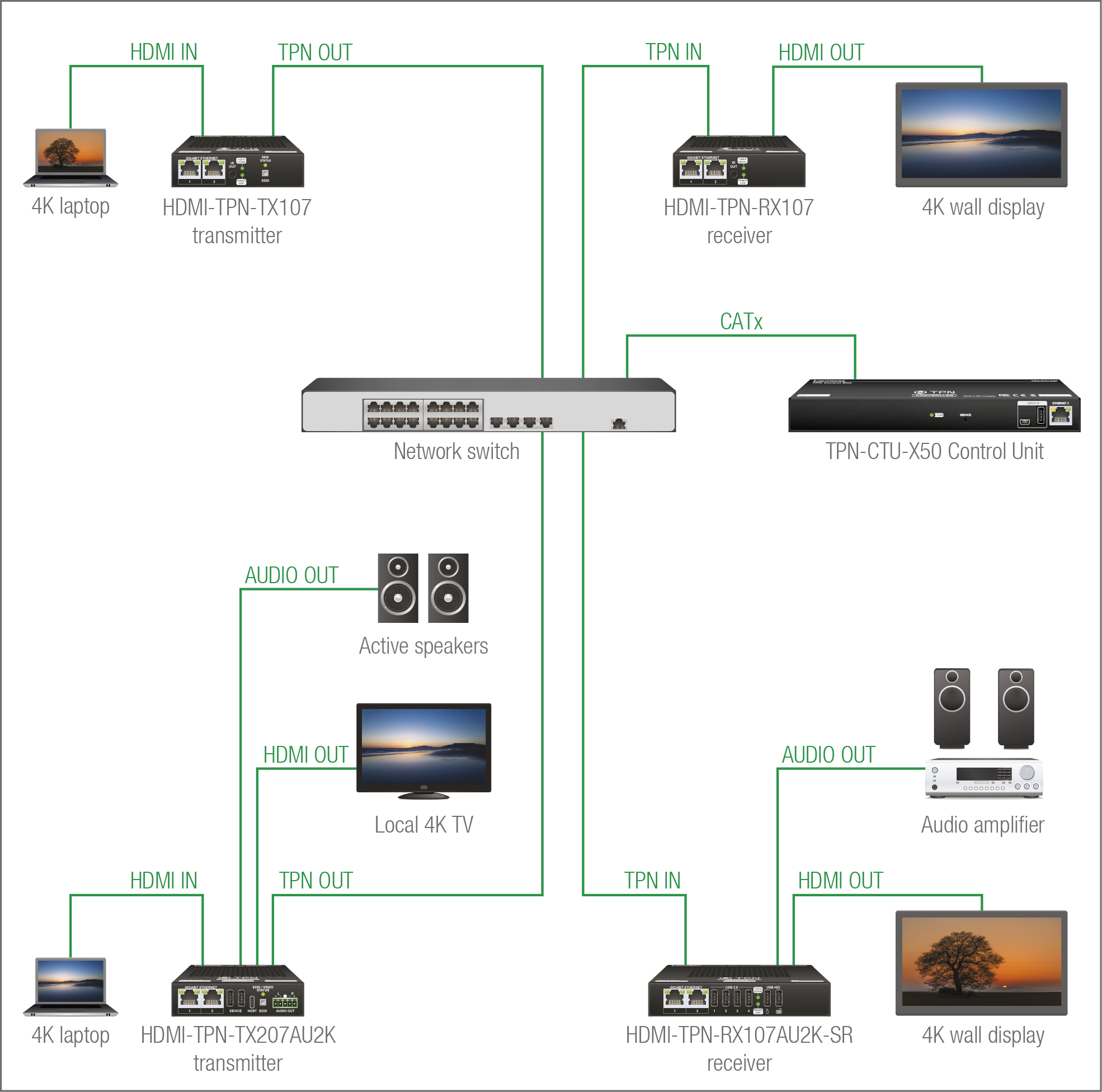
The Concept
This example shows a 2x2 TPN matrix with a network switch and the CTU in its center. The matrix contains two AV inputs (stream #1 and stream #2), two video outputs (one HDMI output per receiver), a local video output and two analog audio output (one for a transmitter and one for a receiver). The LARA drivers in the CTU build up the crosspoints and controls the AV system.
LARA Module
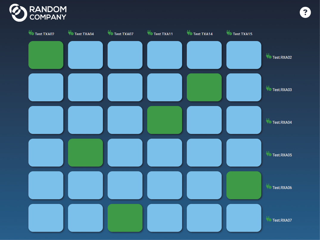
The TPN-CTU-X50 control unit is built with LARA automation software, which contains dedicated driver and UI modules for building up an SV matrix with SDVoE-based endpoint devices. The SDVoE driver manages the AV connections between the TPN and OPTN series endpoint devices. The user panel interface makes it possible to reach the crosspoint table anytime from a PC or a touchpanel as well.
There are two options to manage the TPN/OPTN AV network with GUI:
▪using LARA automation software - see the details in the AV System Configuration - Step by Step chapter;
▪using BlueRiver AV Manager - see the details in the Software Control - BlueRiver AV Manager chapter.
Learn more about the LARA automation software in the Lightware Advanced Room Automation (LARA) section.
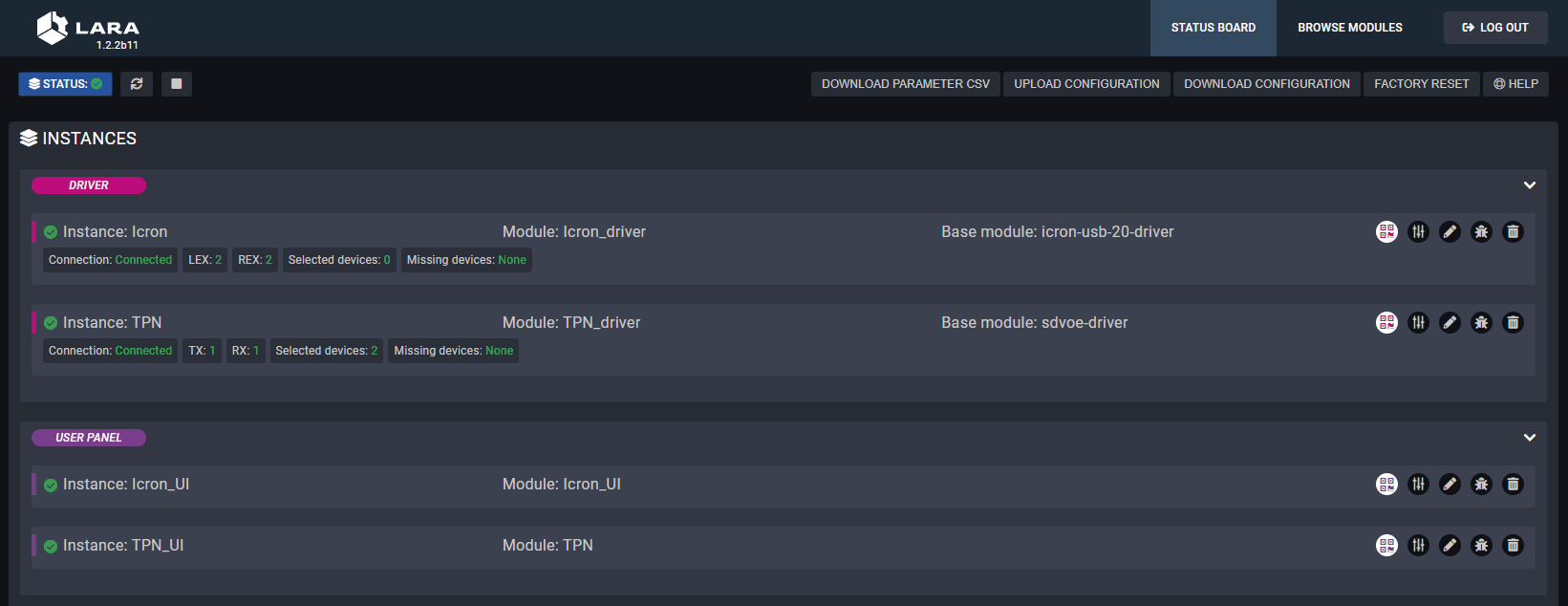
Status board of the LARA
5.4. Scaler Function of the Receiver
DIFFERENCE:Only HDMI-TPN-RX107A-SR, HDMI-TPN-RX107D-SR, HDMI-TPN-RX107DU2K-SR, HDMI-TPN-RX107AU2K-SR, HDMI-OPTN-RX100A-SR and HDMI-OPTN-RX100AU2K-SR receiver models have integrated scaler function.
The -SR receiver models are built with integrated scaler function. Five different scaler operation modes can be selected in the endpoint as following.
INFO:The scaling modes can be set in the LARA driver module.
There is no scaling on the output.
▪No frame drop
▪Ultra-low latency
▪No FPS conversion.
ATTENTION!This mode is validated for up to three network switch hops.
Scaler function is on.
▪The clock frequency of the receiver is syncronized with the transmitter's.
▪No frame drop.
▪Ultra-low latency.
▪No FPS conversion.
ATTENTION!This mode is validated for up to three network switch hops.
INFO:This mode is the default in the receiver.
Scaler function is on, optimized for fast switching between the source streams. This mode is the default in the receiver.
▪The clock frequency can be set by the user.
▪There is no network switch hop limitation.
▪Crosspoint switch can be performed fast.
▪One or two frames delay may happen.
Optimized for video wall application. Similar method as the fastswitch scaling.
▪There is no network switch hop limitation.
▪Crosspoint switch can be performed fast.
▪One or two frames delay and tearing effect on the video wall may happen.
Optimized for video wall application. Similar method as the genlock scaling.
▪The clock frequency of the receiver is syncronized with the transmitter's.
▪No frame drop.
▪Ultra-low latency.
▪No FPS conversion.
ATTENTION!This mode is validated for up to three network switch hops.
5.4.2. The Limitations of the Scaler
Bandwidth Related Limitations
The scaler function has bandwidth limitation, which in the practice means that the compression of the original picture is not possible below specific settings. When the scaling is not applicable, the error symptoms could be a flashing screen or displaying a black screen.
The following resolutions cannot be scaled while keeping the aspect ratio:
▪3840x2160 to
=640x480; 800x600; 960x1280; 1024x768; 1050x1400; 1200x1600
▪4096x2160 to
=1280x768; 1680x1050; 1200x1900
Color Space / Color Depth Related Limitations
If the scaler function is enabled in the receiver, the output is always RGB 8 bit/channel.
5.4.3. Scaler Operation by Default
ATTENTION!The following description is related to all models of -SR series scaling receivers.
If a hot-plug event (see examples below) happens with the scaling receiver, the device is restored to EDID-based scaling, therefore the preferred resolution of the sink device is being applied in the scaler. The desired scaler setting is required to set again.
Hot-plug Event Examples:
▪restarting of the scaling receiver
▪momentary power outage
▪unplugging and plugging again of the CATx cable in the TPN input port when the receiver is powered remotely (PoE)
▪unplugging and plugging again of the HDMI output cable
Does not Cause Hot-plug Event:
▪TPN connection error (e.g. unplugging and plugging again of the CATx cable in the TPN input port if the receiver is not powered over the CATx cable (PoE))
5.4.4. Example for Video Wall Application
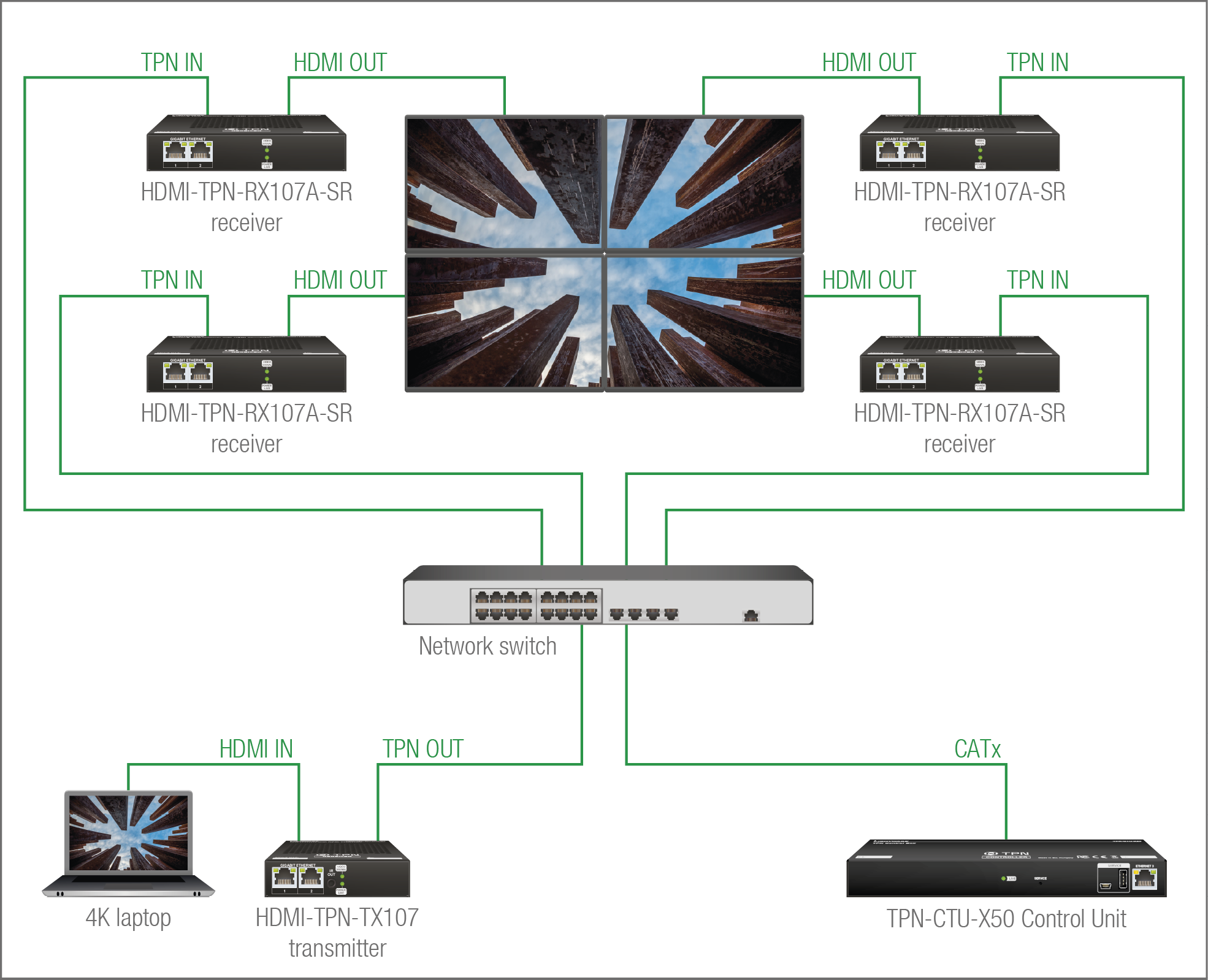
Installation example for the video wall
The Concept
The example figure shows a 2x2 video wall application with one transmitter and four scaling receivers, and a TPN-CTU-X50 device as a control unit. The recommended scaling modes:
▪Wall - recommended for a static video wall installation where no or few crosspoint switches are expected on the sink devices.
▪Wall FS - recommended for dynamic video wall installation where more crosspoint switches are expected.
5.5. Icron USB Interface
DIFFERENCE:Only HDMI-TPN-TX207AU2K, HDMI-TPN-RX107AU2K, HDMI-TPN-RX107AU2K-SR, HDMI-TPN-RX107DU2K-SR, HDMI-OPTN-TX200AU2K, HDMI-OPTN-RX100AU2K and HDMI-OPTN-RX100AU2K-SR models are built with USB KVM feature.
5.5.1. Port Diagram
TPN Series Extenders
Affected models:
▪HDMI-TPN-TX207AU2K
▪HDMI-TPN-TX207DU2K
▪HDMI-TPN-RX107AU2K
▪HDMI-TPN-RX107AU2K-SR
▪HDMI-TPN-RX107DU2K-SR
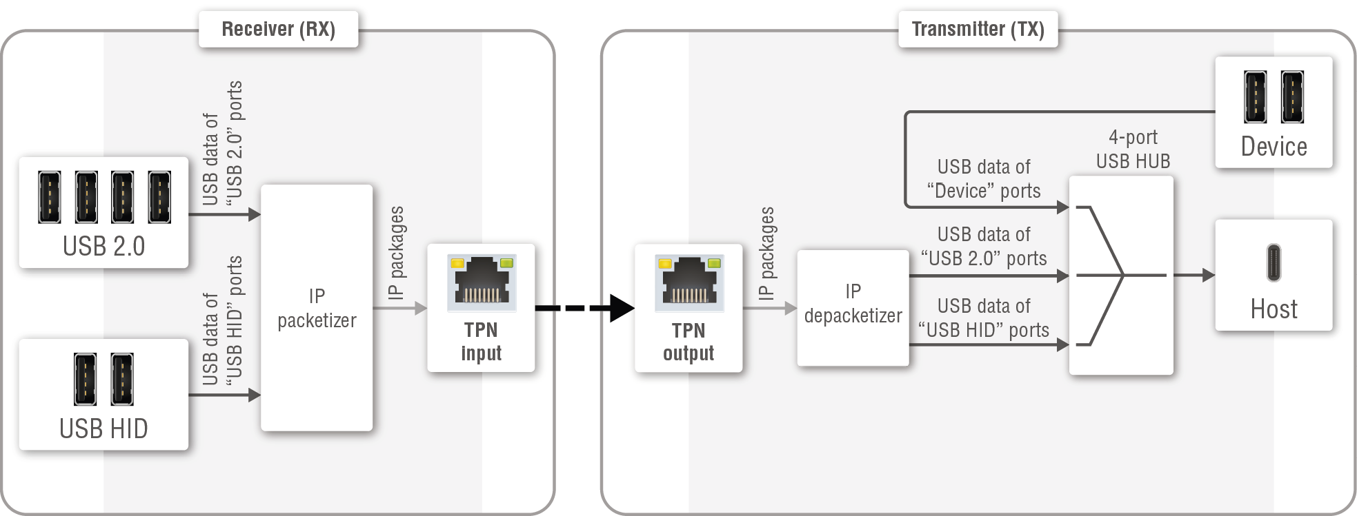
Port diagram of the USB KVM feature of the TPN TX-RX connection
OPTN Series Extenders
Affected models:
▪HDMI-OPTN-TX200AU2K
▪HDMI-OPTN-RX100AU2K
▪HDMI-OPTN-RX100AU2K-SR
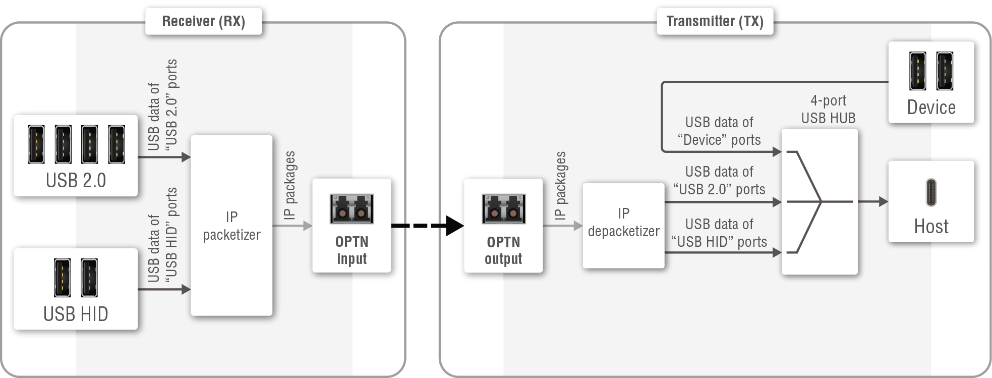
Port diagram of the USB KVM feature of the OPTN TX-RX connection
5.5.2. USB Configuration
Receiver (REX) Side
The AU2K series receivers are built with 2 pcs USB-A connectors labeled as USB HID for the peripheral devices (preferably keyboard and mouse) and 4 pcs USB-A connectors labeled as USB 2.0 for USB 2.0 devices (e.g. web camera, microphone, flash drive, mass storage, etc). The USB signal is transmitted to the transmitter over the TPN (CATx) or OPTN (fiber optical) interfaces.
The Icron module of the receiver is also called REX - Remote Extender.
Transmitter (LEX) Side
The AU2K series transmitters are built with 2 pcs USB-A connectors labeled as Device for the peripheral devices (preferably keyboard and mouse) and 1 pc USB-C connector labeled as Host for the host device (e.g. a computer). The host device can be controlled locally via the Device ports or remotely either via the USB HID ports of the receiver. The USB 2.0 ports of the receiver appear as an external USB device to the host computer.
INFO:The USB-C port receives USB data only, no AV signal transmission is accepted. It supports USB 2.0 standard only.
The Icron module of the transmitter is also called LEX - Local Extender.
Pairing the Extenders
Three different methods exist for pairing or connecting through a crosspoint a LEX to one or multiple REXs:
▪using LARA - see the details in the dedicated application note of the TPN/OPTN system configuration (PDF);
▪using BlueRiver AV Manager - learn more about it in the dedicated application note of the TPN/OPTN system configuration (PDF);
▪using Icron UDP command sending - see the details in the Pairing to a Device section.
5.5.3. USB KVM Transmission - Example
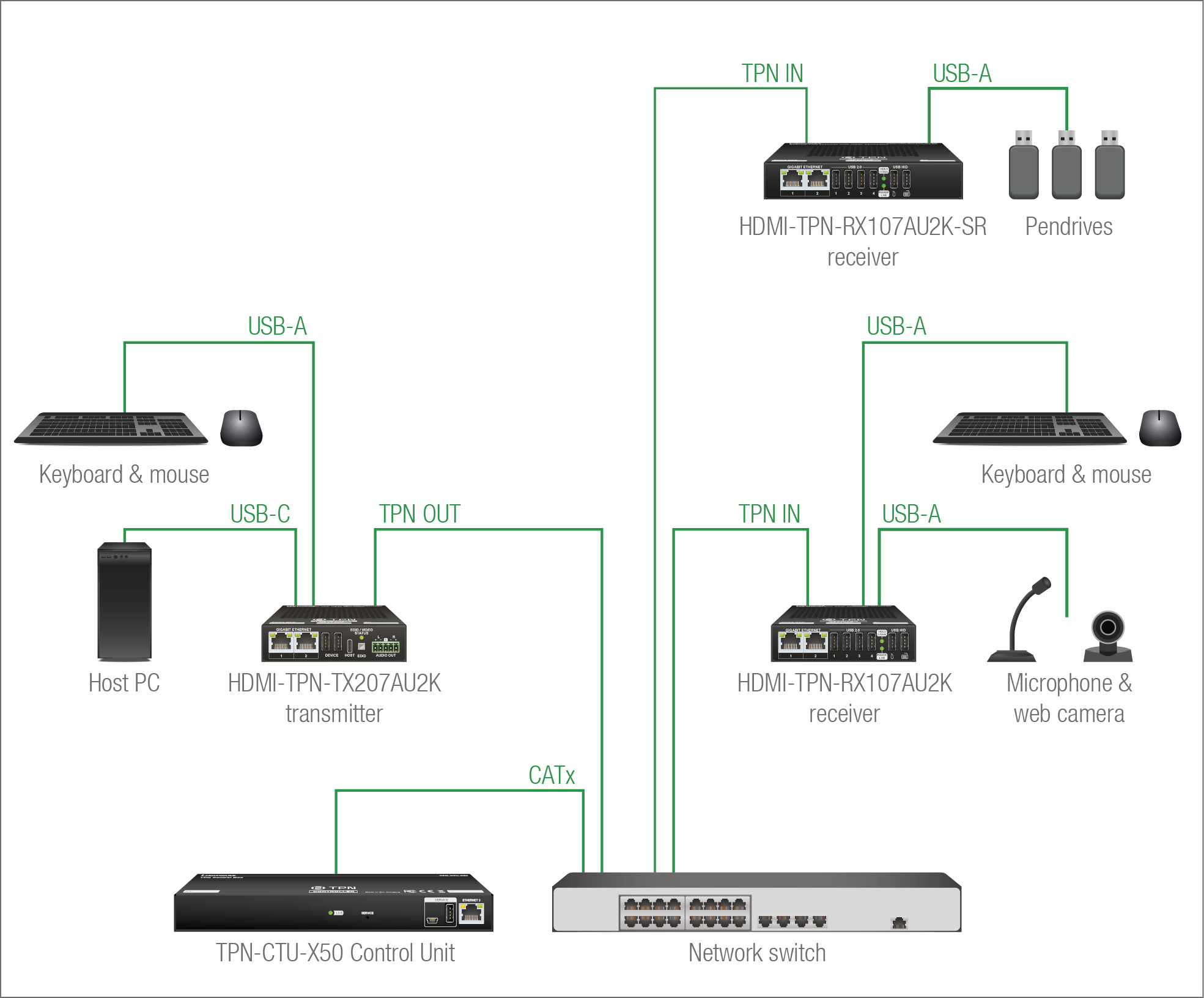
The Concept
The TPN system contains a transmitter (HDMI-TPN-TX207AU2K model as an Icron LEX) that connects to the host PC and a keyboard and a mouse for the local controlling; and the matrix also contains two receivers (as Icron REXs) that can be connected to the transmitter over the TPN interface via the 10G network switch.
The following USB devices are connected to the HDMI-TPN-RX107AU2K receiver:
▪a microphone and a webcamera on the USB 2.0 ports;
▪a keyboard and a mouse on the USB HID ports.
When the receiver (REX) is paired with the transmitter (LEX), the host computer can be controlled over the remote keyboard and mouse and the USB signal of the webcamera/microphone can be received by the host computer.
The following USB devices are connected to the HDMI-TPN-RX107AU2K-SR receiver:
▪three pendrives on the USB 2.0 ports.
When the receiver (REX) is paired with the transmitter (LEX), the host computer detects the remote pendrives as local USB devices.
5.6. Ethernet Interface
INFO:The CTU is built with three RJ45 Ethernet ports, the endpoint devices are built with two RJ45 Ethernet ports per unit.
The TPN/OPTN matrix can be controlled via Ethernet (standard RJ45 connector). The control interface can be reached via the CTU and the endpoint devices as well. This interface supports:
▪Configuration of the CTU by using the built-in website or the Lightware Device Controller software (LDC). For more information about the built-in web, see the Software Control - Built-in Web section; and about the LDC, see the Software Control - Lightware Device Controller section.
▪Control of the Lightware devices with LW3 command protocols. See more details about the Lightware protocol in the LW3 Programmer's Reference section.
▪Establishing the connection to the Lightware Device Updater V2 software and performing Firmware Update.
▪Creation of a local network, with Ethernet traffic passthrough.
▪The CTU provides WS/WSS services on its 80 (for WS) and 443 (for WSS) ports to control the device with LW3 protocol commands. For more details, see the WebSocket Service (WS, WSS) section.
▪REST API interface is also designed for controlling the device. See more details in the Lightware REST API Reference for CTU section.
5.7. Lightware Advanced Room Automation (LARA)

Lightware Advanced Room Automation (LARA) is a future-proof room automation platform that enables controlling both Lightware and 3rd-party devices in a meeting room area and also accessing remote services over the network. LARA has an easy-to-use graphical interface that allows the integrators to set up and deploy their system and also helps the technicians and IT personnel to check the system status and diagnose possible errors. LARA comes with built-in touchscreen control support, where a fully customizable graphical interface can be provided to literally any modern touchscreen device.
LARA eliminates the need for an external controller unit or PC, as it is embedded into the TPN-CTU-X50 control unit. Because of the modular design, the integrators can build their system based on existing modules (drivers, touch screens, services and more) or create their own. Thanks to the approach of open source modules, the integrators can easily modify or extend the existing modules, or use them as a base for their new solutions.
With LARA, integrators can set up the behavior of the meeting room by creating rules and setting various parameters, there is an option to write codes. JavaScript is the most widespread language today, which has a steep learning curve and huge online community. By using the popular NodeJS engine, the integrators can rely on the public NPM repository (http://www.npmjs.org) and use the free packages available there.
We are working hard to release new functionalities regularly and make LARA more and more user-friendly.
5.7.1. Opening the LARA interface
ATTENTION!When connecting to a device, you will need the 443 port for HTTPS connection, and optionally the 6107 port for raw TCP connection and the 80 port for HTTP connection.
Step 1.Enable LARA in your device. Navigate to the Settings/Network tab. First set a password for the 'admin' user, then enable LARA via the checkbox.
INFO:As LARA is capable of running NodeJS scripts accessing your network, it is imperative to prevent open access that could be used by a malicious attacker.
Step 2.Open LARA in either of the following ways:
=Via the Open LARA button under the System tab in the LDC, or
=By typing https://<ip_address>/lara into the address field of your browser. Even though any modern browser should work, we recommend using the latest Chrome or Safari versions. If you don’t know the IP address of your device, please use Lightware Device Controller to discover it on your local network.
LARA does not run by default, however, once it starts, it will remain running even after resetting the device or closing the browser, until it is stopped by the user. It can be disabled in the LDC software. Please be aware that calling factory reset will erase LARA configurations.
While a graphical interface is available for most of the general functions, LARA offers the option to use it with JavaScript codes for every step and modification for both basic and more advanced task creation. Wizard and JavaScript code usage can easily be combined for maximum efficiency.
Help
LARA offers an interface, which is available by clicking on the Help button near the top right corner. You can find the dedicated user manual (https://go.lightware.com/lara-pum) including descriptions, definitions, steps and examples that aid in understanding LARA and learning how to use it.
5.7.2. Running LARA
LARA uses modules and their instances as basic building blocks of a configuration.
Modules
Modules are software pieces that give a base to the processes in the LARA interface. There are five module categories available as follows:
▪Driver: a module connected to a certain device in the network
▪Logic: a module for organizing the other modules into a system
▪Userpanel: provides a user interface for the end user (e.g. tabletop control)
▪Service: a module connected to a certain service in the network (e.g. calendar services)
LARA modules have access to the devices' every port, connection interface and the entire parameter library of the LW3 tree.
There are several pre-made modules that can be found in LARA for quick and easy system setup. These modules can be found in the Browse Modules menu by clicking on the Create New button and choosing one of the options from the Base modules drop-down list.
▪SDVoE driver module - for discovring the endpoint devices and supervisoring the matrix.
▪Generic LW3 driver module - for controlling another Lightware device that supports LW3 protocol.
▪Generic TCP/IP driver module - for controlling any device that is available via TCP/IP connection.
▪OCS sensor serial message script module - for sending a serial message to a device (e.g. Display) if the Occupancy Sensor detects a signal.
▪Generic REST Client driver module: universal module for controlling third-party devices over HTTP(S) REST API (PUT, POST, GET, DELETE).
▪Signal present serial message script module - for sending a serial message to a device (e.g. Display) if a video signal is detected on a port.
Instances
Modules can be run as instances. Different parameters may be added to different instances for the same module to include every possible process in the desired system.
Instances can communicate with each other using Events and Methods.
ATTENTION!It is currently only possible to run all instances together, or run none of them.
Events
Every instance can emit Events when something happens. An event is always momentary, it will be emitted immediately when something triggers it. An event can be used by other logic or user panel instances, or even by the same instance itself.
Methods
Methods are software pieces in any instance, which can be invoked (called) to initiate an activity in the associated room equipment.
Rules
Rules allow setting up processes according to changes in the state of the device. A status change might dispatch an Event, which can trigger a rule. The rule will then be able to execute an Action according to the triggering Event. When defining a new rule, a triggering Event must be selected. In case of Logic and Userpanel modules any instance can be chosen as the source of the Event. In other cases only the given module's own Events may be selected.
Once an Event has been dispatched that triggered a rule, an Action will be launched. An Action may have an unlimited number of steps defined.
5.7.3. Downloading/Uploading a Configuration
The modules, or even the entire configuration can be downloaded to the computer as a .zip file, or a previously saved configuration can be uploaded to a device.
In case of downloading (and later uploading) a configuration of the module, these files are contained within the .zip file.
5.7.4. Status Board
The Status board offers real-time information about the connected devices through all running instances as Status Indicators. Such information might include connection status, signal presence, or even parameter status tracking. The indicators may show either static or self-refreshing information based on the current states of the device.
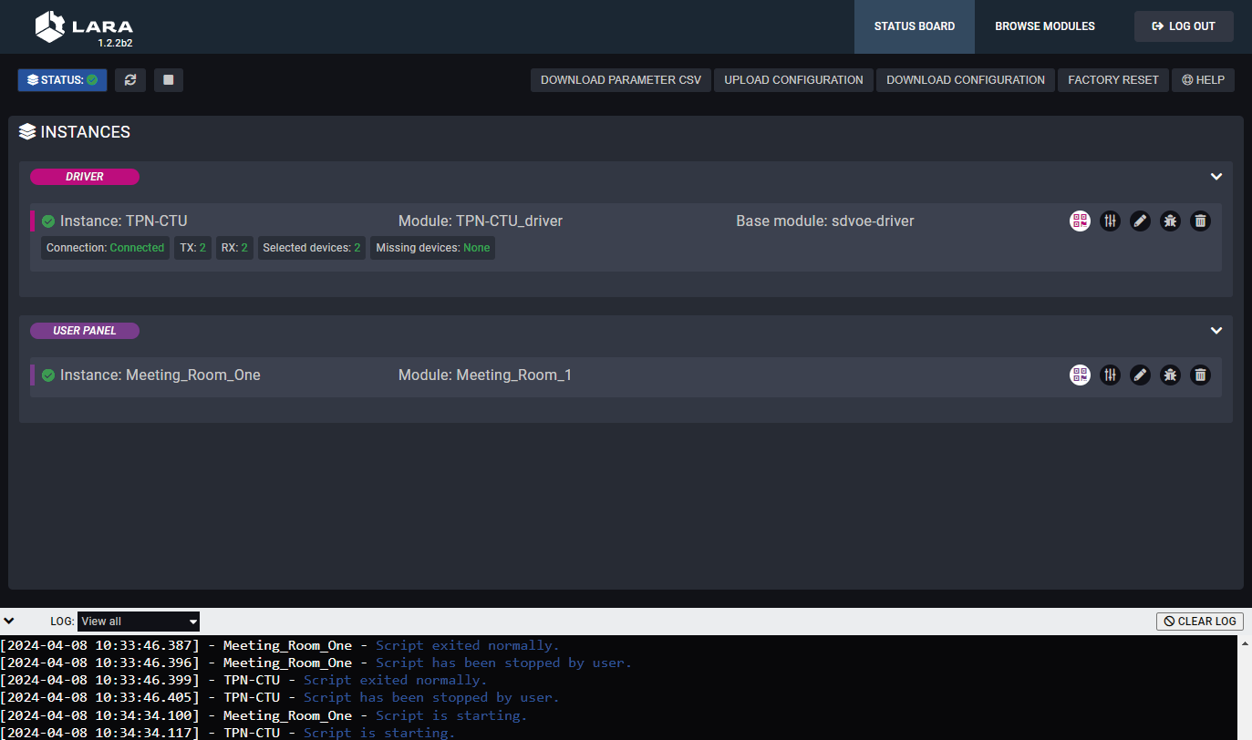
5.7.5. Touch Panel Support
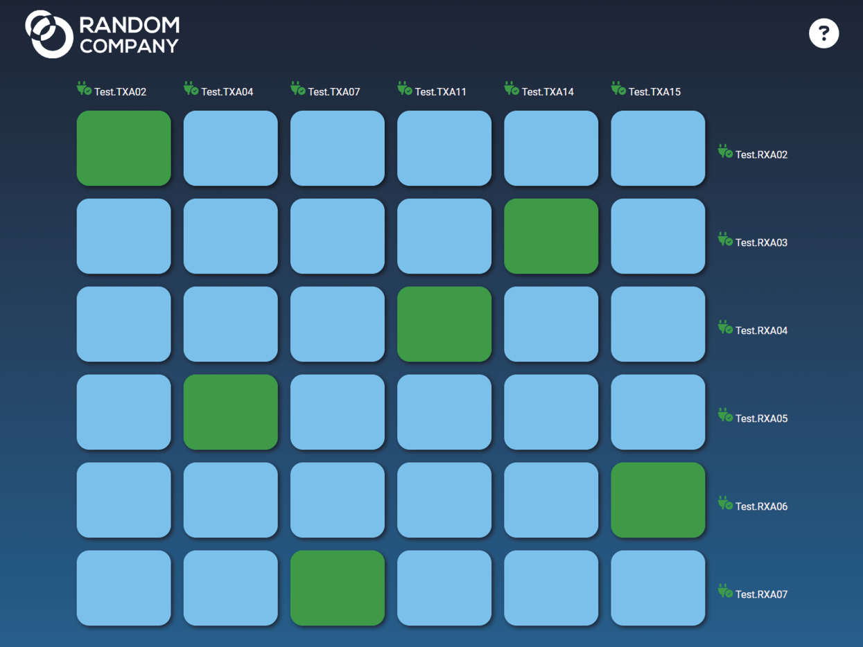
LARA offers support for any touch panel device that has a browser installed on it. With the use of Userpanel modules, you can easily upload project specific HTML/CSS/JS files to your devices, and edit or change them in LARA in real time. There is a Content option under a Userpanel module for the purpose of uploading and editing these files. It is also possible to create folders and subfolders for easy organization. Uploading can be done by dragging and dropping the files into the content section.
For proper operation, in the HTML code a unique ID shall be assigned to every HTML element where LARA interaction is required.
For more information, sample configurations and training materials, please visit https://www.lightware.com/en/products/Software/lara-software.
5.7.6. Limitations and Capabilities
Please consider the following when using LARA:
▪The CTU configuration contains the whole LARA configuration as well. If the device configuration is handled with the Backup/Restore feature, LARA settings can be preserved.
▪If LARA is running when the Lightware device (that runs LARA) is restarted, LARA will run automatically again.
▪A connected or an external device can be accessed via an Instance.
▪When LARA is running, all the defined Instances run together.
▪At most 20 Instances can be run parallel if the complexity of the Instances are at 'average' level.
▪The storage space is 128 MB for the Modules, Instances, user Module content and all codes.
▪The available RAM is 128 MB, LARA uses 56 MB in factory default state.
▪Restoring the factory default settings in the CTU device will delete the LARA configuration. This also happens during a firmware update if the firmware version jumps a major version (e.g. to v2.x, v3.x and so on).
The Specifications of a Complex Sample Configuration
▪It consists of 8 Instances:
=5 from the Generic-tcp-ip-client Module,
=1 from the SDVoE Module,
=1 from the User panel Module, and 1 from the Logic Module.
This configuration needs cca. 87 MB RAM space when running.
DIFFERENCE:The feature is available only in the TPN-CTU-X50 control unit.
These basic network security improvements help prevent unauthorized access to the TPN-CTU-X50 control unit:
▪Disable Ethernet Ports
▪Disable Network Services
The following table summarizes the ports, protocols, features and the security options.
|
Port number |
Protocol |
Function |
Affected software |
Port disable option |
Encryption |
Authentication |
Other features |
|---|---|---|---|---|---|---|---|
|
80 |
TCP |
HTTP port (LW3 over WS, REST API, LARA user panels) |
LDC, LDU2 |
|
|
|
Firmware update |
|
443 |
TCP |
HTTPS port (LW3 over WSS, REST API, LARA management GUI) |
LDC, LDU2 |
|
|
|
|
|
6107 |
TCP |
LW3 protocol |
LDC |
|
|
|
|
|
8001, 8002 |
TCP |
Serial over IP (RS-232) |
- |
|
|
|
|
|
224.0.0.251: 5353 |
UDP |
mDNS /Bonjour (Device Discovery) |
LDC, LDU2 |
|
|
|
|
|
230.76.87.82: 37421 |
UDP |
Remote IP |
LDC, LDU2 |
|
|
|


ATTENTION!The ports above are the most important ones, see the whole list of reserved ports of the TPN/OPTN system in the Reserved Ports and Security Options section.
ATTENTION!Be careful when combining the security functions; improper settings may cause malfunction.
INFO:The ports are necessary to be passed via a network switch/firewall for proper operation between the device and the softwares.
Internal Ethernet connections can be limited by enabling/disabling the Ethernet ports depending on the actual system configuration. Ethernet ports can be disabled in the following ways:
▪Lightware Device Controller (LDC) / Built-in web - see the details in the Ethernet Tab section.
▪LW3 protocol command - see the details in the Enabling/Disabling Ethernet Port section.
▪REST API protocol command - see the details in the Enabling/Disabling Ethernet Port section.
The CTU provides HTTP/HTTPS server services on its 80 (for HTTP) and 443 (for HTTPS) ports. The following services can be used via HTTP/HTTPS:
▪LW3 over WebSocket (WS, WSS) for LW3 protocol or using LDC for device control
▪REST API for device control
▪Serial message sending with REST API
▪Firmware update
▪WelcomeScreen image upload
▪LARA interface
▪Logfiles download from the device
ATTENTION!LARA management GUI is only available through HTTPS and it is password-protected.
To limit user access for HTTP/HTTPS server services, basic authentication can be turned on for the 80 and 443 ports separately.
ATTENTION!Authentication feature in TPN-CTU-X50 is not equal to the Cleartext login feature in the Advanced Control Pack v3 of the TPS family extenders.
The picture below illustrates the successful authentication process:
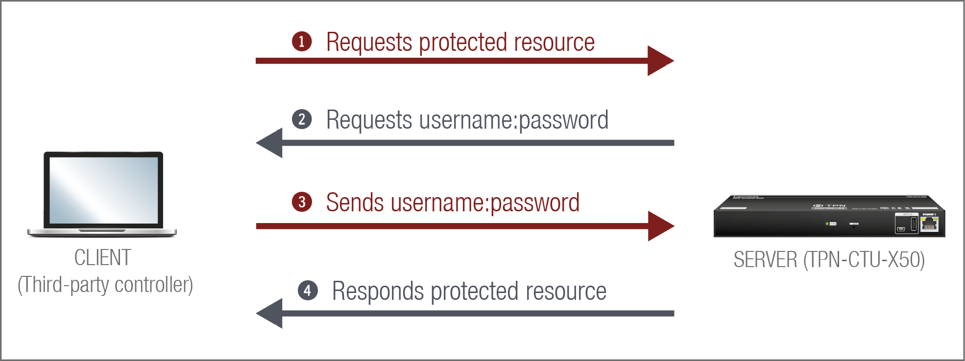
User
▪The switcher can manage one user (with fixed username: admin) with full access.
Password
▪No password is set by default, the authentication can be enabled after setting a password. The old password is necessary for modifying.
▪The following characters are allowed: Letters (A-Z) and (a-z) and numbers (0-9). Max length: 100 characters.
▪The device does not store the password string, so it can not be queried.
▪The password can be reset by calling factory defaults (Factory Reset (Service) Button for CTU).
Follow the instructions to set the authentication:
Step 1.Set the password with Lightware Device Controller (LDC) software (Network) or LW3 protocol command (Setting a Password for Authentication).
Step 2.Enable the authentication on the chosen port (HTTP: 80 or HTTPS: 443) with Lightware Device Controller software (Network) or LW3 protocol command (Enabling Authentication).
Step 3.Restart network services.
ATTENTION!The password will not be encrypted by this authentication mode, it remains accessible when the communication happens on HTTP.
5.8.3. Encryption (HTTPS, WSS)
HTTP protocol uses cleartext format for data transport. This method allows a third-party to listen in and eavesdrop on the transferred information.
HTTP request-response
To ensure the secure data transmission, the HTTP port (80) can be disabled, and all of the information can be transferred via HTTPS (443 port). HTTPS protocol encrypts the cleartext, so it becomes incomprehensible for a third-party and the data is kept secure.
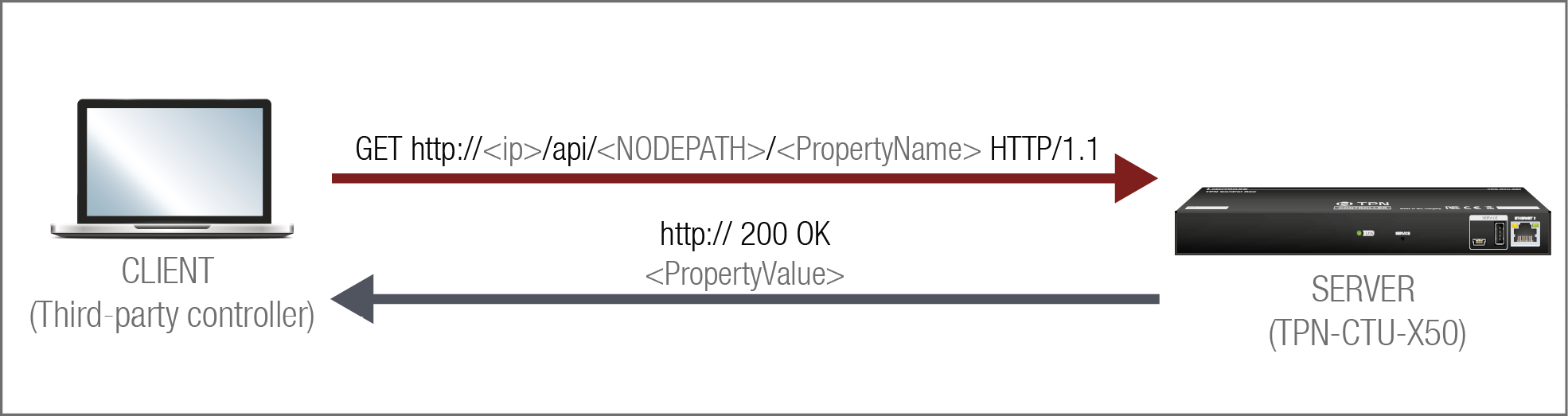
HTTPS request-response
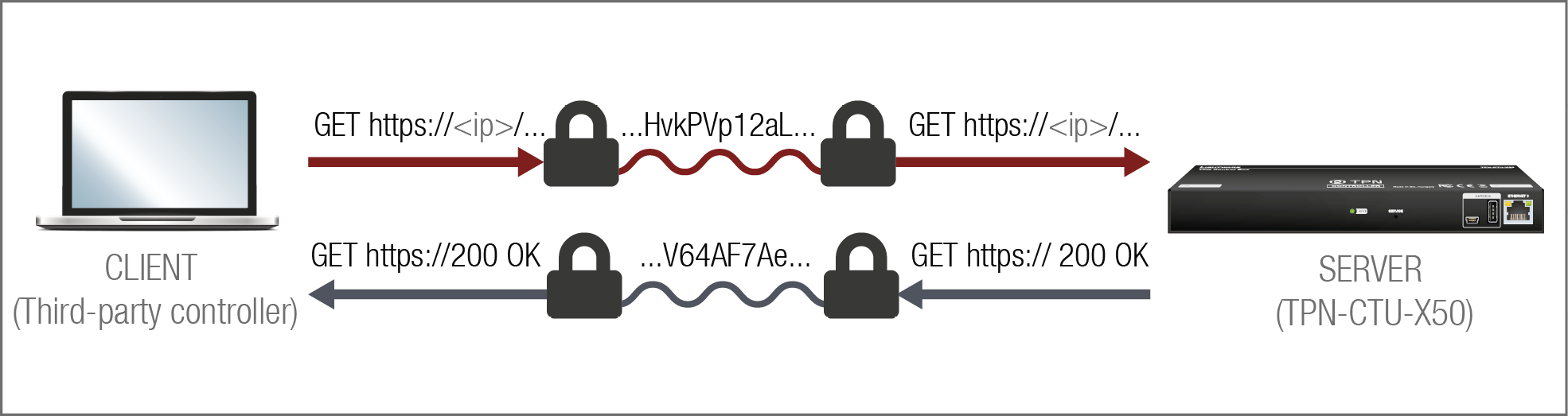
The same services are available on HTTPS as HTTP (for the detailed service list, see the HTTP/HTTPS section).
▪The CTU device generates a self-signed certificate, so the user does not have to deal with the configuration.
▪New certificate is generated after hostname changing or restoring the factory default settings.
▪Please ensure proper time and date setting in the CTU, because it affects the self-signed certificate (SSL) generation when using WSS or HTTPS. Improper time and date setting may lead to certificate rejection.
ATTENTION!HTTPS does not guarantee that the communication is secure. Make sure that the client communicates with the server directly, without any third-party element in the communication route (Man-in-the-middle attack).
Basic Security System Example
To keep the system protected, the unsecured ports should be disabled and data traffic should be managed by secured channels.
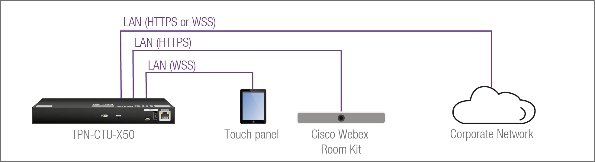
Step 1.Disable the HTTP port (80) and use HTTPS (443) instead.
The setting is available in the following ways:
▪Lightware REST API HTTP posts (see the details in the Enabling/Disabling Network Service Port section).
▪LW3 protocol commands (see the details in the Enabling/Disabling Service Port section).
Step 2.Set the password and enable the authentication.
The username is always fix (admin) and the password has to be set before the authentication is enabled. The setting is available in the following ways:
▪Lightware Device Controller (LDC) software (see the details in the Network section)
▪Lightware REST API HTTP posts (see the details in the Setting Password for Authentication and the Enabling Authentication sections).
▪LW3 protocol commands (see the details in the Setting a Password for Authentication and the Enabling Authentication sections).
Step 3.Disable 6107 port, use Lightware REST API HTTPS (443 port) or WSS for LW3 protocol to control the device.
The setting is available in the following ways:
▪Lightware REST API HTTP posts (see the details in the Enabling/Disabling Network Service Port section).
▪LW3 protocol commands (see the details in the Enabling/Disabling Service Port section).
Step 4.Disable the remaining unsecured Serial over IP ports (8001 and 8002).
The setting is available in the following ways:
▪Lightware REST API HTTP posts (see the details in the Enabling/Disabling Network Service Port section).
▪LW3 protocol commands (see the details in the Enabling/Disabling Service Port section).
5.9. 802.1x Authentication
DIFFERENCE:The feature is available only in the TPN-CTU-X50 control unit.
802.1x is a server-based port authentication protocol that restricts unauthorized clients from accessing a LAN through a public port. Three parties make up the most basic setup of 802.1x: a supplicant (client device), an authenticator (Ethernet switch) and an authentication server. Before the device is permitted access to the network, port communication is restricted to Extensible Authentication Protocol over LAN (EAPOL) traffic.
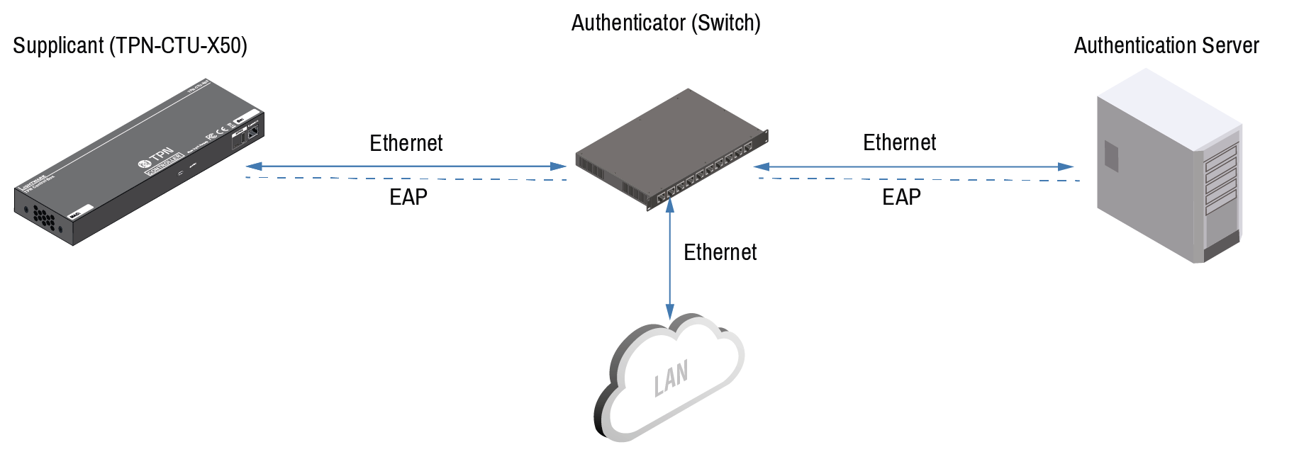
After the device passes the authentication process, the authentication server notifies the switch, allowing the client to access the LAN.
There are two available methods for 802.1x authentication in the TPN-CTU-X50 control unit:
▪EAP-MD5: This commonly used method authenticates by verifying MD5 (Message Digest 5) hash of a user password.
▪EAP-TLS: This method utilizes Public Key Infrastructure to authenticate with an authentication server. To communicate with the server, a certification authority (CA) certificate and a client-side certificate that is signed by a known certification authority are needed.
The CTU itself can act as a supplicant, but also as a route through which a BYOD device can reach the authenticator as a supplicant.
ATTENTION!This method authenticates the CTU, not the BYOD connected to the CTU. If you only want to authenticate the connected BYOD device and not the CTU, you do not need to activate 802.1x authentication in the CTU.
INFO:When updating the firmware of the CTU, sensitive information (passwords, keys etc.) on the authentication will not be downloaded into the backup file, but it will be retained in the device during the update.
5.10. WebSocket Service (WS, WSS)
DIFFERENCE:The feature is available only in the TPN-CTU-X50 control unit.
The CTU provides WS/WSS services on its 80 (for WS) and 443 (for WSS) ports to control the device with LW3 protocol commands.
The CTU can manage 18 connected clients in total simultaneously for WS (80), WSS (443), and LW3 (6107) ports.
The WebSocket connection is built up by HTTP handshake. After the connection is established, communication switches to a bi-directional WebSocket protocol for LW3 communication.
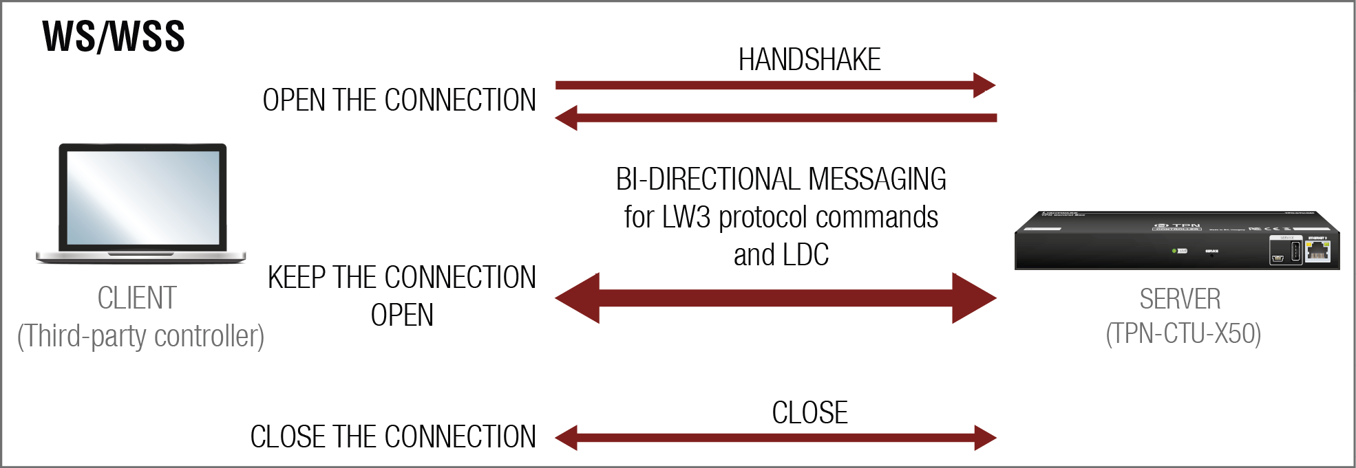
The main difference between HTTP and WS communication process is that HTTP closes the connection between the client and the server after one request-response pair, while WebSocket keeps the connection open. This feature allows real-time communication such as controlling the device with LW3 protocol commands. The WS functions are also available via WebSocket Secure (WSS).
5.11. Advanced Ethernet Security
DIFFERENCE:The feature is available only in the TPN-CTU-X50 control unit.
This feature is a port-based VLAN setting, which allows the user to decide which network(s) the Ethernet ports are connected to, and thus which network(s) the connected devices can use. This way the connected devices can be separated from the corporate network, increasing network security.
There are two options available, which are the following:
▪Transparent: this is the default mode, with the network openly used by Taurus and the BYOD devices. If you want to authenticate the connected BYOD through 802.1x, this option is not recommended.
▪Custom: the setting of any Ethernet port differs from the default property
INFO:Only one mode can be active at the same time.
5.11.1. Network Separation
DIFFERENCE:From FW version v1.3.0b2, Management network is introduced in CTU control unit.
The control unit supports two VLANs: the Default/AV network and the Management network. However, due to a topology limitation, both VLANs may currently operate under the same MAC address. This setup can lead to connectivity issues such as:
▪Packet Misrouting: Network traffic may be sent to the incorrect VLAN.
▪Loop and Congestion: Duplicate MAC addresses can cause loops or broadcast storms.
▪Device Inaccessibility: Difficulty in managing devices or maintaining network reliability.
To ensure stable operation and avoid connectivity conflicts, follow this practice:
On the switch, disable any ports or VLANs that are not actively in use. This reduces the chance of unintended traffic crossing between VLANs.
DEFINITION:Management network is a VLAN Membership setting that creates an Ethernet port that can be used to only connect to the CPU for controlling and updating purposes.
INFO:The illustrations have been simplified for easier understanding.
Update Restrictions
Only one CTU using MANAGEMENT network, while the other UCX TX or RX devices are only using presets without management enablnig to separate networks.
Restriction: To update the UCX devices in the AV VLAN, the updater has to be inside the AV VLAN network
Serial data communication can be established via the local RS-232 port (3-pole Phoenix connector).
5.12.1. Serial Port Diagram
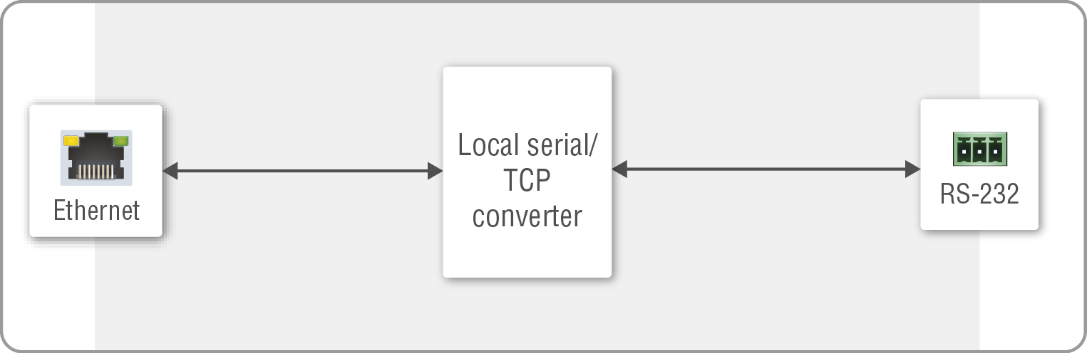
Serial port diagram of the TPN/OPTN series devices
The CTU works as an RS-232 bi-directional converter. The TCP signal is converted to RS-232 data and vice versa. TCP/IP port numbers are defined for serial ports (8001, 8002) for this purpose. If a command is coming from the Ethernet interface that is addressed to the port no. 8001, it will be transmitted to the Tx pin of the local RS-232 port (P1). That works in the opposite direction too, and the method is the same on the serial interface of the Ethernet port as well, but the serial message will be transmitted to all opened TCP sockets (if the TCP connection closed in the meantime, the message will not be transmitted). It can handle a maximum of 20 connections at the same time.
Disabling Serial over IP function disconnects the Serial/TCP converter from the Ethernet layer and the serial data won't be transmitted to the Ethernet network. This setting is available in the Lightware Device Controller software (in the Setting menu, Network tab), with REST API protocol command (Enabling/Disabling Network Service Port) or with LW3 protocol command (Enabling/Disabling Service Port).
The CTU can manage a maximum of 20 connected clients at the same time for each serial port.
Message Sending Function
Message sending function allows RS-232 command sending to a third-party (or a Lightware) device from the extender. Any format is acceptable (text, binary, hexadecimal,etc.), maximum message size is 100Kb. Escaping is unnecessary.
Serial message sending is possible by using HTTP Post with Lightware REST API.
»header: POST·http://<ip>/api/V1/MEDIA/SERIAL/<serial_port>/send·HTTP/1.1
»body: <message>
<serial_port> is P1 or P2.
The MP1 (CPU) is available over REST API interface. The MP1 (CPU) sends the message via the serial port to a third-party (or a Lightware) device. This is a one-way communication, the response will not be interpreted by the CPU. Consider using Serial over IP function instead if listening to a serial device is important.
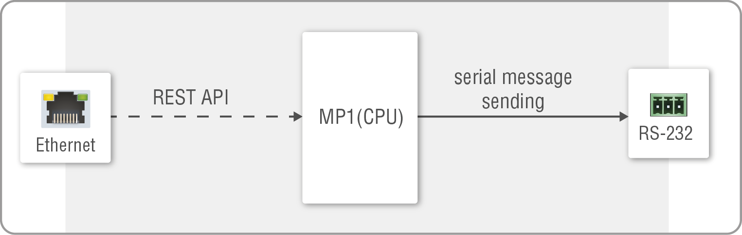
Port diagram of the serial message sending
For more details about the Lightware REST API, see the Lightware REST API Reference for CTU chapter.
INFO:The CTU can receive a serial message in a special way. When a message is sent from the switcher, the response from the connected device is accepted within 100 ms. The communication is closed after that time interval.
5.12.2. Serial Options - Example
External Controller Concept
The projector is turned on and off by the external system controller. The system controller has an internal REST API client, which is connected to the CTU. It sends a HTTP POST to the TPN-CTU-X50. The CTU sends a serial message over the P1 port to the Projector.
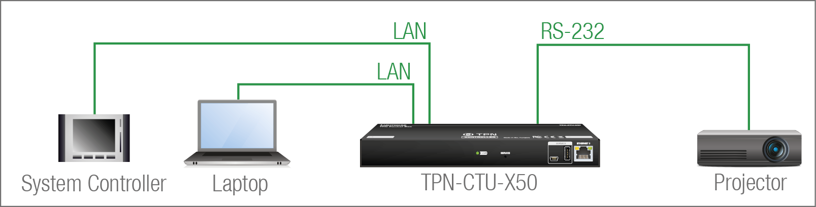
Security: When interpreting of the response from the projector is necessary, serial over IP port (8001 or 8002) can be enabled, in this case, the 8001 or 8002 ports are available from other devices too, and it makes the system unsecure.
Userscript feature supports the automatism in CTU device. The Userscript can be uploaded and run in the Settings Menu, System tab in the Lightware Device Controller (LDC) software. The script packages are created by Lightware, please contact your sales representative for help.
DIFFERENCE:GPIO port is available only in the TPN-CTU-X50 control unit.
The General Purpose Input/Output (GPIO) port is a multifunctional input/output interface to control the switcher or third-party devices and peripherals. You can establish the connection between the controller/controllable device and the CTU by the 8-pole Phoenix connector. The direction of the six pins is configurable independently from each other.
GPIO Options - Example
The ceiling lamp is turned off by Relay 1 and the projection screen is rolled down by Relay 2. Both relays are controlled by the GPIO port.
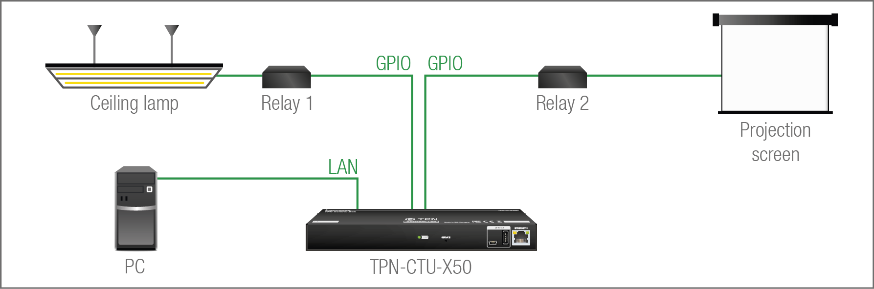
When the PC starts to play the video presentation, the signal is received over the HDMI input, so the GPIO pins send a signal to Relay 1 to open, which results in the lights being turned off. Furthermore, the GPIO pins also send a signal to Relay 2 to close and the projection screen is rolled down. When the presentation ends, signal ceases on the HDMI input, so the GPIO pins send a signal to Relay 1 to close, which results in the lights being turned off and send a signal to Relay 2 to open, so the projection screen returns to its enclosure.
Userscript feature supports the automatism in CTU device. The Userscript can be uploaded and run in the Settings Menu, System tab in the Lightware Device Controller (LDC) software. The script packages are created by Lightware, please contact your sales representative for help.
ATTENTION!Please always check the electrical parameters of the devices that you want to control. The maximum current of one GPIO pin is 30 mA, the maximum total current for the six pins is 180 mA.
DIFFERENCE:OCS port is available only in the TPN-CTU-X50 control unit.
OCS Application Example
When the occupancy sensor detects people in the meeting room, the CTU turns on the ceiling lamp.
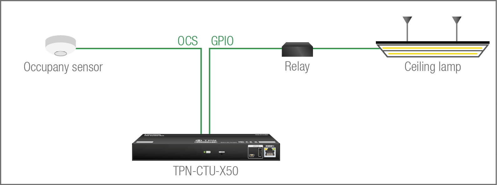
Userscript feature supports the automatism in CTU device. The Userscript can be uploaded and run in the Settings Menu, System tab in the Lightware Device Controller (LDC) software. The script packages are created by Lightware, please contact your sales representative for help.
In case of applying Leviton OCS (https://www.leviton.com/en/products/osc10-m0w), inserting a 1 kOhm external resistor between the 1st and the 3rd pins is necessary; for more information see the OCS Connector section.
5.15. Further Built-in Features
Device Cloning – Configuration Backup and Restore

The device (configuration) cloning of the CTU is a simple method that eliminates the need to repeatedly configure certain devices to have identical (non-factory) settings. If the devices are installed in the same type of system multiple times, then it is enough to set up only one device to fit the user’s needs and then copy those settings to the others, thus saving time and resources.
Cloning is possible between devices using the same firmware version. All LW3 settings and WelcomeScreen Image will be saved.
Please note that the clone file can be downloaded and uploaded via HTTP or HTTPS, so 80 or 433 port has to be enabled.
See more information about the settings in the Clone configuration section.
6. AV System Configuration - Step by Step
The TPN / OPTN System Configuration Guide can be downloaded from our website.
6.1. Dedicated Document for TPN / OPTN System Configuration
Check out the dedicated application notes for the TPN / OPTN system configuration what includes step-by-step instructions about system installation, configuration and customization as well. The document can be download from our website (PDF).
7. Software Control - Built-in Web
The built-in website of the Control Unit allows to connect to and control the device via a web browser. The range of the controlling features are the same as in the case of the Software Control - Lightware Device Controller.
System Requirements
Operating System: Microsoft Windows 10, Apple macOS, Linux.
Web Browser: Mozilla Firefox, Google Chrome, Apple Safari.
7.1. Establishing the Connection
ATTENTION!Please be sure that the computer is in the same network as the TPN / OPTN matrix. If the computer has multiple Ethernet connections (for example Wi-Fi and LAN connections are used simultaneously), you will need to know the IP address for the one that is used for controlling the CTU. #builtinweb #web
Step 1.Connect the matrix and the computer either via
▪Ethernet, with LAN patch cable, or
▪Ethernet, with LAN cross cable.
Step 2.Change to the desired IP settings if it needed.
Step 3.Type the IP address to the address bar of the web browser and press enter (the factory default is DHCP).
7.2. The Layout of the Built-in Web
The built-in web page allows the same controlling functions that are available via the Lightware Device Controller (LDC). Select a menu item on the right side; the default screen is the Crosspoint menu. See the detailed control features in the Software Control - Lightware Device Controller chapter.
ATTENTION!Please enable the pop-up windows in your browser; certain contents are only displayed in a new window.
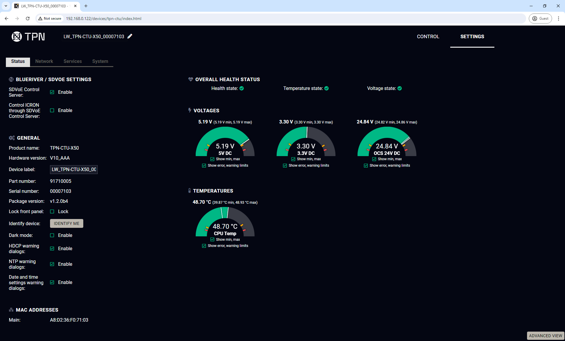
Built-in web view of the TPN-CTU-X50 in a Google Chrome web browser
8. Software Control - Lightware Device Controller
The device can be controlled by a computer through Ethernet interface with the Lightware Device Controller (LDC). The software can be installed on a Windows PC or macOS. The application and the User Manual can be downloaded from www.lightware.com.
INFO:After the installation the Windows and the macOS applications have the same look and functionality.
Minimum System Requirement
RAM: 1 GB
Minimum display resolution: 1280x720
Installation for Windows OS
Run the installer. If the User Account Control drops a pop-up message, click Yes.
During the installation you will be prompted to select the type of the installation: normal and the snapshot install:
|
Normal install |
Snapshot install |
|
Available for Windows and macOS |
Available for Windows |
|
The installer can update only this instance |
Cannot be updated |
|
Only one updateable instance can exist for all users |
More than one different version can be installed for all users |
Comparison of installation types
ATTENTION!Using the Normal install as the default choice is highly recommended.
Installation for macOS
Mount the DMG file by double clicking on it, and drag the LDC icon over the Applications icon to copy the program into the Applications folder. If you want to copy the LDC into another location, just drag the icon over the desired folder.
ATTENTION!Please check the firewall settings on the macOS device. LDC needs to be added to the exeptions of the blocked software for the proper operation.
Updating of LDC
Step 1.Run the application.
The Device Discovery window appears automatically, and the program checks the available updates on Lightware’s website and opens the update window if LDC updates are found.
The current and the update version number can be seen at the top of the window, and they are shown in this window even with the snapshot install.
The Update window can also be opened by clicking on the About  icon and the Update button.
Step 2.Set the desired update setting in the Options section.
▪If you do not want to check for the updates automatically, uncheck the circle that contains the green tick.
▪If you want to postpone the update, a reminder can be set with different delays from the drop down list.
▪If the proxy settings traverse the update process, set the proper values, then click on the OK button.
Step 3.Click on the Download update button to start the updating.
The updates can be checked manually by clicking on the Check now button.
8.2. Running the LDC
The common way to start the software is to double-click on the LDC icon. But the LDC can also be run by command line parameters as follows:
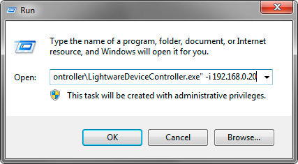
Launching of LDC in a Run window in Windows operating system
Connecting to a Device with Static IP Address
Format: LightwareDeviceController -i <IP_address>:<port>
Example: LightwareDeviceController -i 192.168.0.20:6107
The LDC is connected to a device with the indicated static IP address directly; the Device Discovery window is not displayed. When the port number is not set, the default port is used: 10001 (LW2 protocol - not supported by the CTU). For LW3 devices, use the 6107 port number.
Adjusting the Zoom
The window can be zoomed to a specific value to fit to the resolution of the desktop (higher/lower). '1' is the default value (100%).
Format: LightwareDeviceController -z <magnifying_value>
Example: LightwareDeviceController -z 1.2
ATTENTION!The last set value is stored and applied when LDC is started without a parameter.
8.3. Establishing the Connection
Step 1.Connect the device to a computer via Ethernet.
Step 2.Run the controller software; device discovery window appears automatically.
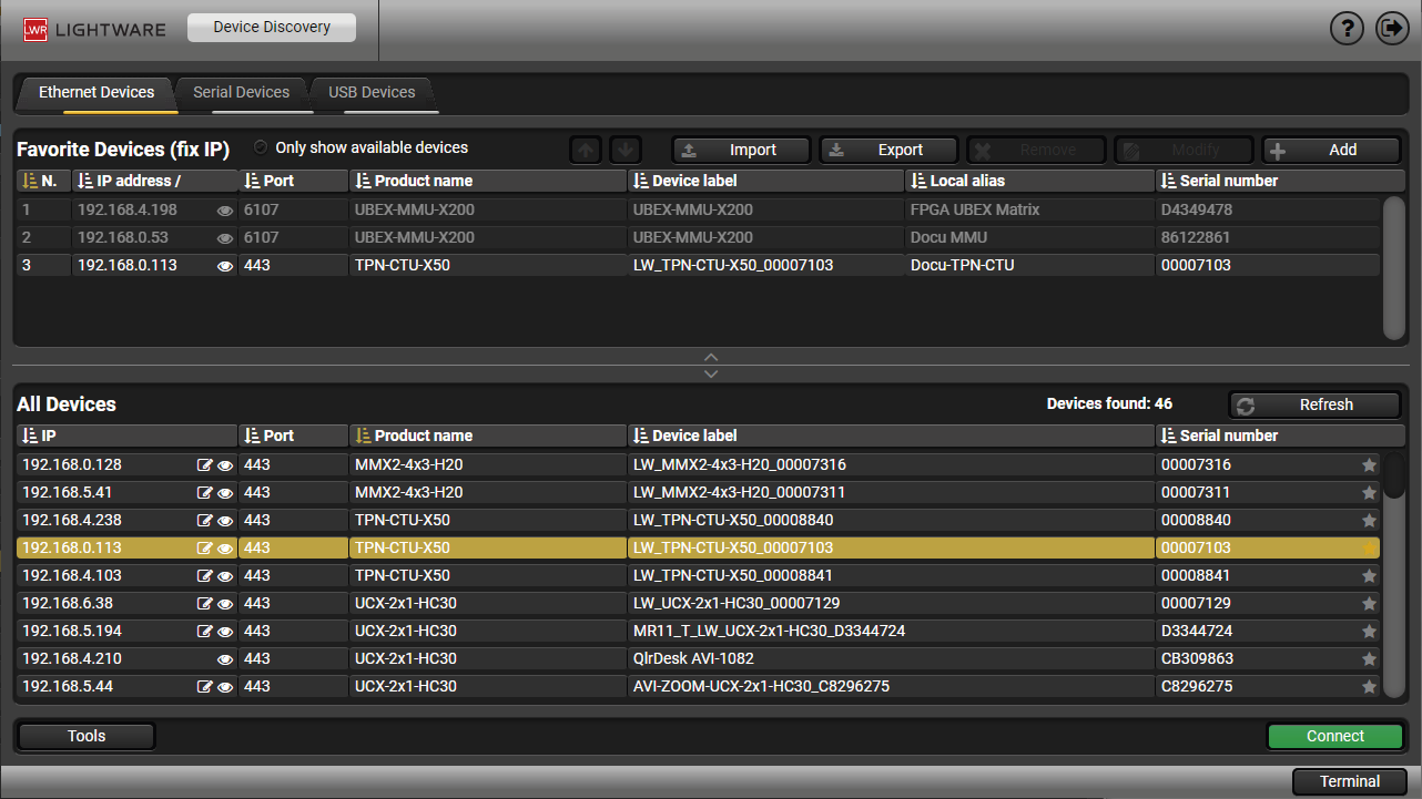
Device discovery window in LDC
The Ethernet tab consists of two lists. All devices list contains all Lightware devices that are available in the connected network (in the 255.255.0.0 subnet). However, there is no need to browse all the available devices as you can expand the list of Favorite devices with any Lightware device that is connected via Ethernet by any of the following ways:
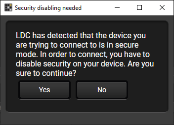
▪Mark the desired device with the  symbol in the All Devices list,
▪Press the Add button and add the device in the appearing window, or
▪Import the list of favorite devices that was exported previously.
When both the 6107 and 80 ports are disabled, only the secure 443 port remains open, the CTU appears in the all devices list with 443 port.
Double clicking on the device offers an option to open the other ports (80 and 6107) and use e.g. Lightware Device Controller software.

DIFFERENCE:This feature is available in LDC since v2.5.5.
Press the Add button; in the appearing window you can enter the IP address. The hostname of the desired device can be used instead, if it is supported. That allows setting a unique name to identify the device in a network. If the hostname is saved in this window and the IP address is changing, the device will still be available and connectible.
ATTENTION!The hostname connection feature does not work when the target device is accessed over VPN.
See more information about the hostname property in the Setting the Hostname section.
Import/Export the List of Favorite Devices
DIFFERENCE:This feature is available in LDC since v2.5.5.
The list of favorite devices can be exported/imported by the dedicated buttons (saved as *.JSON file). The list can be imported later (in another computer, too), but please note that the current list will be overwritten by the imported list.
Changing the IP Address 
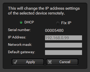
To modify the IP address settings quickly, it is not necessary to enter the device's settings/network menu, you can set them by clicking on the pencil icon beside the IP address.
You can only see the new settings in this window. The device needs a few seconds to apply the new settings. #ipaddress #dhcp
Identifying the Device 
Clicking on the icon results in the blinking of the status LEDs for 10 seconds. The feature helps find the device itself physically. #identifyme
8.4. Control Menu
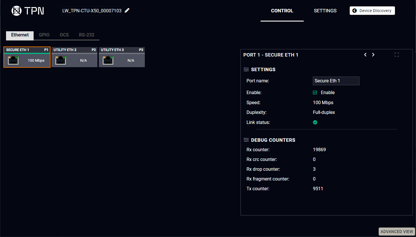
Ethernet tab in the Control menu
Three ports are displayed in the Ethernet settings: You can check the status of the Ethernet line by each port: the speed and the duplexity of the connection. #ethernet
The following settings are available for each port:
▪Rename the port
▪Enable / disable the port
8.4.2. GPIO
The GPIO port has 6 pins that operate at TTL digital signal levels and can be controlled by LDC or protocol commands. Select a GPIO pin under the Port settings section; the settings (pin direction and input level) are displayed on the port tiles as well. #gpio
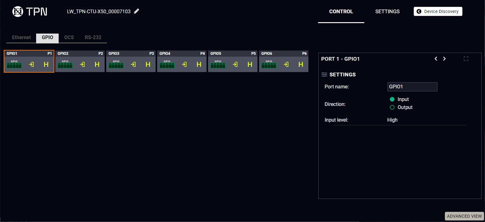
GPIO tab in the Control menu
INFO:Output level can be set only if the pin direction is set to Output. In case of input direction, the output level setting and the Toggle button is not available.
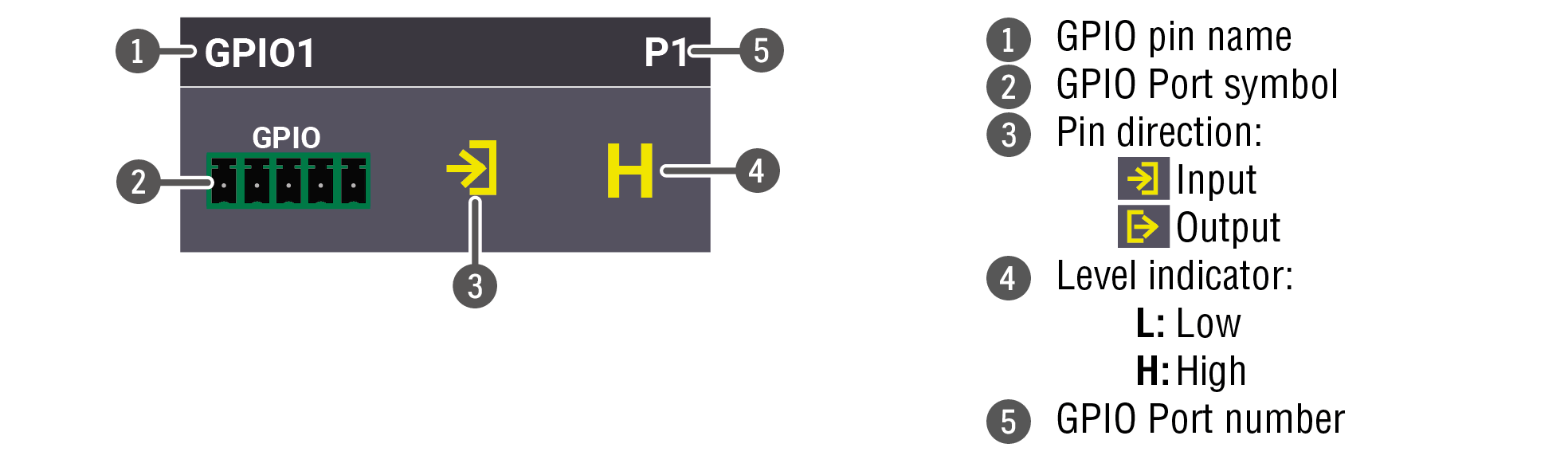
Interval (only for Output directon)
Interval section is designed for setting the chosen GPIO pin to the specified level for a specified time.Configure the Duration time and the Logic level of the desired value. Confirm by clicking on the Set interval button.
The OCS sensor has 3 pins, where the first pin is a 24V logic input. The default state is high. Different type of sensors exist: some send high level, some send low level to this input when the room is occupied. Active-high or active-low logic might be configured for this port in LDC to support them.
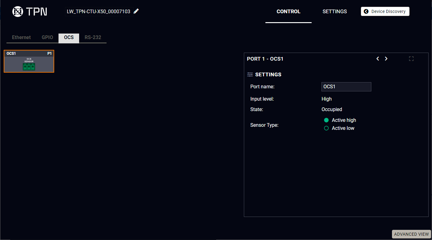
OCS tab in the Control menu
Input level refers to the current input signal level of the first pin.
State value can be free or occupied, depending on the Sensor type setting and the Input level (e.g. when the sensor type is Active high and the input value is high, the state reports 'Occupied').
Sensor type can be active high/active low, and this defines whether the low or high input level means the occupancy.
#ocs
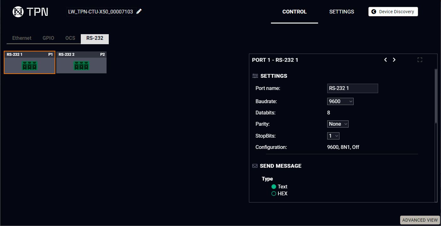
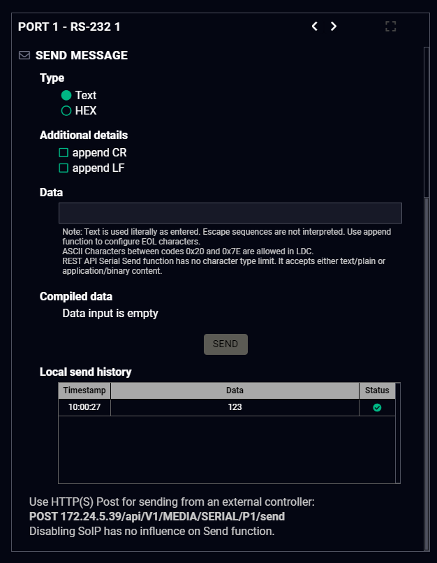
RS-232 tab in Control menu
The following settings and functions are available: #rs-232 #rs232 #serial
▪Baud rate: 9600, 14400, 19200, 38400, 57600, 115200;
▪Data bits: 8;
▪Parity: None, Odd, or Even;
Send Message Section
The serial message sending is achieved by Lightware REST API, and it can be in text or hexadecimal format. The CR/LF (Carriage Return/Line Feed) can be enabled optionally.
The most important hardware and software related information can be found on this tab: hardware and firmware version, serial numbers, MAC addresses, temperatures, and voltage information. Device label can be changed to a unique description by the Set button.
DIFFERENCE:Multiple MAC addresses generates in the CTU from firmware version v1.5.0 and the IP address of the device can be changed. See more details about it in the Device IP Change in the CTU during Firmware Update section.
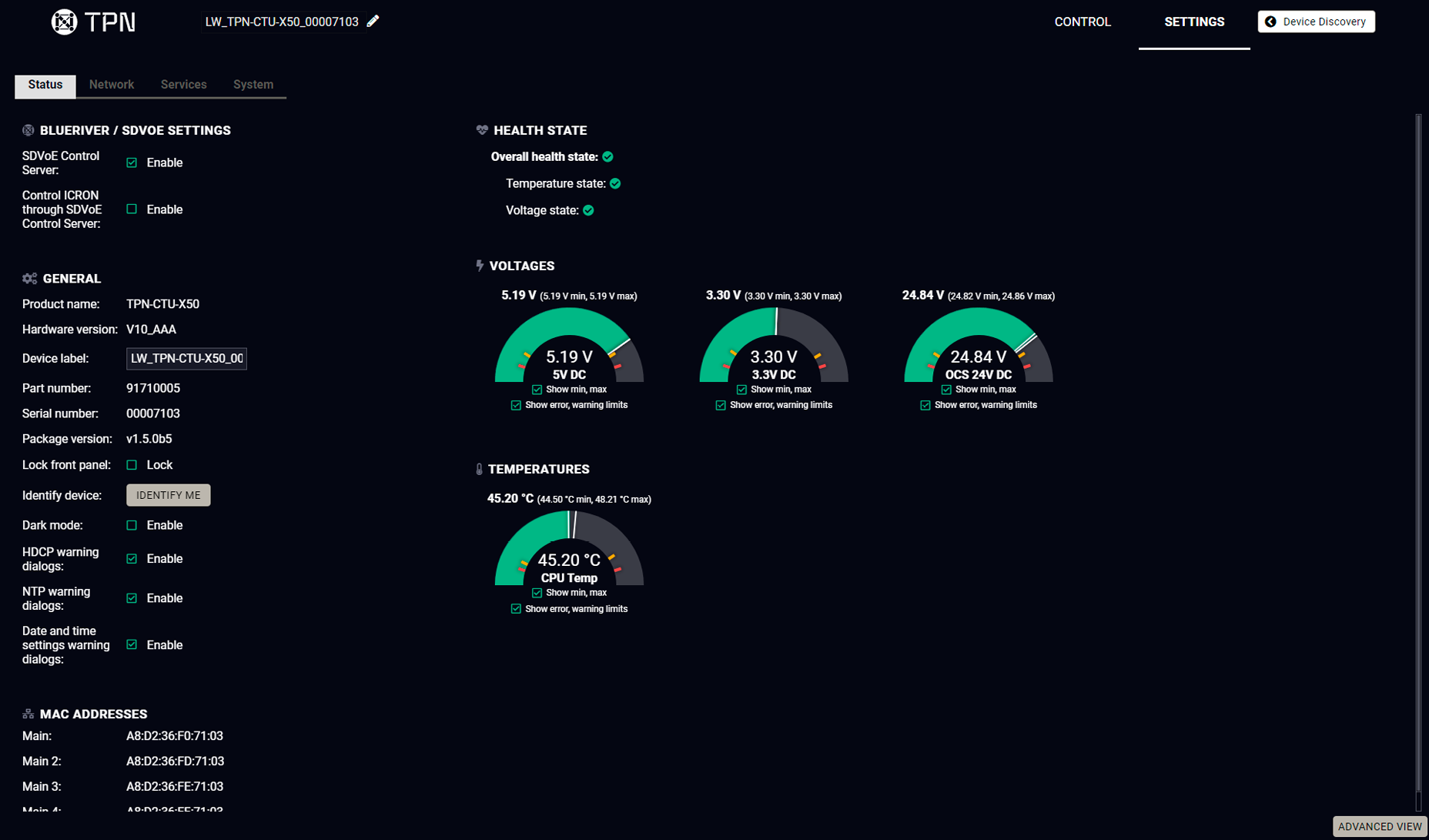
Status tab in the Settings menu
BlueRiver / SDVoE Settings
SDVoE Control Server: when it is enabled, the TPN-CTU-X50 control unit runs the built-in SDVoE Control Server to manage the TPN / OPTN series endpoint devices.
ATTENTION!Please make sure that only one BlueRiver Control Server operates in the system.
See the step-by-step description of the LARA module configuration for SDVoE in the AV System Configuration - Step by Step chapter.
Control Icron through SDVoE Control Server: when it is enabled, the USB KVM feature is managed by the SDVoE Control Server. If user wants to control the USB KVM feature by LARA module, this option is recommended to be disabled.
General Settings
You can disable the functionality of the front panel button by marking the Lock front panel option. Clicking on the Identify me button results in the blinking of the status and crosspoint LEDs in green for 10 seconds. The feature helps identify the device itself in the rack shelf.
Dark mode enable: When Dark mode is enabled, all LEDs on the unit are switched off (after 60 seconds by default) if no buttons are pressed. Pressing any button brings back the status info on the LEDs without performing the function of the button itself.
#darkmode #identifyme #buttonlock #lockbutton #devicelabel #label #producttype #firmwareversion #status #serialnumber #health #systemmonitor #mac
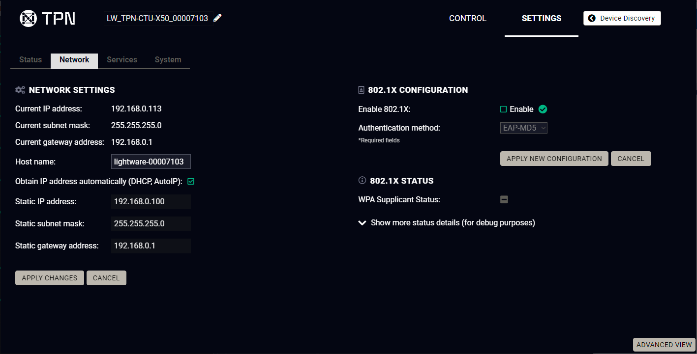
Network tab in the Settings menu
Network Settings
IP address and DHCP settings can be set on this tab. Always press the Apply settings button to save changes.
When the host name is modified, clicking on the Restart http(s) services button is also needed.
INFO:New certificate is generated after the hostname changing.
#hostname #8021x #security
802.1x Configuration
Authentication Process
You will find the 802.1x authentication section in the bottom left corner. #password
You can enable authentication by ticking in the Enable box. Once 802.1x authentication is enabled, you can choose the authentication method from the drop-down menu: EAP-MD5 or EAP-TLS.
When using EAP-MD5, authentication will require an Identity and a Password to gain access to the secure network.
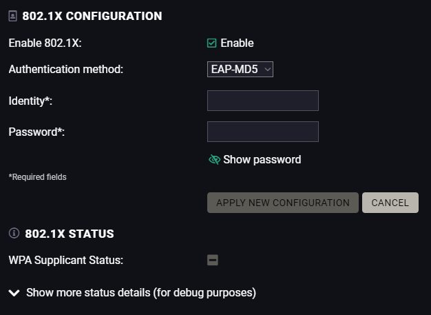
With EAP-TLS, you will also need CA and Client certificates, a Client Private Key, and a password for the Key.
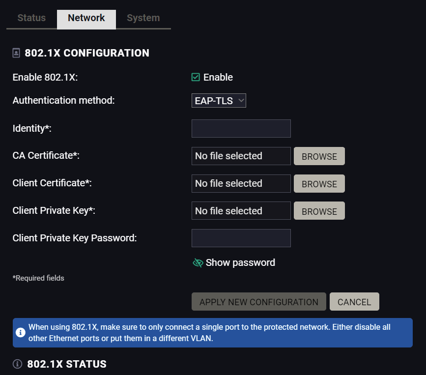
After entering every necessary information, click on the Apply new configuration button, and the authentication process starts.
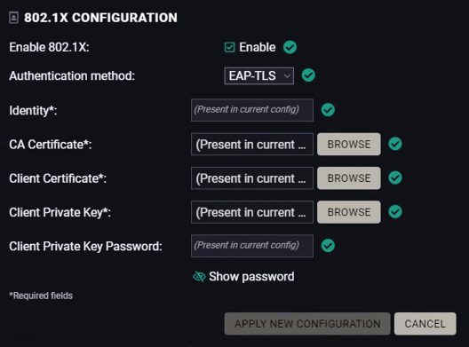
If every component is correct, the device will gain access to the secure LAN.
8.5.3. Service
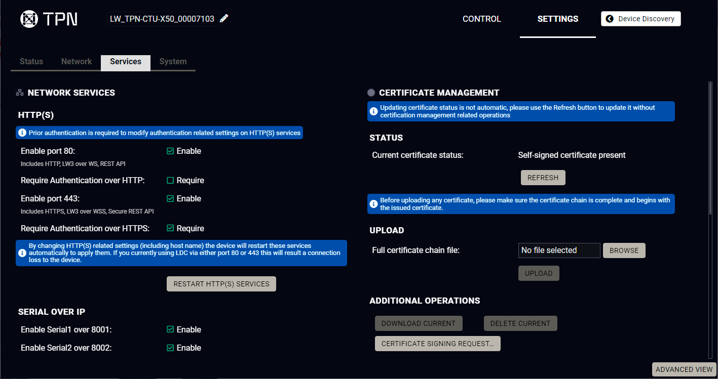
Service tab in the Settings menu
Network Services
HTTP/HTTPS
The TPN-CTU-X50 control unit provides HTTP/HTTPS server services on its 80 and 443 ports to make it accessible over WebSocket (WS), LW3 protocol, using Lightware Device Controller and REST API for device control (see the detailed list about the additional available features in the summary table of the Basic Network Security section).
HTTPS protocol encrypts the transferred data to keep it protected. For more details about the HTTPS, see the Encryption (HTTPS, WSS) section.
▪Enable/Disable HTTP/ HTTPS port: To ensure the secure data traffic, the HTTP port (80) can be disabled, and all of the information can be transferred via HTTPS (443 port).
80 or 443 ports is necessary to upload/download log and clone files so one of them should be opened to reach these functions.
ATTENTION!Please ensure proper time and date setting in the device because it affects the self-signed certificate (SSL) generation when using WSS or HTTPS. Improper time and date setting may lead to certificate rejection.
▪Require Authentication over HTTP/HTTPS: authentication helps limit the access to the device by setting a username (admin) and password. For more details, see the Basic Authentication section. No password is set by default, the authentication can be enabled after setting a password.
▪Restart HTTP(S) Services is required after the authentication settings changed.
Serial over IP
The signal route of the serial- IP transmission can be broken by disabling the serial over 8001 or 8002 port.For more details about the RS-232, see the Serial Interface section.
LW3
Enable LW3 over 6107: LW3 protocol commands, Ligthware Device Controller software.
WARNING!Lightware Device Controller software operates on 6107 port, when it is disabled, the CTU can be controlled only with protocol commands via http(s). Reset to factory default settings (Factory Reset (Service) Button for CTU) can re-enable the network interfaces.
LARA
LARA can be enabled by ticking in the box after enabling HTTPS and setting a password, which can be done below.
Credentials
The authentication password can be set here for HTTP/HTTPS ports. UTF-8 characters are allowed. Min length: 10 characters, max length: 100 characters. The password string can not be queried. The last 10 passwords given earlier is not engaged. #password
ATTENTION!If a wrong password is entered during login five times in a row, all login attempts are denied for 15 minutes.
New Password
ATTENTION!Authentication feature in TPN-CTU-X50 is not equal to the Cleartext login feature in the Advanced Control Pack in the TPS family extenders.
#network #http #https #security #authentication
You can upload certificates signed by the Certificate Authority (CA) to provide secure connection to the devices with the webLDC.
To download a Certificate Signing Request (CSR), follow these steps:
Step 1.Navigate to the Settings menu, Services tab and click on the Certificate Signing Request button.
Step 2.Enter the data required for the authentication process. It is important to provide all information related to your organization, because it will be used to verify your identity.
Step 3.Once all the necessary data has been entered, the file can be downloaded via the button in the bottom, and sent for signing.
Step 4.When the CA signs the certificate, it will create a .pem file, which then can be uploaded onto the device.
Step 5.After uploading, press the Refresh button in the Certificate Management section and the signed certificate shall be active.
Please be aware that the certificate will use the device's own private key and will not work for any other device. Each device must have its own certification file. #certificate
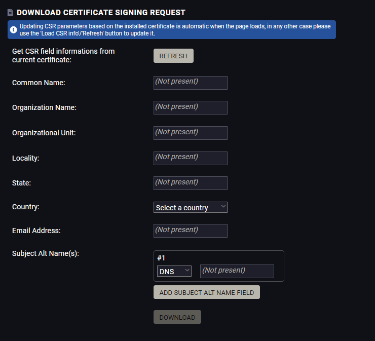
The certificate signing request form
|
Information |
Description |
Example |
|
Common Name |
The domain name you wish to secure. |
www.example.com |
|
Organization Name |
The legal name of the company or organization, any suffix included. |
Lightware Visual Engineering PLC |
|
Organizational Unit |
The name of the internal organizational department/division. |
IT |
|
Locality |
The name of the city, town, village etc. of the organization. |
Budapest |
|
State |
Province, region, county or state, not abbreviated. |
Pest county |
|
Country |
The country of the organization can be chose from the drop-down menu. |
Hungary |
|
Email Address |
The contact address of the certificate administrator or the IT department of the company. |
example@lightware.com |
In the Subject Alt Name(s) field you can enter additional information for more hosts to be certfied with one SSL file. The information type can be chosen from the drop down menu. You can have several Subject Alt Name fields.
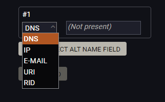
You can enter the following information in the Subject Alt Name field:
▪DNS
▪IP address
▪E-mail address
▪URI
▪RID
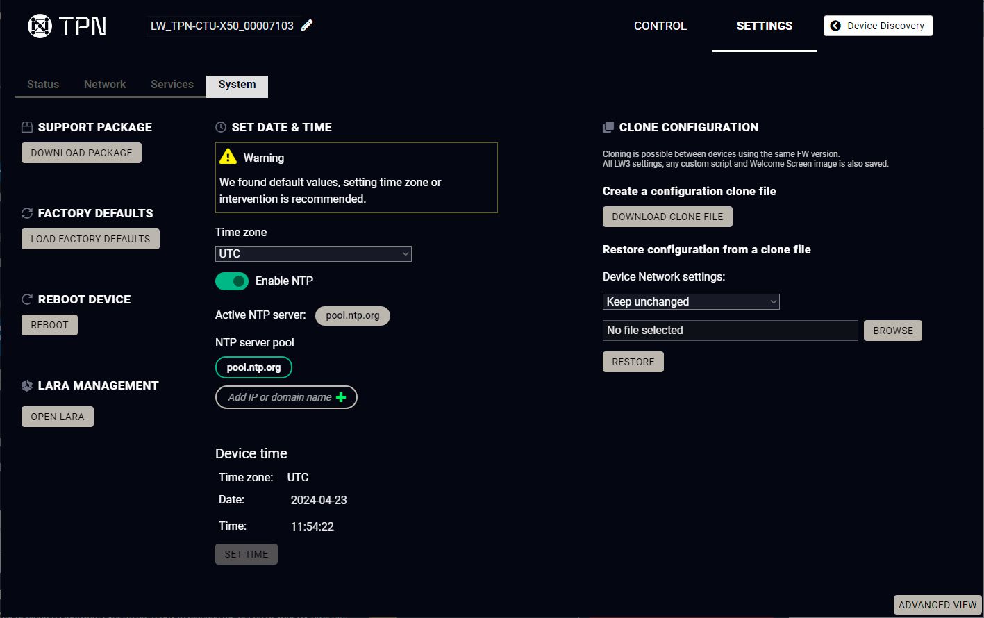
System tab in Settings menu
The following functions are available under System tab:
▪Support package - saving a log file of the device, helps during the troubleshooting process
▪Load factory defaults - recalling factory default settings and values. All factory default settings are listed in the Factory Default Settings section.
▪Reboot - rebooting the system.
▪Set time - (internal) clock of the switcher, which is used for logging events. #time #ntp
▪Pressing the Sync with Computer button is a quick and easy way to set the time. #factory #log #systemlog #reboot #restart
ATTENTION!Please ensure proper time and date setting in the device, because it affects the self-signed certificate (SSL) generation when using WSS or HTTPS. Improper time and date setting may lead to certificate rejection.
LARA management
The LARA interface can be opened by clicking on the Open LARA button. See the detailed instructions about the LARA configuration in the AV System Configuration - Step by Step section.
Clone configuration makes saving all the LW3 settings and welcome screen image and uploading them to another device possible.
ATTENTION!Please note that clone configuration function operates properly when the same firmware version is installed on the devices.
ATTENTION!If the device that the clone configuration is created on is password protected, the devices where this file is uploaded will also ask for a password. However, as passwords are not saved in the configuration file, the password is reset to admin.
Create a configuration clone file
Click on the Download Clone File button to save the setting to the computer.
Restore a configuration from a clone file
Step 1.Choose the desired network setting from the drop down menu:
▪Keep unchanged.
▪Restore from clone file (hostname will change, because the hostname property is also cloned from the original device and it can affect the generated certificates of the 443 port).
▪Set to DHCP mode.
▪Set to custom non-DHCP mode (in this case additional settings are required: IP Address, Subnet Mask, Gateway Address).
INFO:The network settings relate to Static or DHCP setting/ IP address/ Subnet mask/ Gateway address and the hostname property. Network service settings (enable http(s) ports, authentication etc.) will be always restored.
Step 2.Click on the Select file button to browse a clone file from the PC.
Step 3.The cloning process will start by clicking on Restore button.
See the entire list of the saved data in the backup file in the Content of the Backup File (Clone Configuration) section.
#configurationcloning #backup
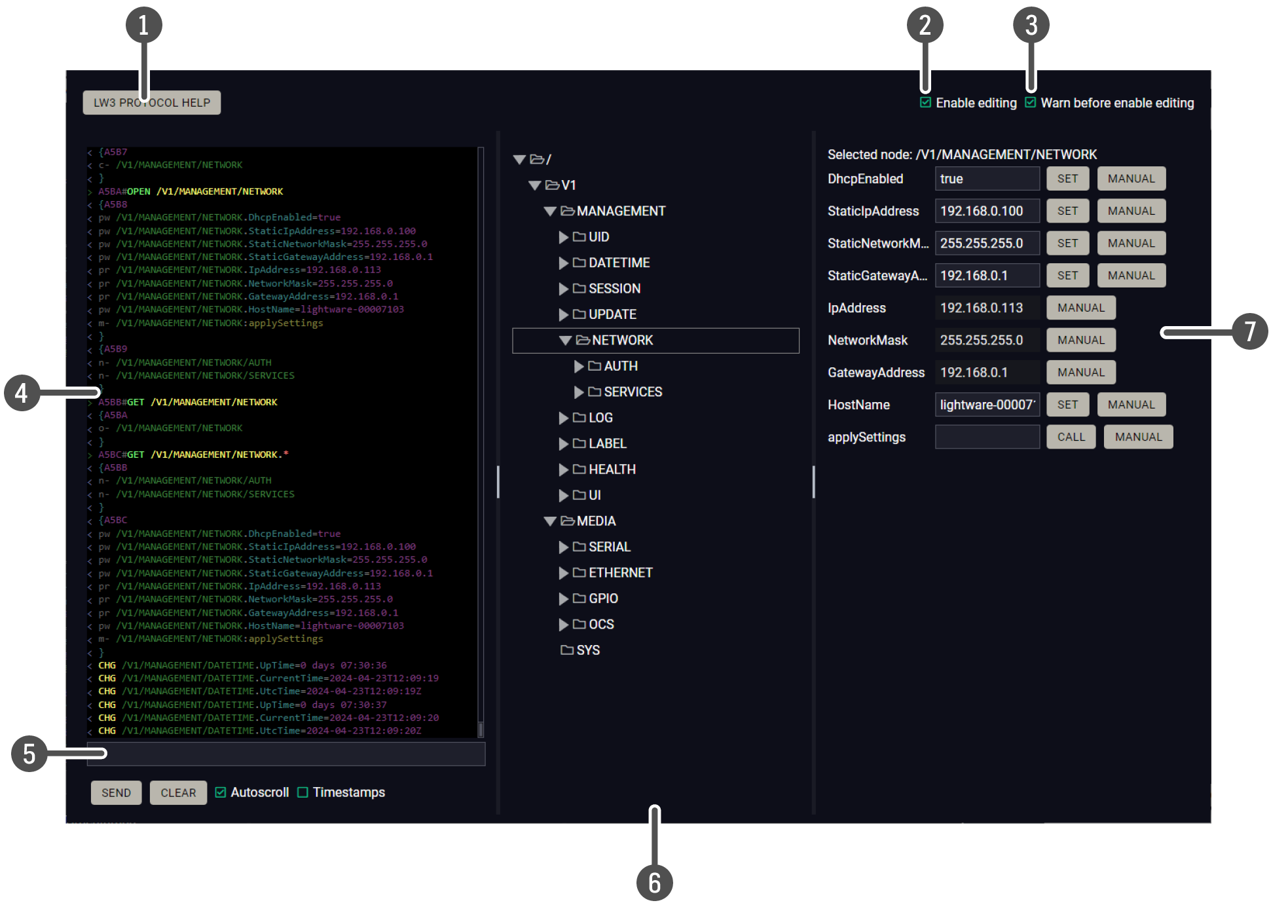
|
|
LW3 protocol help |
Pushing the button results in a help window opening, which describes the most important information about LW3 protocol commands in HTML format. |
|
|
|
Edit mode |
The default appearance is the read-only mode. If you want to modify the values or parameters, tick the option. You will be prompted to confirm your selection. |
|
|
|
Warning mode |
If this is checked, a warning window pops up when you enable Edit mode. |
|
|
|
Terminal window |
Commands and responses with time and date are listed in this window. Sent command starts with ‘>’ character, received response starts with ‘<’ character. The color of each item depends on the type of the command and response. The content of the window can be emptied by the Clear button. If the Autoscroll option is ticked, the list is scrolled automatically when a new line is added. |
|
|
|
Command line |
Type the desired command and execute it with the Send button. Clear all current commands and responses in the Terminal window by the Clear button. The commands typed in this line are not escaped automatically. |
|
|
|
Protocol tree |
LW3 protocol tree; select an item to see its content. |
|
|
|
Node list #advancedview #terminal |
Correspondent parameters and nodes are shown that are connected to the selected item in the protocol tree. The commands typed in these fields are escaped automatically. |
|
|
Manual button: |
Manual (short description) of the node can be called and displayed in the terminal window. |
||
|
Set button: |
Saves the value/parameter typed in the textbox. |
||
|
Call button: |
Calls the method, e.g. reloads factory default settings. |
||


9. Software Control - BlueRiver AV Manager
The TPN / OPTN System Configuration Guide can be downloaded from our website..
9.1. Introduction
BlueRiver AV Manager controls and manages AV distribution systems and endpoints that utilize Semtech’s BlueRiver technology platform, including all devices that are compatible with the Software Defined Video over Ethernet (SDVoE™) standard. The easy-to-deploy, highly intuitive software provides manufacturers, resellers and users of AV equipment featuring BlueRiver a free and easily customizable baseline AV control software that can be repackaged to deliver a wide variety of highly targeted user interface (UI) experiences. In addition to standard video and audio, the software can be used to establish and control Video Walls layouts. Basic USB HID and USB 2.0 routing and switching is also supported (mouse, keyboard, webcam, etc.). *
* Source: https://info.semtech.com/blueriver-av-manager
9.2. Dedicated Document for TPN / OPTN System Configuration
Check out the dedicated application notes for the TPN / OPTN system configuration what includes a detailed description about the BlueRiver AV Manager software and BlueRiver API Management.The document can be download from our website (PDF).
10. Lightware REST API Reference for CTU
The device can be controlled through standard HTTP(S) requests to ensure the control functions from web browsers or terminal program.
DIFFERENCE:This chapter refers to TPN-CTU-X50 control unit only.
10.1. Overview
The Lightware REST API is designed to provide a platform-free interface, where the TPN-CTU-X50 control unit can be controlled by HTTP requests. REST API is a software architectural style based on HTTP protocol, so it can be used via web browser, Node.js and terminal programs.
The TPN-CTU-X50 provides a REST API server where most of the LW3 commands are available (for more details, see the Lightware REST API vs. LW3 Protocol section).
Lightware devices can be controlled with LW3 protocol commands (for more details, see the LW3 Programmer's Reference), LW3 protocol consists of read-only, read-write properties and methods, which operate the same way as REST API GET/POST methods. This is not a new protocol, the LW3 tree structure is available via HTTP(s).
10.2. Instructions for the Terminal Application Usage
10.2.1. Web Browser Plugins
REST API interface can be easily accessed via a web browser's plugin, see the example below:
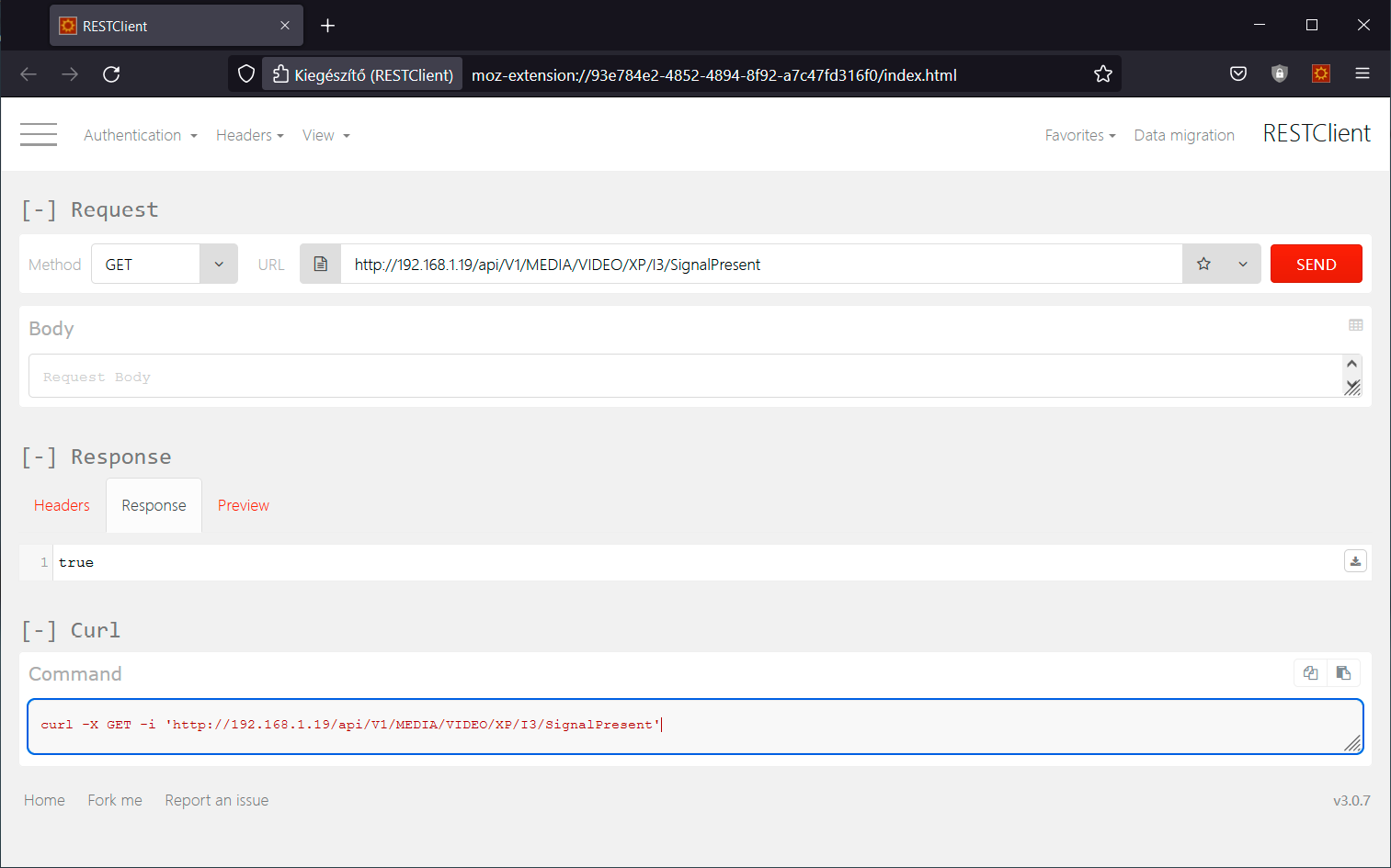
RESTClient plugin for Mozilla Firefox
10.2.2. Terminal Application
The REST API requests can be applied to the switcher using a terminal application. You need to install one of them to your control device, for example, Putty, CLI or Curl. #terminal
Curl
Curl is a command line tool that can also connect to the TPN-CTU-X50 REST SERVER and display communication in a terminal window. It supports data transferring with HTTP and HTTPS standards and handles the basic authentication (username and password) in Windows® and Linux operating systems. Multi-line commands are also accepted, so a script can be stored in a .txt file for future reference.
Check if the Curl package is installed on your system. Type into your console: curl. When the answer is 'curl: try 'curl --help' for more information', curl is installed.
Some web browser plugins (e.g. REST Client) display the curl version of the sent request.
Once the terminal window is opened, you can enter the commands. Some typical examples are listed in the following section.

REST API communication in a command line window
GET Command Example
Query the DHCP state
curl -i -X GET <ip>/api/<NodePath>/<PropertyName>
C:\Users>curl -i -X GET http://192.168.0.55/api/V1/MANAGEMENT/NETWORK/DhcpEnabled
HTTP/1.1 200 OK
X-Powered-By: Express
Content-Type: application/json; charset=utf-8
Content-Length: 5
ETag: W/"5-fLbvuYullyqbUJDcLlF/4U0SywQ"
Date: Sat, 13 May 2034 13:39:24 GMT
cache-control: max-age=86400,private
Server: lighttpd/1.4.56
true
POST Command Example 1.
Set the DHCP State
curl -X POST -i <ip>/api/<NodePath>/<PropertyName> --data <value>
C:\Users>curl -X POST -i http://192.168.0.55/api/V1/MANAGEMENT/NETWORK/DhcpEnabled --data false
HTTP/1.1 200 OK
X-Powered-By: Express
Content-Type: text/html; charset=utf-8
Content-Length: 5
ETag: W/"5-hg914ZeUflab5o9bn2uUeaPo3CI"
Date: Sat, 13 May 2034 13:48:09 GMT
cache-control: max-age=86400,private
Server: lighttpd/1.4.56
false
POST Command Example 2.
Set OCS Sensor
curl -X POST -i <ip>/api/<NodePath>/<PropertyName> --data <value>
C:\Users>curl -X POST -i http://192.168.0.55/api/V1/MEDIA/OCS/P1/SensorType --data Active low
HTTP/1.1 200 OK
X-Powered-By: Express
Content-Type: text/plain; charset=utf-8
Content-Length: 2
ETag: W/"2-nOO9QiTIwXgNtWtBJezz8kv3SLc"
Date: Sat, 13 May 2034 14:02:01 GMT
cache-control: max-age=86400,private
Server: lighttpd/1.4.56
Active low
POST Command with Basic Authentication Example
Set the DHCP State
curl --user <username>:<password> -X POST -i <ip>/api/<NodePath>/<PropertyName> --data <value>
C:\Users>curl --user admin:pwrd -X POST -H -i http://192.168.0.110/api/V1/MANAGEMENT/NETWORK/DhcpEnabled --data false
OK
HTTPS Command Example 2.
Set the DHCP State
curl -X POST -k -i <ip>/api/<NodePath>/<PropertyName> --data <value>
C:\Users>curl -X POST -k -i https://192.168.0.110/api/V1/MANAGEMENT/NETWORK/DhcpEnabled --data false
HTTP/1.1 200 OK
X-Powered-By: Express
Content-Type: text/plain; charset=utf-8
Content-Length: 2
ETag: W/"2-nOO9QiTIwXgNtWtBJezz8kv3SLc"
Date: Sun, 28 May 2034 12:28:20 GMT
cache-control: max-age=86400,private
Server: lighttpd/1.4.56
OK
10.3. Protocol Rules
10.3.1. Command Structure Example
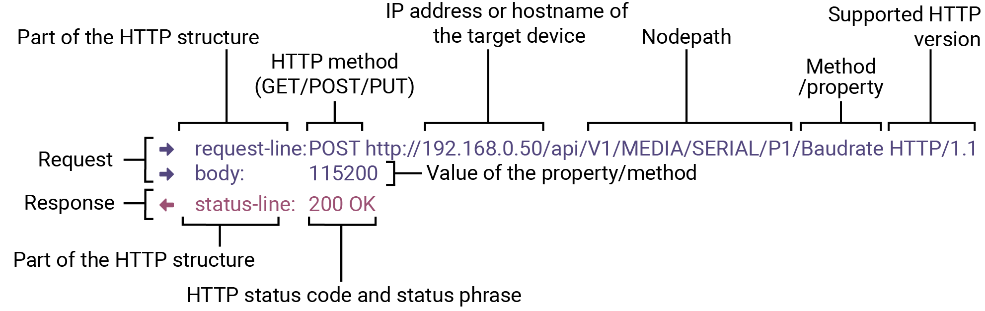
The examples below show how to apply the REST API in different environments:
Curl in Command Line Terminal
»curl -X POST -i http://192.168.0.50/api/V1/MEDIA/SERIAL/P1/Baudrate --data 115200
REST API Client in Mozilla
Method: POST
URL: http://192.168.0.50/api/V1/MEDIA/SERIAL/P1/Baudrate
Body content type: text/plain
Body: 115200
10.3.2. General Rules
▪All names and parameters are case-insensitive.
▪The methods, nodes and properties are separated by a slash (‘/’) character.
▪The node name consists of letters of the English alphabet and numbers.
▪All properties and methods are available HTTP(S) below /api as an URL.
▪The HTTP server is available on port 80, the HTTPS server is available on port 443.
▪GET / PUT/ POST methods are supported.
▪The request-line contains the IP address (or hostname) and the nodepath.
▪Arguments and property values should be given in the HTTP request’s body as a plain text.
▪REST API - LW3 converter does escaping automatically.
▪The node paths describe the exact location of the node, listing each parent node up to the root.
▪The supported HTTP protocol: standard HTTP/1.1
▪There is no maxiumum size or character length of the request.
10.3.3. Legend for the Control Commands
Command and Response – Example
»request-line: GET·<ip>/api/V1/MEDIA/GPIO/<port>/Input·HTTP/1.1
«body: <status code>
|
Format |
Description |
|
<ip> |
IP address or hostname of the target device |
|
<in> |
Input port number |
|
<out> |
Output port number |
|
<port> |
Input or output port number |
|
<loc> |
Location number |
|
<parameter> |
Variable defined and described in the command |
|
<expression> |
Batched parameters: the underline means that more expressions or parameters can be placed by using a semicolon, e.g. P1;P3 |
|
|
Sent request |
|
|
Received response |
|
· |
Space character |


Further, not listed <parameters> are defined at each command.
10.3.4. Lightware REST API vs. LW3 Protocol
All methods and properties of the LW3 tree structure appear below /api as a HTTP(s) URL. The separator character is always a slash (‘/’) character instead of point ('.') and colon (':'). The URL is case-insensitive.
Example
The LW3 property:
/V1/MEDIA/SERIAL/P1.Configuration
Available in REST API:
192.168.0.1/api/V1/MEDIA/SERIAL/P1/Configuration
192.168.0.1/API/v1/media/serial/p1/configuration
The following features are implemented only in REST API, but not in LW3 protocol:
The most important commands are listed in this chapter. Other commands can be inferred by the LW3 tree structure, where the read-only (eg. pr /V1/MEDIA/DATETIME.CurrentTime) and read-write properties
(pw /V1/MEDIA/NETWORK.HostName) can be listed. For more details about LW3 tree structure, see the LW3 Programmer's Reference section or the Advanced View Window.
10.3.5. Method Types
GET method can be used to get the value of a property. It works the same way as the LW3 GET command.
PUT/ POST Method
In this case, POST and PUT are equivalent, they are for modifying read-write properties and invoking methods. They replace LW3 SET and CALL command.
10.3.6. Supported Commands
Querying Property Value (GET)
The requested value is in the body of the response.
|
Protocol |
Command |
|
REST API |
|
|
Example |
|
|
LW3 |
»GET·/<NODEPATH>.<PropertyName> |
|
Example |
»GET /V1/MANAGEMENT/UID.SerialNumber |


Setting Property Value (SET)
The desired property value should be given as a plain text in the body of the request. The new value is in the body of the response.
|
Protocol |
Command |
|
REST API |
|
|
Example |
|
|
LW3 |
»SET·/<NODEPATH>.<PropertyName>=<new_value> |
|
Example |
»SET /V1/MANAGEMENT/LABEL.DeviceLabel=My_CTU |
Invoking Method (CALL)
The argument should be given in the body of the request.
|
Protocol |
Command |
|
REST API |
|
|
Example |
|
|
LW3 |
»CALL·/<NODEPATH>:<methodName>(<value>) |
|
Example |
»CALL /V1/MEDIA/GPIO/P1:interval(High) |
10.3.7. Not Supported Commands
Querying Node (GET)
|
Protocol |
Command |
Note |
|
REST API |
Not supported |
404 error code |
|
LW3 |
»GET·/<NODEPATH> |
|
|
Example |
»GET /V1/MEDIA/SERIAL |
|
Subscribing to a Node (OPEN)
|
Protocol |
Command |
Note |
|
REST API |
Not interpreted |
Not supported |
|
LW3 |
»OPEN·/<NODEPATH> |
|
|
Example |
»OPEN /V1/MEDIA/SERIAL |
Unsubscribing from a Node (CLOSE)
|
Protocol |
Command |
Note |
|
REST API |
Not interpreted |
Not supported |
|
LW3 |
»CLOSE·/<NODEPATH> |
|
|
Example |
»CLOSE /V1/MEDIA/SERIAL |
10.3.8. Status Codes, Error Messages
The standard HTTP response codes are defined to supply information about the response and the executed command like:
|
Error code |
Description |
|
|
200 |
OK |
Standard response for successful HTTP request. |
|
401 |
Unauthorized |
|
|
405 |
Method Not Allowed |
A request method is not supported for the requested resource. This is the error code when trying to modify a read-only property. |
|
404 |
Not Found |
Invalid nodepath or property name. |
|
406 |
Not Acceptable |
LW3 server error response for POST and PUT method, equals the following LW3 error codes: pE: an error for the property mE: an error for a method |
|
500 |
Internal Server Error |
All other errors (Lw3ErrorCodes_InternalError). |
10.3.9. Polling
Subscription and unsubscription features are not supported, they can be substituted with polling.
10.4. REST API Security
The REST API is designed with two security features: Authentication and Encryption. Both of them are optional and can be used independently of each other.
10.4.1. Authentication
Basic access authentication is designed to limit user access for the REST API server. It requires user authentication by using a password (username is fixed). #authentication #https #security
Follow the instructions below to set the password:
Step 1.Set the password.
»request-line: POST·<ip>/api/V1/MANAGEMENT/NETWORK/AUTHENTICATION/setPassword·HTTP/1.1
»body: <new_password>
Step 2.Enable the basic authentication on the chosen port (HTTP: 80 or HTTPS: 443).
»request-line: POST·<ip>/api/V1/MANAGEMENT/NETWORK/SERVICES/HTTP/AuthenticationEnabled·HTTP/1.1
»body: true
Step 3.Restart network services.
»request-line: POST·<ip>/api/V1/MANAGEMENT/NETWORK/SERVICES/HTTP/restart·HTTP/1.1
ATTENTION!The password will not be encrypted by this authentication mode, it remains accessible when the communication happens on HTTP.
For more details, see the Basic Authentication section.
10.4.2. Encryption (HTTPS)
There is no encryption when the REST API communication happens via HTTP, because the HTTP protocol is not encrypted. The REST API server is available via HTTPS on the 443 port. To avoid the data interception (e.g. stealing the password) HTTP should be disabled and HTTPS protocol used instead.
ATTENTION!Please ensure proper time and date setting in the CTU, because it affects the self-signed certificate (SSL) generation when using WSS or HTTPS. Improper time and date setting may lead to certificate rejection.
HTTPS does not guarantee that the communication is secure. Make sure that the client communicates with the server directly, without any third-party element in the communication route (Man-in-the-middle attack).
For more details, see the Encryption (HTTPS, WSS) section.
10.5.1. Setting the Device Label
INFO:The device label can be changed to a custom text in the Status tab of the LDC software.
Request and Response #devicelabel #label
»request-line: POST·http://<ip>/api/V1/MANAGEMENT/LABEL/DeviceLabel·HTTP/1.1
»body: <custom_name>
«status-line: 200·OK
«body: <custom_name>
The Device Label can be 49 characters long and ASCII characters are allowed. Longer names are truncated.
Example
»request-line: POST http://192.168.0.50/api/V1/MANAGEMENT/LABEL/DeviceLabel HTTP/1.1
»body: TPNController
«status-line: 200 OK
«body: TPNController
10.5.2. Restarting the Device
The CTU can be restarted – the current connections will be terminated.
Request and Response #reboot #restart
»request-line: POST·http://<ip>/api/V1/SYS/restart·HTTP/1.1
INFO:The body has to be empty, and the content type should be text/plain.
«staus-line: 200 OK
Example
»request-line: POST http://192.168.0.50/api/V1/SYS/restart HTTP/1.1
«status-line: 200 OK
10.5.3. Restoring the Factory Default Settings
Request and Response
»request-line: POST·http://<ip>/api/V1/SYS/factoryDefaults·HTTP/1.1
INFO:The body has to be empty, and the content type should be text/plain.
«status-line: 200 OK
Example
»request-line: POST http://192.168.0.50/api/V1/SYS/factoryDefaults HTTP/1.1
«status-line: 200 OK
The device is restarted, current connections are terminated, and the default settings are restored. See the complete list in the Factory Default Settings section. #factory
10.5.4. Querying the Firmware Package Version
Request and Response #firmwareversion
»request-line: GET·http://<ip>/api/V1/MANAGEMENT/UID/PACKAGE/Version·HTTP/1.1
«status-line: 200·OK
«body: <firmware_version>
Example
»request-line: GET http://192.168.0.50/api/V1/MANAGEMENT/UID/PACKAGE/Version HTTP/1.1
«status-line: 200 OK
«body: 1.5.0b5
Enable/disable the operation of the front panel buttons.
Request and Response
»request-line: POST·http://<ip>/api/V1/MANAGEMENT/UI/ControlLock·HTTP/1.1
»body: <lock_status>
«status-line: 200·OK
«body: <lock_status>
Parameters
|
Parameter |
Parameter description |
Values |
Value description |
|
<lock_status> |
Front panel button locking status |
None |
None: all functions of the front panel button are enabled. |
|
locked |
The front panel button is locked and can be unlocked by using this command. |
||
|
force locked |
The front panel button is locked and can be unlocked by using this command. |
Example
»request-line: POST http://192.168.0.50/api/V1/MANAGEMENT/UI/ControlLock HTTP/1.1
»body: force locked
«status-line: 200 OK
«body: Force locked
10.5.6. Setting the Current Time
Request and Response #time
»request-line: POST·http://<ip>/api/V1/MANAGEMENT/DATETIME/setTime·HTTP/1.1
»body: <current_time>
«status-line: 200·OK
«body: OK
Parameters
<current_time>: The new router time in ISO 8601 date time format.
Example
»request-line: POST http://192.168.0.50/api/V1/MANAGEMENT/DATETIME/setTime HTTP/1.1
»body: 2034-05-06T14:47:25
«status-line: 200 OK
«body: OK
10.5.7. Identifying the Device
Calling the method makes the status LEDs blink for 10 seconds. The feature helps to find the device physically.
Request and Response #identifyme
»request-line: POST http://<ip>/api/V1/MANAGEMENT/UI/identifyMe·HTTP/1.1
INFO:The body has to be empty, and the content type should be text/plain.
«status-line: 200 OK
Example
»request-line: POST http://192.168.0.50/api/V1/MANAGEMENT/UI/identifyMe HTTP/1.1
«status-line: 200 OK
10.5.8. Toggling the Dark Mode Setting
The LEDs of the device can be switched off, if their light could be annoying. In Dark mode, all the LEDs are switched off, except the LEDs of the RJ45 connectors (Ethernet and TPN input). #darkmode
Request and Response
»request-line: POST·http://<ip>/api/V1/MANAGEMENT/UI/DARKMODE/Enable·HTTP/1.1
»body: <mode_state>
«status-line: 200 OK
«body: <mode_state>
Parameters
If the <mode_state> parameter is true (or 1), the Dark mode function is enabled, if the parameter is false (or 0), the function is disabled.
Example
»request-line: POST http://192.168.0.50/api/V1/MANAGEMENT/UI/DARKMODE/Enable HTTP/1.1
»body: true
«status-line: 200 OK
«body: true
10.5.9. Setting the Delay of the Dark Mode
The Dark mode can be enabled right away, or after a certain time. Thus, the mode is enabled if no buttons are pressed for a while. Pressing any button brings back the status info on the LEDs without performing the function of the button itself. The delay time can be set by this command.
Request and Response
»request-line: POST·http://<ip>/api/V1/MANAGEMENT/UI/DARKMODE/Delay·HTTP/1.1
»body: <delay_time>
«status-line: 200 OK
«body: <delay_time>
Parameters
The <delay_time> parameter means seconds, and the default value is 0. If set to 0, no delay is applied, and the Dark mode can be enabled immediately by the DarkModeEnable property. This delay has an effect to the wakeFromDarkMode method as well.
Example
»request-line: POST http://192.168.0.50/api/V1/MANAGEMENT/UI/DARKMODE/Delay HTTP/1.1
»body: 10
«status-line: 200 OK
«body: 10
10.6. Ethernet Port Configuration
DIFFERENCE:Multiple MAC addresses generates in the CTU from firmware version v1.5.0 and the IP address of the device can be changed. See more details about it in the Device IP Change in the CTU during Firmware Update section.
10.6.1. Setting the DHCP State
ATTENTION!When you change a network property, the new value is stored, but the applySettings method must always be called to apply the new settings. When two or more network parameters are changed, the applySettings method is enough to be called once as a final step.
Request and Response #dhcp #network #ipaddress
»request-line: POST·http://<ip>/api/V1/MANAGEMENT/NETWORK/DhcpEnabled·HTTP/1.1
»body: <dhcp_status>
«status-line: 200 OK
«body: <dhcp_status>
Parameters
If the <dhcp_status> parameter is true, the current IP address setting is DHCP, if the parameter is false, the current IP address is static.
Example
»request-line: POST http://192.168.0.50/api/V1/MANAGEMENT/NETWORK/DhcpEnabled HTTP/1.1
»body: true
«status-line: 200 OK
«body: true
»request-line: POST http://192.168.0.50/api/V1/MANAGEMENT/NETWORK/applySettings HTTP/1.1
«status-line: 200 OK
«body: OK
INFO:The applySettings method will save and apply the new value and will reboot the device.
INFO:The current setting can be queried by using the GET Method.
10.6.2. Changing the IP Address (Static)
Request and Response
»request-line: POST·http://<ip>/api/V1/MANAGEMENT/NETWORK/StaticIpAddress·HTTP/1.1
»body: <IP_address>
«status-line: 200 OK
«body: <IP_address>
Example
»request-line: POST http://192.168.0.50/api/V1/MANAGEMENT/NETWORK/StaticIpAddress HTTP/1.1
»body: 192.168.0.100
«status-line: 200 OK
«body: 192.168.0.100
»request-line: POST http://192.168.0.50/api/V1/MANAGEMENT/NETWORK/applySettings HTTP/1.1
«status-line: 200 OK
«body: OK
INFO:The applySettings method will save and apply the new value and will reboot the device.
INFO:The current setting can be queried by using the GET Method.
10.6.3. Changing the Subnet Mask (Static)
Request and Response #ipaddress
»request-line: POST·http://<ip>/api/V1/MANAGEMENT/NETWORK/StaticNetworkMask·HTTP/1.1
»body: <netmask>
«status-line: 200 OK
«body: <netmask>
Example
»request-line: POST http://192.168.0.50/api/V1/MANAGEMENT/NETWORK/StaticNetworkMask HTTP/1.1
»body: 255.255.255.0
«status-line: 200 OK
«body: 255.255.255.0
»request-line: POST http://192.168.0.50/api/V1/MANAGEMENT/NETWORK/applySettings HTTP/1.1
«status-line: 200 OK
«body: OK
INFO:The applySettings method will save and apply the new value and will reboot the device.
INFO:The current setting can be queried by using the GET Method.
10.6.4. Changing the Gateway Address (Static)
Request and Response
»request-line: POST·http://<ip>/api/V1/MANAGEMENT/NETWORK/StaticGatewayAddress·HTTP/1.1
»body: <gw_address>
«status-line: 200 OK
«body: <gw_address>
Example
»request-line: POST http://192.168.0.50/api/V1/MANAGEMENT/NETWORK/StaticGatewayAddress HTTP/1.1
»body: 192.168.0.1
«status-line: 200 OK
«body: 192.168.0.1
»request-line: POST http://192.168.0.50/api/V1/MANAGEMENT/NETWORK/applySettings HTTP/1.1
«status-line: 200 OK
«body: OK
INFO:The applySettings method will save and apply the new value and will reboot the device.
INFO:The current setting can be queried by using the GET Method.
10.6.5. Applying Network Settings
Request and Response
»request-line: POST·http://<ip>/api/V1/MANAGEMENT/NETWORK/applySettings·HTTP/1.1
INFO:The body has to be empty, and the content type should be text/plain.
«status-line: 200 OK
«body: OK
Example
»request-line: POST http://192.168.0.50/api/V1/MANAGEMENT/NETWORK/applySettings HTTP/1.1
«status-line: 200 OK
«body: OK
All network settings that were changed are applied and the network interface restarts.
10.6.6. Setting the Hostname
The hostname is a property that can be used instead of the IP address when connecting to the device. It is also suitable for finding the device in the Device Discovery window of the LDC, see more details in the Add New Favorite Device section. Furthermore, it can be used to open the The Built-in Miniweb. If the IP address of the device is changing, the hostname can be used as a fixed property. #hostname
After hostname changing, restarting network services is required. New SSL certificate will be generated.
Request and Response
»request-line: POST·http://<ip>/api/V1/MANAGEMENT/NETWORK/HostName·HTTP/1.1
»body: <unique_name>
«status-line: 200 OK
«body: <unique_name>
Parameters
The <unique_name> can be 1-64 character(s) long and the following are allowed for naming: the elements of the English alphabet and numbers. Hyphen (-) and dot (.) are also accepted, except as last character.
Example
»request-line: POST http://192.168.0.50/api/V1/MANAGEMENT/NETWORK/HostName HTTP/1.1
»body: room-switcher
«status-line: 200 OK
«body: ServerRoom_Controller
10.7. Network Security
10.7.1. Enabling/Disabling Ethernet Port
Request and Response #ethernet
»request-line: POST·http://<ip>/api/V1/MEDIA/ETHERNET/<ethernet_port>/Enabled·HTTP/1.1
»body: <status>
«status-line: 200 OK
«body: <status>
Parameters
|
Identifier |
Parameter description |
Parameter values |
|
<ethernet_port> |
Ethernet port number |
P1-P3 |
|
<status> |
The port is enabled. The port is disabled. |
true false |
Example
»request-line: POST http://192.168.0.50/api/V1/MEDIA/ETHERNET/P1/Enabled HTTP/1.1
»body: false
«status-line: 200 OK
«body: false
10.7.2. Querying Network Service Port Number
Request and Response #http #https
»request-line: GET·http://<ip>/api/V1/MANAGEMENT/NETWORK/SERVICES/<port>/Port·HTTP/1.1
«status-line: 200·OK
«body: <port_num>
Parameters
|
Identifier |
Parameter description |
Parameter values |
|
<port> |
Port type |
HTTP HTTPS LW3 SERIAL1 SERIAL2 |
|
<port_num> |
Port number |
80 443 6107 8001 8002 |
Example
»request-line: GET http://192.168.0.50/api/V1/MANAGEMENT/NETWORK/SERVICES/HTTP/Port HTTP/1.1
«status-line: 200 OK
«body: 80
10.7.3. Enabling/Disabling Network Service Port
Request and Response
»request-line: GET·http://<ip>/api/V1/MANAGEMENT/NETWORK/SERVICES/<port>/Enabled·HTTP/1.1
»body: <status>
«status-line: 200 OK
«body: <status>
Parameters
|
Identifier |
Parameter description |
Parameter values |
|
<port> |
Port type |
HTTP HTTPS |
|
<status> |
The port is enabled. The port is disabled. |
true false |
Example
»request-line: POST http://192.168.0.50/api/V1/MANAGEMENT/NETWORK/SERVICES/HTTP/Enabled HTTP/1.1
»body: false
«status-line: 200 OK
«body: false
10.7.4. Querying the Username for Authentication
INFO:The CTU deals with one user for authentication and the username (admin) can not be changed.
Request and Response
»request-line: GET·http://<ip>/api/V1/MANAGEMENT/NETWORK/AUTH/USER1/Name·HTTP/1.1
«status-line: 200·OK
«body: admin
Example
»request-line: GET http://192.168.0.50/api/V1/MANAGEMENT/NETWORK/AUTH/USER1/Name HTTP/1.1
«status-line: 200 OK
«body: admin
10.7.5. Setting Password for Authentication
INFO:Due to security reasons, the password is not stored in any property, so it can not be queried. No password is set for default, setting a password before authorizing the authentication is necessary.
Request and Response #password
»request-line: POST·http://<ip>/api/V1/MANAGEMENT/NETWORK/AUTH/USER1/setPassword·HTTP/1.1
»body: <password>
«status-line: 200 OK
«body: <password>
Parameters
|
Identifier |
Parameter description |
Value description |
|
<password> |
User defined password for authentication. |
min. character length: 10 accepted characters: UTF-8 characters |
Example
»request-line: POST http://192.168.0.50/api/V1/MANAGEMENT/NETWORK/AUTH/USER1/setPassword HTTP/1.1
»body: #password12
«status-line: 200 OK
«body: #password12
10.7.6. Enabling Authentication
INFO:Set the password before enabling the authentication, because no password is set by default. Restart of the HTTP(S) services is required to apply the authentication settings.
Request and Response #authentication #security
»request-line: POST·http://<ip>/api/V1/MANAGEMENT/NETWORK/SERVICES/<port>/AuthenticationEnabled HTTP/1.1
»body: <status>
«status-line: 200 OK
«body: <status>
Parameters
|
Identifier |
Parameter description |
Parameter values |
|
<port> |
Port type |
HTTP HTTPS |
|
<status> |
Authentication enabled Authentication disabled |
true false |
Example
»request-line: POST http://192.168.0.50/api/V1/MANAGEMENT/NETWORK/SERVICES/HTTP/ AuthenticationEnabled HTTP/1.1
»body: false
«status-line: 200 OK
«body: false
10.8. Serial Port Configuration
INFO:Port numbering can be found in the Port Numbering section.
Request and Response #rs-232 #rs232 #serial
»request-line: POST·http://<ip>/api/V1/MEDIA/SERIAL/<serial_port>/Baudrate·HTTP/1.1
»body: <baudrate>
«status-line: 200 OK
«body: <baudrate>
Parameters
|
Identifier |
Parameter description |
Parameter values |
|
<serial_port> |
Serial port number |
P1-P2 |
|
<baudrate> |
Baud rate value |
9600, 19200, 38400, 57600, 115200 |
Example
»request-line: POST http://192.168.0.50/api/V1/MEDIA/SERIAL/P1/Baudrate HTTP/1.1
»body: 19200
«status-line: 200 OK
«body: 19200
Request and Response
»request-line: POST·http://<ip>/api/V1/MEDIA/SERIAL/<serial_port>/StopBits·HTTP/1.1
»body: <stopbits>
«status-line: 200 OK
«body: <stopbits>
Parameters
|
Identifier |
Parameter description |
Parameter values |
|
<serial_port> |
Serial port number |
P1-P2 |
|
<stopbits> |
Stop bit value |
1 2 |
Example
»request-line: POST http://192.168.0.50/api/V1/MEDIA/SERIAL/P1/StopBits HTTP/1.1
»body: 1
«status-line: 200 OK
«body: 1
Request and Response
»request-line: GET·http://<ip>/api/V1/MEDIA/SERIAL/<serial_port>/DataBits·HTTP/1.1
«status-line: 200·OK
«body: <databits>
Parameters
|
Identifier |
Parameter description |
Parameter values |
|
<serial_port> |
Serial port number |
P1-P2 |
|
<databits> |
DataBits value |
8 9 |
Example
»request-line: GET http://192.168.0.50/api/V1/MEDIA/SERIAL/P1/DataBits HTTP/1.1
«status-line: 200 OK
«body: 8
10.8.4. Parity Setting
Request and Response
»request-line: POST·http://<ip>/api/V1/MEDIA/SERIAL/<serial_port>/Parity·HTTP/1.1
»body: <parity>
«status-line: 200 OK
«body: <parity>
Parameters
|
Identifier |
Parameter description |
Parameter values |
|
<serial_port> |
Serial port number |
P1-P2 |
|
<parity> |
Parity value |
None Odd Even |
Example
»request-line: POST http://192.168.0.50/api/V1/MEDIA/SERIAL/P1/Parity HTTP/1.1
»body: None
«status-line: 200 OK
«body: None
10.8.5. Querying the Serial over IP Port Number
Request and Response
»request-line: GET·http://<ip>/api/V1/MEDIA/SERIAL/<serial_port>/SERIALOVERIP/Port·HTTP/1.1
«status-line: 200·OK
«body: <port_nr>
Parameters
|
Identifier |
Parameter description |
Parameter values |
|
<serial_port> |
Serial port number |
P1-P2 |
|
<port_nr> |
Serial over IP port number |
8001 8002 |
Example
»request-line: GET http://192.168.0.50/api/V1/MEDIA/SERIAL/P1/SERIALOVERIP/Port HTTP/1.1
«status-line: 200 OK
«body: 8001
10.8.6. Enabling the Serial over IP Port
Request and Response #rs232 #rs-232 #serial
»request-line: POST·http://<ip>/api/V1/MEDIA/SERIAL/<serial_port>/SERIALOVERIP/Enabled·HTTP/1.1
»body: <state>
«status-line: 200 OK
«body: <state>
Parameters
|
Identifier |
Parameter description |
Parameter values |
|
<serial_port> |
Serial port number |
P1-P2 |
|
<state> |
true false |
Example
»request-line: POST http://192.168.0.50/api/V1/MEDIA/SERIAL/P1/SERIALOVERIP/Enabled HTTP/1.1
»body: false
«status-line: 200 OK
«body: false
10.9.1. Sending a Message via RS-232
ATTENTION!Serial message sending is implemented only via Lightware REST API. This function is not available with LW3 protocol command. #message
Request and Response
»request-line: POST·http://<ip>/api/V1/MEDIA/SERIAL/<serial_port>/send·HTTP/1.1
»body: <message>
«status-line: 200 OK
Parameters
|
Identifier |
Parameter description |
Parameter values |
|
<serial_port> |
Serial port number |
P1-P2 |
|
<message> |
Serial message |
Any format is acceptable (text, binary, hexadecimal etc.), maximum message size is 100K. Escaping is unnecessary. |
Example
»request-line: POST http://192.168.0.50/api/V1/MEDIA/SERIAL/P1/send
»body: PWR0
«status-line: 200 OK
The 'PWR0' message is sent out via the P1 serial port.
INFO:The device can receive a serial message in a special way. When a message is sent from the device, the response from the connected device is accepted within 100 ms. The communication is closed after that time interval.
10.10. GPIO Port Configuration
10.10.1. Setting the Direction of a GPIO Pin
Request and Response #gpio
»request-line: POST·http://<ip>/api/V1/MEDIA/GPIO/<pin>/Direction·HTTP/1.1
»body: <dir>
«status-line: 200 OK
«body: <dir>
Parameters
|
Parameter |
Parameter description |
Value |
Value description |
|
<pin> |
GPIO pin number. |
P1-P6 |
|
|
<dir> |
The direction of the GPIO pin. |
Input |
input |
|
Output |
output |
Example
»request-line: POST http://192.168.0.50/api/V1/MEDIA/GPIO/P1/Direction HTTP/1.1
»body: Input
«status-line: 200 OK
«body: Input
10.10.2. Setting the Output Level of a GPIO Pin
Request and Response
»request-line: POST·http://<ip>/api/V1/MEDIA/GPIO/<pin>/Output·HTTP/1.1
»body: <state>
«status-line: 200 OK
«body: <state>
Parameters
|
Parameter |
Parameter description |
Value |
Value description |
|
<pin> |
GPIO pin number. |
P1-P6 |
|
|
<value> |
The output value of the GPIO pin. |
High |
high level |
|
Low |
low level |
Example
»request-line: POST http://192.168.0.50/api/V1/MEDIA/GPIO/P1/Output HTTP/1.1
»body: High
«status-line: 200 OK
«body: High
10.10.3. Setting the Output Level for a Specified Time
Request and Response
»request-line: POST·http://<ip>/api/V1/MEDIA/GPIO/<pin>/interval·HTTP/1.1
»body: <value>;<time>
«status-line: 200 OK
«body: <value>;<time>
Parameters
|
Parameter |
Parameter description |
Value |
Value description |
|
<pin> |
GPIO pin number. |
P1-P6 |
|
|
<value> |
The output value of the GPIO pin. |
High |
high level |
|
Low |
low level |
||
|
<time> |
Duration of the desired value in seconds. |
1-120 |
seconds |
Example
»request-line: POST http://192.168.0.50/api/V1/MEDIA/GPIO/P1/interval HTTP/1.1
»body: Low;1
«status-line: 200 OK
«body: OK
10.10.4. Toggling the Level of a GPIO Pin
The output level can be changed from low to high and from high to low by the command below.
Request and Response
»request-line: POST·http://<ip>/api/V1/MEDIA/GPIO/<pin>/toggle·HTTP/1.1
INFO:The body has to be empty, and the content type should be text/plain.
«status-line: 200 OK
«body: OK
Example
»request-line: POST http://192.168.0.50/api/V1/MEDIA/GPIO/P1/toggle HTTP/1.1
«status-line: 200 OK
«body: OK
10.11. OCS Port Configuration
10.11.1. Querying the Input Level of an OCS Pin
Request and Response #ocs
»request-line: GET·http://<ip>/api/V1/MEDIA/OCS/P1/InputLevel·HTTP/1.1
«status-line: 200·OK
«body: <value>
Parameters
|
Parameter |
Parameter description |
Value |
Value description |
|
<value> |
The input value of the OCS pin. |
High |
high level |
|
Low |
low level |
Example
»request-line: GET http://192.168.0.50/api/V1/MEDIA/OCS/P1/InputLevel HTTP/1.1
«status-line: 200 OK
«body: Low
10.11.2. Setting the Sensor Type
Request and Response
»request-line: POST·http://<ip>/api/V1/MEDIA/OCS/P1/SensorType·HTTP/1.1
»body: <sensor_type>
«status-line: 200 OK
«body: <sensor_type>
Parameters
|
Parameter |
Parameter description |
Value |
Value description |
|
<sensor_type> |
It defines whether the low or high input level means the occupancy. |
Active low |
Occupancy status is 'Occupied' when the input level is low. |
|
Active high |
Occupancy status is 'Occupied' when the input level is high (default value). |
Example
»request-line: POST http://192.168.0.50/api/V1/MEDIA/OCS/P1/SensorType HTTP/1.1
»body: Active low
«status-line: 200 OK
«body: Active low
10.11.3. Querying the Reported OCS State
Request and Response
»request-line: GET·http://<ip>/api/V1/MEDIA/OCS/P1/State·HTTP/1.1
«status-line: 200·OK
«body: <status>
Parameters
|
Parameter |
Parameter description |
Value |
Value description |
|
<status> |
It reports the occupancy state of the room depending on the sensor type. |
Free |
When the SensorType=Active high and the Inputlevel=Low or when SensorType=Active low and Inputlevel=High |
|
Occupied |
When the SensorType=Active high and the Inputlevel=High or when SensorType=Active low and Inputlevel=Low |
Example
»request-line: GET http://192.168.0.50/api/V1/MEDIA/OCS/P1/State HTTP/1.1
«status-line: 200 OK
«body: Free
10.12. Updating the Device via REST API
10.12.1. Querying the Update REST API Version
Request and Response #firmwareupdate #update
»request: GET·http://<ip>/api/V1/MANAGEMENT/UPDATE/Version
«response: <standard_response>
«body: <major>.<minor>
Parameters
|
Parameter |
Parameter description |
Values |
Value description |
|
<ip> |
The IP address of the device separated with dots. |
e.g.: 192.168.0.110 |
|
|
<standard_response> |
Standard HTTP response |
200 OK |
The request has succeeded. |
|
400 Bad request |
The request cannot be processed. |
||
|
<major> |
REST API major version number |
||
|
<minor> |
REST API minor version number |
Example
»request: GET http://192.168.0.11/api/V1/MANAGEMENT/UPDATE/Version
«response: 200 OK
«body: 1.1
10.12.2. The Updating Process
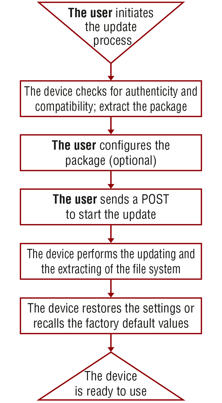
The API allows the device to update itself with an LFP2 FW package. This new approach means there is no need to run a software on the connected PC (in case of LDU2) for updating the Lightware device.
The Updating Steps
1.The User uploads the package to a dedicated URL.
=The package is being unpacked during the uploading process.
=The package is checked by the device to see if they are compatible with each other.
2.The User can set the uploaded package.
=The factory default settings can be recalled (this is the default setting of the package) or the current settings of the device can be restored (optional).
3.The User starts the self-updating process by sending a POST method.
=The device performs the operations in connection with the update (e.g. file system replacement).
=The device restores the previous settings to the new system, if it was set to.
4.The device is ready to use.
10.12.3. Uploading the Package
This step may take up to one or two minutes to finish as the size of the LFP2 package is approx. 100-150 MB (depends on the device and FW version).
Request and Response
»request: POST·http://<ip/host>/api/V1/MANAGEMENT/UPDATE/Package
»body: <LFP2 file>
»content-type: application/octet-stream
«response: <standard_response>
«body: <message>
Parameters
|
Parameter |
Parameter description |
Values |
Value description |
|
<ip/host> |
The IP address or the host name of the device. |
e.g.: 192.168.0.110, myDevice |
|
|
<standard_response> |
Standard HTTP response |
200 OK |
<message>: OK The request has succeeded; the whole package is extracted and the basic checks are done. |
|
400 Bad request |
<message>: Package incompatible: Incompatible partnumber: [...] The request cannot be processed; error during the uploading/checking. e.g. the package is not compatible with the device. The <message> is in text/plain format. |
||
|
500 Internal Server Error |
<message>: Socket timeout The package uploading was not successful. Please try it again. |
Example
»request: POST http://192.168.0.114/api/V1/MANAGEMENT/UPDATE/Package
»body: (the LFP2 file)
«response: 200 OK
«body: OK
10.12.4. Configuration Parameters – Keep the Current Settings
This is an optional step that allows keeping the current settings of the device. The default setting of an update is to recall the factory default values. If you want to keep the current settings of the device, delete the 'dofactoryreset' file from the uploaded package as follows:
Request and Response
»request: DELETE·http://<ip/host>/api/V1/MANAGEMENT/UPDATE/CONFIG/dofactoryreset
«response: <standard_response>
«body: <message>
Parameters
|
Parameter |
Parameter description |
Values |
Value description |
|
<ip/host> |
The IP address or the host name of the device. |
e.g.: 192.168.0.110, myDevice |
|
|
<standard_response> |
Standard HTTP response |
200 OK |
"Deleted" |
|
405 Method not allowed |
LFP2 package was not uploaded to the device. |
||
|
500 Internal Server Error |
The file does not exist in the uploaded package (e.g. it was deleted previously). Continue the update process. |
Example
»request: DELETE http://192.168.0.114/api/V1/MANAGEMENT/UPDATE/CONFIG/dofactoryreset
«response: 200 OK
«body: Deleted
10.12.5. Executing the Update
The command is for installing the uploaded package in place of the current system. This step may take up to 7 minutes.
Request and Response
»request: POST·http://<ip/host>/api/V1/MANAGEMENT/UPDATE/update
»body: <payload>
»content-type: text/plain
«response: <standard_response>
«body: <message>
Parameters
|
Parameter |
Parameter description |
Values |
Value description |
|
<ip/host> |
The IP address or the host name of the device. |
e.g.: 192.168.0.110, myDevice |
|
|
<payload> |
optional |
force |
The update can be forced to run in Package incompatible error state, but the security check cannot be bypassed (Package untrusted state). |
|
<standard_response> |
Standard HTTP response |
200 OK |
The request has succeeded; the update process finished successfully. |
|
400 Bad request |
The request cannot be processed. it may happen that the uploaded package is not compatible with the device (Package incompatible error state) and the force payload was not used. |
ATTENTION!Please note that running a forced update can make the device inoperable.
Example
»request: POST http://192.168.0.114/api/V1/MANAGEMENT/UPDATE/update
«response: 200 OK
«body: OK
When the 'force' payload is used:
»request: POST http://192.168.0.114/api/V1/MANAGEMENT/UPDATE/update
»body: force
»content-type: RAW (JSON)
«response: 200 OK
«body: OK
10.12.6. Querying the State of the Updating Process
This command is for querying the current state of the updating process.
Request and Response
»request: GET·http://<ip/host>/api/V1/MANAGEMENT/UPDATE/Status
«response: <standard_response>
«body: <message>
Parameters
|
Parameter |
Parameter description |
Values |
Value description |
|
<ip/host> |
The IP address or the host name of the device. |
e.g.: 192.168.0.110, myDevice |
|
|
<standard_response> |
Standard HTTP response |
200 OK |
The request has succeeded. <message> states: Idle: not active, update has not started yet. Package uploading: updating and checking is in progress. Package ready: uploading is done, checking is successful. |
|
400 Bad Request |
The request cannot be processed. <message> states: Package incompatible: the uploaded package is not compatible with the device. Package untrusted: the uploaded package is not secure. Failed: the update is not successful. |
INFO:Please note that while the new firmware is being programmed in the device, it cannot send a response for a request. Thus the current state cannot be requested either.
After the firmware update is finished successfully, the device would send the 'Idle' response when requesting its status with this command.
Example
»request: GET http://192.168.0.114/api/V1/MANAGEMENT/UPDATE/Status
«response: 200 OK
«body: Package uploading
10.13. Lightware REST API - Quick Summary
11. LW3 Programmer's Reference
The device can be controlled through Lightware 3 (LW3) protocol commands to ensure the compatibility with other Lightware products. The supported LW3 commands are described in this chapter.
DIFFERENCE:This chapter refers to the TPN-CTU-X50 control unit only.
11.1. Overview
The Lightware Protocol #3 (LW3) is implemented in almost all new Lightware devices (matrix switchers, signal extenders and distribution amplifiers) since 2012. The protocol is ASCII-based and all commands are terminated with a carriage return (Cr, ‘\r’) and line feed (Lf, ‘\n’) pair. It is organized as a tree structure that provides outstanding flexibility and user-friendly handling with ‘nodes’, ‘properties’ and ‘methods’. The Advanced View Window of the Lightware Device Controller (LDC) software is the perfect tool for browsing and learning how the LW3 protocol can be used in practice.
11.2. Instructions for the Terminal Application Usage
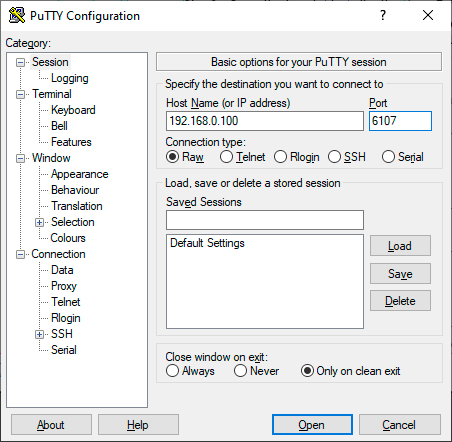
Terminal Application
The LW3 protocol commands can be applied to the CTU using a terminal application. You need to install one of them to your control device, for example Putty or CLI. #terminal
Establishing Connection
Follow the steps for establishing connection to the device:
Step 1.Connect the CTU to a LAN over Ethernet.
Step 2.Open the terminal application (e.g. Putty).
Step 3.Add the IP address of the CTU (the default is DHCP) and the port number (6107).
Step 4.Select the Raw connection type, and open the connection.
Once the terminal window is opened, you can enter the LW3 protocol commands, which are listed in the following sections.
11.3. Websocket (WS) or Secured Websocket (WSS) Usage
TPN-CTU-X50 control unit provides WS/WSS services on its 80 (for WS) and 443 (for WSS) ports to control the device with LW3 protocol commands. For more details about the websocket, see the WebSocket Service (WS, WSS) section.
The LW3 node tree is available after opening a session with the device on the following path:
▪ws://<ip>/lw3
▪wss://<ip>/lw3
WebSocket Client Application
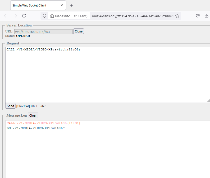
Establishing the Connection
Follow the steps to establish connection to the switcher:
Step 1.Connect the device to a LAN over Ethernet.
Step 2.Open the websocket client (e.g. Simple websocket Client).
Step 3.Add the IP address of the device (default: DHCP): ws://<ip>/lw3 or wss://<ip>/lw3
Step 4.Press the open/connect button.
Step 5.Once connected, enter a message and press the Send button.
Step 6.Press the Close/Disconnect button to end the session.
11.4. Protocol Rules
11.4.1. LW3 Tree Structure and Command Structure (examples)
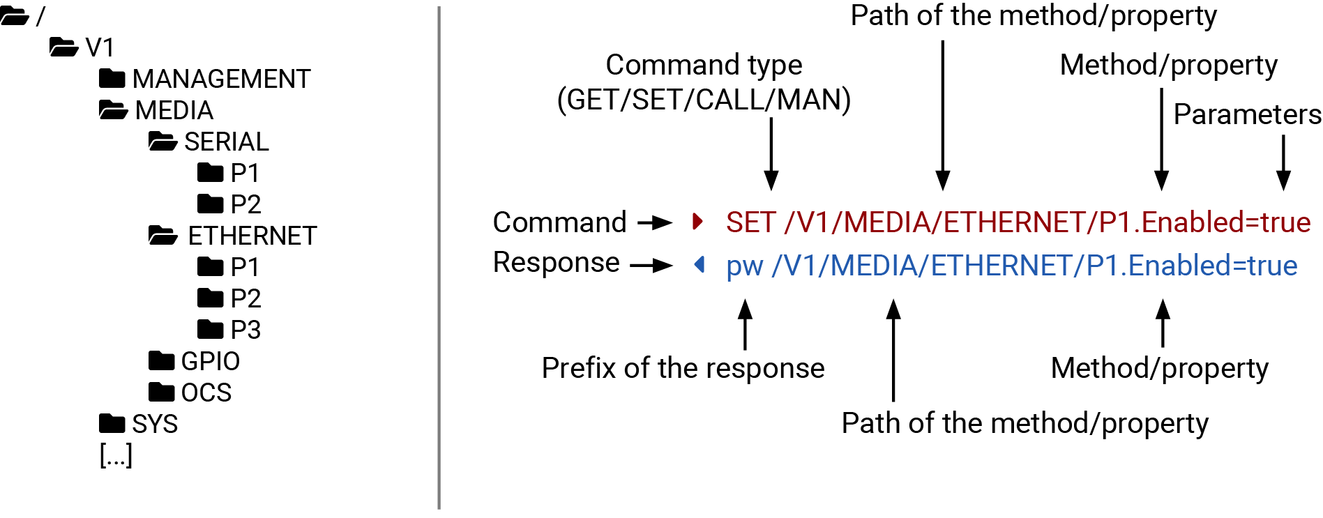
11.4.2. General Rules
▪All names and parameters are case-sensitive.
▪The nodes are separated by a slash (‘/’) character.
▪The node name can contain the elements of the English alphabet and numbers.
▪Use the TCP port no. 6107 when using LW3 protocol over Ethernet.
▪The 80 port can be used for WS (instead of HTTP)
▪The 443 port can be used for WSS (instead of HTTPS)
▪When a command is issued by the device, the received response cannot be processed by the CPU.
▪The node paths describe the exact location of the node, listing each parent node up to the root.
▪The length of a line (command/response, command type / prefix, path, method/property and parameters together) can be max. 800 bytes.
▪The command lines have to be closed by Carriage Return and Line Feed (CrLf)
▪It can manage 18 connected clients in total simultaneously for WS (80), WSS (443) and LW3 (6107) ports.
11.4.3. Legend for the Control Commands
Command and Response – Example
»GET·/V1/MEDIA/VIDEO/I2.SignalPresent
«pr·/V1/MEDIA/VIDEO/I2.SignalPresent=<signal_present>
|
Format |
Description |
|
<in> |
Input port number |
|
<out> |
Output port number |
|
<port> |
Input or output port number |
|
<loc> |
Location number |
|
<parameter> |
Variable defined and described in the command |
|
<expression> |
Batched parameters: the underline means that more expressions or parameters can be placed by using a semicolon, e.g. P1;P2 |
|
» |
Sent command |
|
« |
Received response |
|
· |
Space character |
Further not listed <parameters> are defined at each command.
11.4.4. Command Types
The GET command can be used to get the child nodes, properties and methods of a specific node. It can also be used to get the value of a property. Use the dot character (.) when addressing a property:
»GET /.SerialNumber
«pr /.SerialNumber=87654321
GETALL Command
The GETALL command can be used to get all child nodes, properties and methods of a node with one command.
»GETALL /V1/MEDIA/ETHERNET
«n- /V1/MEDIA/ETHERNET/P1
«n- /V1/MEDIA/ETHERNET/P2
«n- /V1/MEDIA/ETHERNET/P3
SET Command
The SET command can be used to modify the value of a property. Use the dot character (.) when addressing the property:
»SET /V1/MEDIA/ETHERNET/P2.Enabled=false
«pw /V1/MEDIA/ETHERNET/P2.Enabled=false
CALL Command
A method can be invoked by the CALL command. Use the colon character (:) when addressing the method:
»CALL /V1/MEDIA/GPIO/P1.toggle()
«mO /V1/MEDIA/GPIO/P1.toggle
MAN Command
The manual is a human readable text that describes the syntax and provides a hint on how to use the primitives. For every node, property and method in the tree there is a manual, type the MAN command to get the manual:
»MAN /V1/MEDIA/OCS/P1.State
«pm /V1/MEDIA/OCS/P1.State ["Occupied" | "Free"] sensor reported room state
11.4.5. Prefix Summary
DEFINITION:The prefix is a 2-character-long code that describes the type of the response.
The following prefixes are defined in the LW3 protocol:
|
Prefix |
Description |
|
n- |
a node |
|
nE |
an error for a node |
|
nm |
a manual for a node |
|
pr |
a read-only property |
|
pw |
read-write property |
|
pE |
an error for the property |
|
pm |
a manual for the property |
|
m- |
a method |
|
mO |
a response after a successful method execution |
|
mF |
a response after a failed method execution |
|
mE |
an error for a method |
|
mm |
a manual for a method |
11.4.6. Error Messages
There are several error messages defined in the LW3 protocol, all of them have a unique error number.
»SET /V1/MEDIA/ETHERNET/I3.Enabled=true
«pE /V1/MEDIA/ETHERNET/I3.Enabled %E002:Not exist
DEFINITION:An escape sequence is a sequence of characters that does not represent itself when used inside a character or string literal, but is translated into another character or a sequence of characters.
Property values and method parameters can contain characters that are used as control characters in the protocol. They must be escaped. The escape character is the backslash (‘\’) and escaping means injecting a backslash before the character that should be escaped (like in C language).
Control characters are the following: \ { } # % ( ) \r \n \t
11.4.8. Signature
DEFINITION:The signature is a four-digit-long hexadecimal value that can be optionally placed before every command to keep a command and the corresponding responses together as a group.
Each line is terminated with Carriage Return (Cr, ‘\r’) and Line Feed (Lf, ‘\n’) characters. In several cases the number of the lines in the response cannot be determined in advance, e.g. the client intends to receive for the whole response and also wants to be sure that the received lines belong together and to the same command. In these cases, a special feature, the ‘signature’ can be used. The response to that particular command will also be preceded by the signature, and the corresponding lines will be between brackets:
«{4B37#GET /V1/MEDIA
»n- /V1/MEDIA/SERIAL
»n- /V1/MEDIA/ETHERNET
»n- /V1/MEDIA/GPIO
»n- /V1/MEDIA/OCS
»}
INFO:The lines of the signature are also Cr and Lf terminated.
11.4.9. Subscription
DEFINITION:Subscription to a node means that the user will get a notification if a property of the node changes.
A user can subscribe to any node. These notifications are asynchronous messages and are useful to keep the client application up to date, without having to periodically poll the node to detect a changed property. When the user does not want to be informed about the changes anymore, he can simply unsubscribe from the node.
ATTENTION!The subscriptions are handled separately for connections. Hence, if the connection is terminated, all registered subscriptions are deleted. After reopening a connection all subscribe commands have to be sent in order to get the notifications of the changes on that connection.
Subscribe to a Node
»OPEN /V1/MEDIA/SERIAL
«o- /V1/MEDIA/SERIAL
Get the Active Subscriptions
»OPEN
«o- /V1/MANAGEMENT/LABEL
«o- /V1/MEDIA/ETHERNET/P1/COUNTERS
«o- /V1/MEDIA/ETHERNET/P2/COUNTERS
«o- /V1/MEDIA/ETHERNET/P3/COUNTERS
Subscribe to Multiple Nodes
»OPEN /V1/MEDIA/SERIAL/*
«o- /V1/MEDIA/SERIAL/*
Unsubscribe from a Node
»CLOSE /V1/MEDIA/SERIAL
«c- /V1/MEDIA/SERIAL
Unsubscribe from Multiple Nodes
»CLOSE /V1/MEDIA/SERIAL/*
«c- /V1/MEDIA/SERIAL/*
11.4.10. Notifications about the Changes of the Properties
When the value of a property is changed, and the user is subscribed to the node that the property belongs to, an asynchronous notification is generated. This is notification is called the ‘change message’. The format of such a message is very similar to the response for the GET command:
«CHG /V1/MEDIA/GPIO/P3.Direction=Input
A Short Example of How to Use the Subscription
There are two independent users controlling the device through two independent connections (Connection #1 and Connection #2). The events in the rows occur after each other.
|
»OPEN /V1/MEDIA/GPIO/P3 «o- /V1/MEDIA/GPIO/P3 »GET /V1/MEDIA/GPIO/P3.Output «pm /V1/MEDIA/GPIO/P3.Output=High |
connection #1 |
|
»GET /V1/MEDIA/GPIO/P3.Output «pw /V1/MEDIA/GPIO/P3.Output=High «SET /V1/MEDIA/GPIO/P3.Output=Low «pw /V1/MEDIA/GPIO/P3.Output=Low |
connection #2 |
|
«CHG /V1/MEDIA/GPIO/P3.Output=Low |
connection #1 |
The first user (Connection #1) set a subscription to a node. Later the other user (Connection #2) made a change, and thanks to the subscription, the first user got a notification about the change.
11.5. System Commands
11.5.1. Setting the Device Label
INFO:The device label can be changed to a custom text in the Status tab of the LDC software.
Command and Response #devicelabel #label
»SET·/V1/MANAGEMENT/LABEL.DeviceLabel=<custom_name>
«pw·/V1/MANAGEMENT/LABEL.DeviceLabel=<custom_name>
The Device Label can be 49 characters long and ASCII characters are allowed. Longer names are truncated.
Example
»SET /V1/MANAGEMENT/LABEL.DeviceLabel=TPN_Controller
«pw /V1/MANAGEMENT/LABEL.DeviceLabel=TPN_Controller
11.5.2. Resetting the Device
The CTU can be restarted – the current connections will be terminated.
Command and Response #reboot #restart
»CALL·/V1/SYS:restart()
«mO·/V1/SYS:restart=
Example
»CALL /V1/SYS:restart()
«mO /V1/SYS:restart=
11.5.3. Restoring the Factory Default Settings
Command and Response
»CALL·/V1/SYS:factoryDefaults()
«mO·/V1/SYS:factoryDefaults=
Example
»CALL /V1/SYS:factoryDefaults()
«mO /V1/SYS:factoryDefaults=
The device is restarted, current connections are terminated, and the default settings are restored. See the complete list in the Factory Default Settings section. #factory
11.5.4. Querying the Firmware Package Version
Command and Response #firmwareversion
»GET·/V1/MANAGEMENT/UID/PACKAGE.Version
«pr·/V1/MANAGEMENT/UID/PACKAGE.Version=<firmware_version>
Example
»GET V1/MANAGEMENT/UID/PACKAGE.Version
«pr /V1/MANAGEMENT/UID/PACKAGE.Version=1.0.0b2
Enable/disable the operation of the front panel button.
Command and Response
»SET·/V1/MANAGEMENT/UI.ControlLock=<lock_status>
«pw·/V1/MANAGEMENT/UI.ControlLock=<lock_status>
Parameters
|
Parameter |
Parameter description |
Values |
Value description |
|
<lock_status> |
Front panel button locking status |
None |
All functions of the front panel button are enabled. |
|
Locked |
The front panel button is locked and can be unlocked by using this LW3 command. |
||
|
Force locked |
The front panel button is locked and can be unlocked by using this LW3 command. |
Example
»SET /V1/MANAGEMENT/UI.ControlLock=Locked
«pw /V1/MANAGEMENT/UI.ControlLock=Locked
11.5.6. Setting the Current Time
Command and Response #time
»CALL·/V1/MANAGEMENT/DATETIME:setTime(<current_time>)
«mO·/V1/MANAGEMENT/DATETIME:setTime=
Parameters
<current_time>: The new router time in ISO 8601 date time format.
Example
»CALL /V1/MANAGEMENT/DATETIME:setTime(2020-11-01T04:39:54.000Z)
«mO /V1/MANAGEMENT/DATETIME:setTime=
11.5.7. Identifying the Device
Calling the method makes the status LEDs blink for 10 seconds. The feature helps find the device physically.
Command and Response #identifyme
»CALL /V1/MANAGEMENT/UI:identifyMe()
«mO /V1/MANAGEMENT/UI:identifyMe=
Example
»CALL /V1/MANAGEMENT/UI:identifyMe()
«mO /V1/MANAGEMENT/UI:identifyMe=
11.5.8. Toggling the Dark Mode Setting
The LEDs of the device can be switched off if their light could be annoying. In Dark mode, all LEDs are switched off, except for the LEDs of the RJ45 connectors. #darkmode
Command and Response
»SET·/V1/MANAGEMENT/UI/DARKMODE.Enable=<mode_state>
«pw·/V1/MANAGEMENT/UI/DARKMODE.Enable=<mode_state>
Parameters
If the <mode_state> parameter is true (or 1), the Dark mode function is enabled, if the parameter is false (or 0), the function is disabled.
Example
»SET /V1/MANAGEMENT/UI/DARKMODE.Enable=true
«pw /V1/MANAGEMENT/UI/DARKMODE.Enable=true
11.5.9. Setting the Delay of the Dark Mode Setting
The Dark mode can be enabled right away, or after a certain time. Thus, the mode is enabled if no buttons are pressed for a while. Pressing any button brings back the status info on the LEDs without performing the function of the button itself. The delay time can be set by this command.
Command and Response
»SET·/V1/MANAGEMENT/UI/DARKMODE.Delay=<delay_time>
«pw·/V1/MANAGEMENT/UI/DARKMODE.Delay=<delay_time>
Parameters
The <delay_time> parameter means seconds, and the default value is 60. If set to 0, no delay is applied, and the Dark mode can be enabled immediately by the DarkModeEnable property. This delay affects the wakeFromDarkMode method as well.
Example
»SET /V1/MANAGEMENT/UI/DARKMODE.Delay=10
«pw /V1/MANAGEMENT/UI/DARKMODE.Delay=10
11.6. Ethernet Port Configuration
DIFFERENCE:Multiple MAC addresses generates in the CTU from firmware version v1.5.0 and the IP address of the device can be changed. See more details about it in the Device IP Change in the CTU during Firmware Update section.
11.6.1. Setting the DHCP State
ATTENTION!When you change a network property, the new value is stored, but the applySettings method must always be called to apply the new settings. When two or more network parameters are changed, the applySettings method is enough to be called once as a final step; it will reboot the device.
Command and Response #dhcp #network #ipaddress #ethernet
»SET·/V1/MANAGEMENT/NETWORK.DhcpEnabled=<dhcp_status>
«pw /MANAGEMENT/NETWORK.DhcpEnabled=<dhcp_status>
Parameters
If the <dhcp_status> parameter is true, the current IP address setting is DHCP, if the parameter is false, the current IP address is static.
Example
»SET /V1/MANAGEMENT/NETWORK.DhcpEnabled=true
«pw /V1/MANAGEMENT/NETWORK.DhcpEnabled=true
»CALL /V1/MANAGEMENT/NETWORK:applySettings()
«mO /V1/MANAGEMENT/NETWORK:applySettings
INFO:The applySettings method will save and apply the new value, and will reboot the device.
INFO:The current setting can be queried by using the GET Command.
11.6.2. Changing the IP Address (Static)
Command and Response
»SET·/V1/MANAGEMENT/NETWORK.StaticIpAddress=<IP_address>
«pw/MANAGEMENT/NETWORK.StaticIpAddress=<IP_address>
Example
»SET /V1/MANAGEMENT/NETWORK.StaticIpAddress=192.168.0.85
«pw /V1/MANAGEMENT/NETWORK.StaticIpAddress=192.168.0.85
»CALL /V1/MANAGEMENT/NETWORK:applySettings()
«mO /V1/MANAGEMENT/NETWORK:applySettings
INFO:The applySettings method will save and apply the new value, and will reboot the device.
INFO:The current setting can be queried by using the GET Command.
11.6.3. Changing the Subnet Mask (Static)
Command and Response
»SET·/V1/MANAGEMENT/NETWORK.StaticNetworkMask=<netmask>
«pw/MANAGEMENT/NETWORK.StaticNetworkMask=<netmask>
Example
»SET /V1/MANAGEMENT/NETWORK.StaticNetworkMask=255.255.255.0
«pw /V1/MANAGEMENT/NETWORK.StaticNetworkMask=255.255.255.0
»CALL /V1/MANAGEMENT/NETWORK:applySettings()
«mO /V1/MANAGEMENT/NETWORK:applySettings
INFO:The applySettings method will save and apply the new value, and will reboot the device.
INFO:The current setting can be queried by using the GET Command.
11.6.4. Changing the Gateway Address (Static)
Command and Response
»SET·/V1/MANAGEMENT/NETWORK.StaticGatewayAddress=<gw_address>
«pw/MANAGEMENT/NETWORK.StaticGatewayAddress=<gw_address>
Example
»SET /V1/MANAGEMENT/NETWORK.StaticGatewayAddress=192.168.0.5
«pw /V1/MANAGEMENT/NETWORK.StaticGatewayAddress=192.168.0.5
»CALL /V1/MANAGEMENT/NETWORK:applySettings()
«mO /V1/MANAGEMENT/NETWORK:applySettings
INFO:The applySettings method will save and apply the new value, and will reboot the device.
INFO:The current setting can be queried by using the GET Command.
11.6.5. Applying Network Settings
Command and Response
»CALL·/V1/MANAGEMENT/NETWORK:applySettings()
«m0·/V1/MANAGEMENT/NETWORK:applySettings
Example
»CALL /V1/MANAGEMENT/NETWORK:applySettings()
«m0 /V1/MANAGEMENT/NETWORK:applySettings
All network settings that were changed are applied and the network interface restarts.
The hostname is a property that can be used instead of the IP address when connecting to the device. It is also suitable for finding the device in the Device Discovery window of the LDC, see more details in the Add New Favorite Device section. If the IP address of the device is changing, the hostname can be used as a fixed property.
Restarting HTTP(S) Services is required after the hostname changed. A new certficate is generated after modifying the hostname. #hostname
Command and Response
»SET·/V1/MANAGEMENT/NETWORK.HostName=<unique_name>
«pw·/V1/MANAGEMENT/NETWORK.HostName=<unique_name>
Parameters
The <unique_name> can be 1-64 character(s) long, and the following are allowed for naming: the elements of the English alphabet and numbers. Hyphen (-) and dot (.) are also accepted, except as last character.
Example
»SET /V1/MANAGEMENT/NETWORK.HostName=ServerRoom_Controller
«pw /V1/MANAGEMENT/NETWORK.HostName=ServerRoom_Controller
11.7. Network Security
11.7.1. Enabling/Disabling Ethernet Port
Command and Response #security
»SET·/V1/MEDIA/ETHERNET/<ethernet_port>.Enabled=<status>
«pw·/V1/MEDIA/ETHERNET/<ethernet_port>.Enabled=<status>
Parameters
|
Identifier |
Parameter description |
Parameter values |
|
<ethernet_port> |
Ethernet port number |
P1-P3 |
|
<status> |
The port is enabled. The port is disabled. |
true false |
Example
»SET /V1/MEDIA/ETHERNET/P3.Enabled=true
«pw /V1/MEDIA/ETHERNET/P3.Enabled=true
11.7.2. Querying the Service Port Number
Command and Response
»GET·/V1/MANAGEMENT/NETWORK/SERVICES/<port>.Port
«pr·/V1/MANAGEMENT/NETWORK/SERVICES/<port>.Port=<port_num>
Parameters
|
Identifier |
Parameter description |
Parameter values |
|
<port> |
Port type |
HTTP HTTPS LW3 UART1 UART2 |
|
<port_num> |
Port number |
80 443 6107 8001 8002 |
Example
»GET /V1/MANAGEMENT/NETWORK/SERVICES/HTTP.Port
«pr /V1/MANAGEMENT/NETWORK/SERVICES/HTTP.Port=80
11.7.3. Enabling/Disabling Service Port
Command and Response #http #https
»SET·/V1/MANAGEMENT/NETWORK/SERVICES/<port>.Enabled=<status>
«pw·/V1/MANAGEMENT/NETWORK/SERVICES/<port>.Enabled=<status>
Parameters
|
Identifier |
Parameter description |
Parameter values |
|
<port> |
Port type |
HTTP HTTPS |
|
<status> |
The port is enabled. The port is disabled. |
true false |
Example
»SET /V1/MANAGEMENT/NETWORK/SERVICES/HTTP.Enabled=true
«pw /V1/MANAGEMENT/NETWORK/SERVICES/HTTP.Enabled=true
11.7.4. Querying the Username for Authentication
INFO:TPN-CTU-X50 control unit deals with one user for authentication and the username (admin) can not be changed.
Command and Response
»GET·/V1/MANAGEMENT/NETWORK/AUTH/USER1.Name
«pr /V1/MANAGEMENT/NETWORK/AUTH/USER1.Name=admin
Example
»GET /V1/MANAGEMENT/NETWORK/AUTH/USER1.Name
«pr /V1/MANAGEMENT/NETWORK/AUTH/USER1.Name=admin
11.7.5. Setting a Password for Authentication
INFO:Due to security reasons, the password is not stored in any property, so it can not be queried. No password is set by default, setting a password before authorizing the authentication is necessary.
Command and Response #password #authentication
»CALL·/V1/MANAGEMENT/NETWORK/AUTH/USER1:setPassword(<password>)
«mO /V1/MANAGEMENT/NETWORK/AUTH/USER1:setPassword=
Parameters
|
Identifier |
Parameter description |
Value description |
|
<password> |
User defined password for authentication. |
max. character length: 100 accepted characters: a-z, A-Z, 0-9 |
Example
»CALL /V1/MANAGEMENT/NETWORK/AUTH/USER1:setPassword(password)
«mO /V1/MANAGEMENT/NETWORK/AUTH/USER1:setPassword=
11.7.6. Enabling Authentication
INFO:Set the password before enabling the authentication, because no password is set by default.
Command and Response
»SET·/V1/MANAGEMENT/NETWORK/SERVICES/<port>.AuthenticationEnabled=<status>
«pw·/V1/MANAGEMENT/NETWORK/SERVICES/<port>.AuthenticationEnabled=<status>
»CALL /V1/MANAGEMENT/NETWORK/SERVICES/HTTP:restart()
«mO /V1/MANAGEMENT/NETWORK/SERVICES/HTTP:restart=
Parameters
|
Identifier |
Parameter description |
Parameter values |
|
<port> |
Port type |
HTTP, HTTPS |
|
<status> |
Authentication enabled Authentication disabled |
true, false |
Example
»SET /V1/MANAGEMENT/NETWORK/SERVICES/HTTP.AuthenticationEnabled=true
«pw /V1/MANAGEMENT/NETWORK/SERVICES/HTTP.AuthenticationEnabled=true
»CALL /V1/MANAGEMENT/NETWORK/SERVICES/HTTP:restart()
«mO /V1/MANAGEMENT/NETWORK/SERVICES/HTTP:restart=
INFO:Restarting HTTP(S) Services is required after the authentication settings changed.
11.7.7. Restarting Network Services
Command and Response #http #https
»CALL/V1/MANAGEMENT/NETWORK/SERVICES/ :restart()
«mO·/V1/MANAGEMENT/NETWORK/SERVICES/<port>:restart=
Parameters
|
Identifier |
Parameter description |
Parameter values |
|
<port> |
Port type |
HTTP HTTPS |
Example
»CALL /V1/MANAGEMENT/NETWORK/SERVICES/HTTP:restart()
«mO /V1/MANAGEMENT/NETWORK/SERVICES/HTTP:restart=
11.8. Serial Port Configuration
Command and Response #rs-232 #rs232 #serial
»SET·/V1/MEDIA/SERIAL/<serial_port>.Baudrate=<baudrate>
«pw·/V1/MEDIA/SERIAL/<serial_port>.Baudrate=<baudrate>
Parameters
|
Identifier |
Parameter description |
Parameter values |
|
<serial_port> |
Serial port number |
P1-P2 |
|
<baudrate> |
Baud rate value |
9600 19200 38400 57600 115200 |
Example
»SET /V1/MEDIA/SERIAL/P1.Baudrate=19200
«pw /V1/MEDIA/SERIAL/P1.Baudrate=19200
Command and Response
»SET·/V1/MEDIA/SERIAL/<serial_port>.StopBits=<stopbits>
«pw·/V1/MEDIA/SERIAL/<serial_port>.StopBits=<stopbits>
Parameters
|
Identifier |
Parameter description |
Parameter values |
|
<serial_port> |
Serial port number |
P1-P2 |
|
<stopbits> |
Stop bit value |
1 2 |
Example
»SET /V1/MEDIA/SERIAL/P1.StopBits=1
«pw /V1/MEDIA/SERIAL/P1.StopBits=1
Command and Response #rs-232 #rs232
»GET·/V1/MEDIA/SERIAL/<serial_port>.DataBits
«pr·/V1/MEDIA/SERIAL/<serial_port>.DataBits=<databits>
Parameters
|
Identifier |
Parameter description |
Parameter values |
|
<serial_port> |
Serial port number |
P1-P2 |
|
<databits> |
DataBits value |
8 9 |
Example
»GET /V1/MEDIA/SERIAL/P1.DataBits
«pr /V1/MEDIA/SERIAL/P1.DataBits=8
11.8.4. Parity Setting
Command and Response #rs-232 #rs232
»SET·/V1/MEDIA/SERIAL/<serial_port>.Parity=<parity>
«pw·/V1/MEDIA/SERIAL/<serial_port>.Parity=<parity>
Parameters
|
Identifier |
Parameter description |
Parameter values |
|
<serial_port> |
Serial port number |
P1-P2 |
|
<parity> |
Parity value |
None Odd Even |
Example
»SET /V1/MEDIA/SERIAL/P1.Parity=None
«pw /V1/MEDIA/SERIAL/P1.Parity=None
11.9. Sending a Message via RS-232
ATTENTION!Serial message sending is implemented only via Lightware REST API. This function is not available with an LW3 protocol command. For more details, see the Serial Port Messaging section.
11.10. GPIO Port Configuration
11.10.1. Querying the Direction of a GPIO Pin
Command and Response #gpio
»GET·/V1/MEDIA/GPIO/<pin>.Direction
«pw·/V1/MEDIA/GPIO/<pin.Direction(<dir>)
Parameters
|
Parameter |
Parameter description |
Value |
Value description |
|
<dir> |
The direction of the GPIO pin. |
Input |
input |
|
Output |
output |
Example
»GET /V1/MEDIA/GPIO/P1.Direction
«pw /V1/MEDIA/GPIO/P1.Direction=Input
11.10.2. Setting the Direction of a GPIO Pin
Command and Response
»SET·/V1/MEDIA/GPIO/<pin>.Direction(<dir>)
«pw·/V1/MEDIA/GPIO/<pin>.Direction(<dir>)
Parameters
See the previous section.
Example
»SET /V1/MEDIA/GPIO/P1.Direction=Input
«pw /V1/MEDIA/GPIO/P1.Direction=Input
11.10.3. Querying the Output Level of a GPIO Pin
Command and Response
»GET·/V1/MEDIA/GPIO/<pin>.Output
«pw·/V1/MEDIA/GPIO/<pin>.Output(<value>)
Parameters
|
Parameter |
Parameter description |
Value |
Value description |
|
<value> |
The output value of the GPIO pin. |
High |
high level |
|
Low |
low level |
Example
»GET /V1/MEDIA/GPIO/P1.Output
«pw /V1/MEDIA/GPIO/P1.Output=Low
11.10.4. Setting the Output Level of a GPIO Pin
Command and Response
»SET·/V1/MEDIA/GPIO/<pin>.Output(<value>)
«pw·/V1/MEDIA/GPIO/<pin>.Output(<value>)
Parameters
See the previous section.
Example
»SET /V1/MEDIA/GPIO/P1.Output=High
«pw /V1/MEDIA/GPIO/P1.Output=High
11.10.5. Setting the Output Level for a Specified Time
Command and Response
»CALL·/V1/MEDIA/GPIO/<pin>:interval(<value>;<time>)
«mO·/V1/MEDIA/GPIO/<pin>:interval=
Parameters
|
Parameter |
Parameter description |
Value |
Value description |
|
<value> |
The output value of the GPIO pin. |
High |
high level |
|
Low |
low level |
||
|
<time> |
Duration of the desired value in seconds. |
1-120 |
seconds |
Example
»CALL /V1/MEDIA/GPIO/P1:interval(Low;1)
«mO /V1/MEDIA/GPIO/P1:interval=
11.10.6. Toggling the Level of a GPIO Pin
The output level can be changed from high to low and from low to high by the command below.
Command and Response
»CALL·/V1/MEDIA/GPIO/<pin>:toggle()
«mO·/V1/MEDIA/GPIO/<pin>:toggle
Example
»CALL /V1/MEDIA/GPIO/P1:toggle()
«mO /V1/MEDIA/GPIO/P1:toggle
11.11. OCS Port Configuration
11.11.1. Querying the Input Level of an OCS Pin
Command and Response #ocs
»GET·/V1/MEDIA/OCS/P1.InputLevel
«pr·/V1/MEDIA/OCS/P1.InputLevel=<value>
Parameters
|
Parameter |
Parameter description |
Value |
Value description |
|
<value> |
The input value of the OCS pin. |
High |
high level |
|
Low |
low level |
Example
»GET /V1/MEDIA/OCS/P1.InputLevel
«pr /V1/MEDIA/OCS/P1.InputLevel=Low
11.11.2. Setting the Sensor Type
Command and Response
»SET·/V1/MEDIA/OCS/P1.SensorType=<sensor_type>
«pw·/V1/MEDIA/OCS/P1.SensorType=<sensor_type>
Parameters
|
Parameter |
Parameter description |
Value |
Value description |
|
<sensor_type> |
It defines whether the low or high input level means the occupancy. |
Active low |
Occupancy status is 'Occupied' when the input level is low. |
|
Active high |
Occupancy status is 'Occupied' when the input level is high (default value). |
Example
»SET /V1/MEDIA/OCS/P1.SensorType=Active low
«pw /V1/MEDIA/OCS/P1.SensorType=Active low
11.11.3. Querying the Reported OCS State
Command and Response
»GET·/V1/MEDIA/OCS/P1.State
«pr·/V1/MEDIA/OCS/P1.State=<status>
Parameters
|
Parameter |
Parameter description |
Value |
Value description |
|
<status> |
It reports the occupancy state of the room depending on the sensor type. |
Free |
When the SensorType=Active high and the Inputlevel=Low or when SensorType=Active low and Inputlevel=High |
|
Occupied |
When the SensorType=Active high and the Inputlevel=High or when SensorType=Active low and Inputlevel=Low |
Example
»GET /V1/MEDIA/OCS/P1.State
«pr /V1/MEDIA/OCS/P1.State=Free
12. Switchable USB Command Protocol
The Icron USB module of the AU2K models can be controlled by a computer via UDP commands.
12.1. Instructions for the Terminal Application Usage
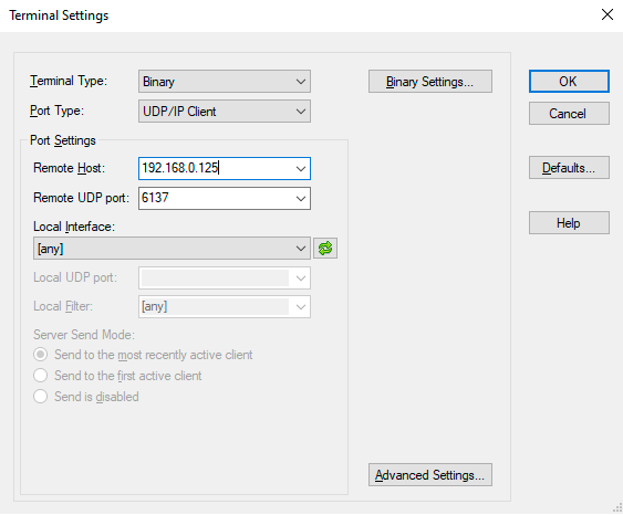
Terminal Application
The UDP protocol commands can be applied to the extenders using a terminal application. You need to install one of them on your control device, for example YAT. #terminal #kvm #usbkvm #icron
Establishing Connection
Follow the steps to establish connection to the AU2K series device:
Step 1.Connect the device to a LAN over Ethernet.
Step 2.Open the terminal application (e.g. YAT).
Step 3.Go to Terminal > Settings.
Step 4.Select the Binary terminal type.
Step 5.Select the UDP/IP Client port type.
Step 6.Add the IP address of the device and the Remote UDP port number (6137).
Step 7.In View > Radix, choose Hexadecimal.
Step 8.Open the connection.
Once the terminal window is opened, you can enter the UDP protocol commands, which are listed in the following sections:
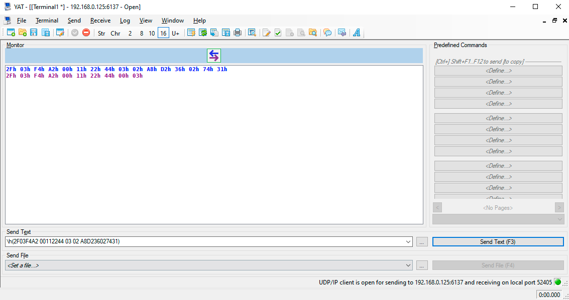
The format of a hexadecimal command in YAT is the following: \h(<UDP_command>)
12.2. Setup
Before you begin configuration, please make sure of the following:
Step 1.Take note of the MAC address of your devices. You can find this information in the lower left corner of the top of the extenders.
Step 2.Connect the extenders to each other (point-to-point mode) or the switch (point-multipoint mode).
Step 3.Connect your host-side transmitter to the host computer via a USB-C cable.
Step 4.Check that your host (or control) computer is in the same network as your extenders.
Step 5.Power on your devices.
Step 6.Pair the extenders with the Pairing to a Device message.
12.3. Protocol Description
The SwitchableUSB: Device Configuration Network Protocol described in this chapter works on top of User Datagram Protocol (UDP). The protocol is created to be able to discover and configure AU2K series devices on a local Ethernet network. The messages can be sent to the device as UDP packages via port no. 6137. In the following examples the packages are sent in Hexadecimal format.
Generic Packet Structure
|
Format |
Explanation |
|
Magic Number |
A value (0x2F03F4A2) that ensures that the following data is a configuration message. |
|
Message ID |
When the client sends a request, it chooses any value to insert in this field. The extender responding to the request will set this field in the reply to the same value. |
|
Protocol Version |
An integer from 0-255. All devices will support protocol 0 and one other protocol version. The Replying Device Information message will inform the client which version of the protocol it must speak in order to communicate with the extender. |
|
Command |
An integer from 0-255. This is the identifier of the command. The combination of the protocol version and the command identify a unique message type. |
▪All multi-byte fields are packed as big endian.
▪Messages are at least 10 bytes and at most 136 bytes in length.
▪Any string fields should be encoded using UTF-8.
Example
»2F03F4A2 00112244 00 00
12.3.1. Legend for the Commands
|
Format |
Description |
|
» |
Sent request |
|
« |
Received response |
INFO:Spaces seen in the examples are for enhancing readability, they can be left out of the commands.
12.4. Network Broadcast
12.4.1. Subnet Broadcast
To broadcast a packet to subnet you only have to use the broadcast IP of the subnet. For example to broadcast to a network configured as an IP range of 192.168.5.xxx, and a netmask of 255.255.255.0, the IP 192.168.5.255 is the broadcast IP address. In case of a network configured as an IP range of 10.xxx.xxx.xxx, and a netmask of 255.0.0.0, the IP 10.255.255.255 is the broadcast IP address.
Since routers drop broadcast IP packets with a destination outside of the network of the source, these broadcast packages must originate in the same network as the target devices.
12.4.2. All Local Subnet Broadcast
By broadcasting to the IP address 255.255.255.255 a broadcast packet can be sent out without knowing previously what the local network is. Microsoft Windows will, however, only send the packet out through the first configured network interface, so on a computer with multiple interfaces, each interface should send a separate broadcast network packet.
12.4.3. Mismatched Network Configuration
When broadcasting to a subnet using the network broadcast address (e.g. 192.168.5.255) and the extender is configured for a different network (e.g. IP=10.0.9.23 and netmask=255.0.0.0), the extender will not respond to the broadcast, as it will not recognize the IP address as a valid broadcast.
This should not happen when a proper DHCP server allocates addresses from the same pool for the network, however, it may happen when assigning static IP addresses or moving units between networks. In case of this occurence, the extender must be reset to a DHCP address in the way seen in the section Using DHCP. After this a static IP address can be assigned to the unit again.
12.5. Generic Replies
12.5.1. Acknowledge
This message is a generic ACK message that will be sent in response to all requests made by clients that do not require returning an additional data payload in the response. The Message ID field should be sufficient to determine which message is being acknowledged.
|
Byte Offset |
||
|
0 |
Magic Number |
|
|
2 |
||
|
4 |
Message ID |
|
|
6 |
||
|
8 |
Protocol Version = 0 |
Command = 3 |
Example
«2F03F4A2 00112244 00 03
12.5.2. Negative Acknowledge
This message is a generic NAK message that may be sent in response to a Pairing to a Device, Removing Device Pairing or Requesting Device Topology message. It indicates to the client that their request was received, but that no action will be taken as a result of that message. The Message ID field should be sufficient to determine which message this is a response to.
|
Byte Offset |
||
|
0 |
Magic Number |
|
|
2 |
||
|
4 |
Message ID |
|
|
6 |
||
|
8 |
Protocol Version = 3 |
Command = 8 |
Example
«2F03F4A2 00112244 03 08
12.6. Supported Messages
12.6.1. Requesting and Replying Device Information
Request
This message is sent from the client to an extender in order to evoke a Replying Device Information message. This message can be sent in a broadcast UDP message in order to discover all of the configurable USB extenders on the local network.
|
Byte Offset |
||
|
0 |
Magic Number |
|
|
2 |
||
|
4 |
Message ID |
|
|
6 |
||
|
8 |
Protocol Version = 0 |
Command = 0 |
Reply
This message is sent from an extender to a client in response to a Requesting Device Information message.
|
Byte Offset |
||
|
0 |
Magic Number |
|
|
2 |
||
|
4 |
Message ID |
|
|
6 |
||
|
8 |
Protocol Version = 0 |
Command = 1 |
|
10 |
MAC Address |
|
|
12 |
||
|
14 |
||
|
16 |
IP Address |
|
|
18 |
||
|
20 |
Network Aquisition Mode |
Supported Protocol Version |
|
22 |
Vendor |
|
|
52 |
||
|
54 |
Product |
|
|
84 |
||
|
86 |
Revision |
|
|
96 |
||
Field Descriptions
|
Field Data Type |
Explanation |
Values |
Value description |
|
MAC address |
The MAC address of the device |
||
|
IP address |
The current IP address of the device |
||
|
Network Acquisition Mode |
0 |
DHCP |
|
|
Supported Protocol Version |
This number specifies what protocol version the device supports beside protocol 0. |
||
|
Vendor |
A 32-byte, NUL-terminated string containing the vendor name of the device. |
||
|
Product |
A 32-byte, NUL-terminated string containing the product name of the device. |
||
|
Revision |
A 12-byte, NUL-terminated string containing the revision number of the device. |
Example
»2F03F4A2 00112244 00 00
«2F03F4A2 00112244 00 01 A8D236027431 C0A8007D 00 03
4C69676874776172652056697375616C20456E67696E656572696E6700000000
55534232302D314742452D485331300000000000000000000000000000000000 322E302E3600000000000000
12.6.2. Ping
This message is sent from a client to the device to check if a device is active. An Acknowledge message will be sent by the device in response.
Request
|
Byte Offset |
||
|
0 |
Magic Number |
|
|
2 |
||
|
4 |
Message ID |
|
|
6 |
||
|
8 |
Protocol Version = 0 |
Command = 2 |
Example
»2F03F4A2 00112244 00 02
«2F03F4A2 00112244 00 03
12.6.3. Requesting and Replying Extended Device Information
Request
Sent by a client to an extender in order to obtain additional information about the device that is not included in the Replying Device Information message from protocol 0.
|
Byte Offset |
||
|
0 |
Magic Number |
|
|
2 |
||
|
4 |
Message ID |
|
|
6 |
||
|
8 |
Protocol Version = 3 |
Command = 0 |
Reply
Sent by an extender to a client in response to a Requesting Extended Device Information message.
|
Byte Offset |
||
|
0 |
Magic Number |
|
|
2 |
||
|
4 |
Message ID |
|
|
6 |
||
|
8 |
Protocol Version = 3 |
Command = 1 |
|
10 |
LEX/REX |
Paired with MAC address |
|
12 |
||
|
14 |
||
|
16 |
||
Last six bytes can be repeated 0 or 1 times for an extender in point-to-point mode, or 0 to 7 times for a host side extender with virtual hub enabled.
Field Descriptions
|
Field Data Type |
Explanation |
Values |
Value description |
|
LEX/REX |
This determines whether the responding device is a host-side extender (LEX), or a device-side extender (REX). |
0 |
Host-side extender |
|
Paired with MAC address |
MAC address of an extender that this device is paired with. This field is optional and may be repeated up to 7 times. |
Example
»2F03F4A2 00112244 03 00
«2F03F4A2 00112244 03 01 00 A8D23602B357001B1302E3A4
This message is sent by a client to instruct an extender to try to pair with a different extender specified in the message. The client must send this message to both the host-side and device-side extenders, the contents adjusted respectively, but the order of the two messages does not matter. The extender will respond with an Acknowledge message if it is able to pair with a new device or a Negative Acknowledge message otherwise.These replies only mean that an attempt will be made to establish a link between the extenders, not that a link is already established. #pairing
In case of pairing several device-side extenders to a host-side extender, this step must be repeated for each pairing. #pairing
Field Descriptions
|
Field Data Type |
Explanation |
Values |
Value description |
|
Pairing to device MAC address |
The MAC address that the client is telling the extender to attempt to pair with. |
Request
|
Byte Offset |
||
|
0 |
Magic Number |
|
|
2 |
||
|
4 |
Message ID |
|
|
6 |
||
|
8 |
Protocol Version = 3 |
Command = 2 |
|
10 |
Pairing to Device MAC Address |
|
|
12 |
||
|
14 |
||
Example
»2F03F4A2 00112244 03 02 A8D236027431
«2F03F4A2 00112244 00 03
»2F03F4A2 00112244 03 02 A8D23602B357
«2F03F4A2 00112244 00 03
12.6.5. Removing Device Pairing
Sent by a client to an extender, instructing it to discard any existing pairing it has. This will effectively disconnect any USB devices that were downstream of the remote extender. The client must send this message to each of the extenders in the pairing. The extenders will respond with an Acknowledge message or with a Negative Acknowledge if it is already unpaired or paired to a different extender.
Field Descriptions
|
Field Data Type |
Explanation |
Values |
Value description |
|
Paired MAC address |
The MAC address that the client is telling the extender to disassociate from. |
Request
|
Byte Offset |
||
|
0 |
Magic Number |
|
|
2 |
||
|
4 |
Message ID |
|
|
6 |
||
|
8 |
Protocol Version = 3 |
Command = 3 |
|
10 |
Paired MAC Address |
|
|
12 |
||
|
14 |
||
Example
»2F03F4A2 00112244 03 03 A8D236027431
«2F03F4A2 00112244 00 03
»2F03F4A2 00112244 03 03 A8D23602B357
«2F03F4A2 00112244 00 03
12.6.6. Requesting and Replying Device Topology
Request
Sent by a client to a host-side extender in order to obtain the set of USB devices in the system. A device-side extender will respond with a Negative Acknowledge to this message.
|
Byte Offset |
||
|
0 |
Magic Number |
|
|
2 |
||
|
4 |
Message ID |
|
|
6 |
||
|
8 |
Protocol Version = 3 |
Command = 4 |
Reply
A host-side extender will send this message in response to a Requesting Device Topology message. The length of this message varies depending on the number of devices in the system. The combination of the information is enough for a client to build and display a device tree.
|
Byte Offset |
||
|
0 |
Magic Number |
|
|
2 |
||
|
4 |
Message ID |
|
|
6 |
||
|
8 |
Protocol Version = 3 |
Command = 5 |
|
10 |
USB Address |
USB Address Of Parent |
|
12 |
Port on Parent |
Is Device a Hub |
|
14 |
USB Vendor ID |
|
|
16 |
USB Product ID |
|
Bytes 10 to 16 can be repeated 0 to 32 times according to the number of USB devices.
INFO:Maximum number of USB devices is 32.
Field Descriptions
|
Field Data Type |
Explanation |
Values |
Value description |
|
USB Address |
An integer from 0 to 127. |
||
|
USB Address of Parent |
An integer from 1 to 127. If a USB Address is seen that is not listed as the USB Address of Parent for any of the devices, then that device is the root of the device topology. |
||
|
Port on Parent |
An integer from 1 to 127. 0 is not a valid number for a port on a hub, so this field will only be 0 if there is no USB device upstream before the host. |
||
|
Is Device a Hub |
0 |
False |
|
|
USB Vendor ID |
The USB Vendor ID from the device descriptor. |
||
|
USB Product ID |
The USB Product ID from the device descriptor. |
Example
»2F03F4A2 00112244 03 04
«2F03F4A2 00112244 03 05 2A27020004580186 2724010104B46506 24000001089D0001
Sent by a client to an extender to tell it to use DHCP to obtain an IP address. This message may be sent either as a UDP broadcast packet or a packet directed to a specific IP address known already. Regardless of whether the message was sent as a broadcast or not, the device will only switch to DHCP mode if the Target MAC Address field matches its own MAC address. When a valid Using DHCP message is received, the extender will send an Acknowledge message before discarding its static address configuration and aquiring an IP address via DHCP. If the Using DHCP message is sent to a device already in DHCP mode, it will still send an Acknowledge response, but no further actions are taken such as IP renewal. The client is able to tell the mode an extender is in by inspecting the Network Aquisition Mode field of the Replying Device Information message. #dhcp
Request
|
Byte Offset |
||
|
0 |
Magic Number |
|
|
2 |
||
|
4 |
Message ID |
|
|
6 |
||
|
8 |
Protocol Version = 3 |
Command = 6 |
|
10 |
Target MAC Address |
|
|
12 |
||
|
14 |
||
Field Descriptions
|
Field Data Type |
Explanation |
|
Target MAC address |
The MAC address of the device that will be set to use DHCP to obtain an IP address. |
Example
»2F03F4A2 00112244 03 06 A8D236027431
«2F03F4A2 00112244 00 03
12.6.8. Using Static IP
Sent by a client to an extender to tell it to use the static network configuration contained in this message. The IP, subnet mask and default gateway, as well as the network configuration are stored in permanent storage, so the device will keep the same network configuration after being power cycled. Similarly to the Using DHCP message, this message can be broadcast or sent to a specific device. Given that the Target MAC Address field matches the MAC address of the device, it will always respond with an Acknowledge message. Sending a Using Static IP message to a device already in a static configuration will enable the client to change the IP, subnet mask or default gateway of the device.
Request
|
Byte Offset |
||
|
0 |
Magic Number |
|
|
2 |
||
|
4 |
Message ID |
|
|
6 |
||
|
8 |
Protocol Version = 3 |
Command = 7 |
|
10 |
Target MAC Address |
|
|
12 |
||
|
14 |
||
|
16 |
IPv4 Address |
|
|
18 |
||
|
20 |
Subnet Mask |
|
|
22 |
||
|
24 |
Default Gateway |
|
|
26 |
||
Field Descriptions
|
Field Data Type |
Explanation |
|
Target MAC Address |
The MAC address of the device that will be set to use static network configuration. |
|
IPv4 Address |
The IPv4 address being assigned to this device encoded as a 32-bit integer. |
|
Subnet Mask |
The subnet mask of the network the device is on. |
|
Default Gateway |
Sets the default gateway of the device. |
Example
»2F03F4A2 00112244 03 07 001B1302E3A4 C0A8007E FFFFFF00 C0A80001
«2F03F4A2 00112244 00 03
12.6.9. Using Filtering Strategy
Sent by a client to an extender to set it to use a certain type of filtering strategy contained in the message. The filtering strategy denotes the type of devices to be filtered out by the extenders. An Acknowledge message will be sent back to the client if the extender supports device class filtering and a valid strategy was selected. Otherwise, a Negative Acknowledge will be sent to the client.
Field Descriptions
|
Field Data Type |
Values |
Value description |
|
Filtering Strategy |
0 |
Allow all devices |
Request
|
Byte Offset |
||
|
0 |
Magic Number |
|
|
2 |
||
|
4 |
Message ID |
|
|
6 |
||
|
8 |
Protocol Version = 3 |
Command = 9 |
|
10 |
Filtering Strategy |
|
Example
»2F03F4A2 00112244 03 09 02
«2F03F4A2 00112244 00 03
12.6.10. Reseting Device
This message is sent from the client to the extender. Upon receiving this message, the device resets.
Request
|
Byte Offset |
||
|
0 |
Magic Number |
|
|
2 |
||
|
4 |
Message ID |
|
|
6 |
||
|
8 |
Protocol Version = 3 |
Command = 12 |
Example
»2F03F4A2 00112244 03 0C
«2F03F4A2 00112244 00 03
12.6.11. Requesting and Replying Configuration Response Data
Request
This message is sent from the client to an extender in order to evoke a Replying Configuration Response Data message.
|
Byte Offset |
||
|
0 |
Magic Number |
|
|
2 |
||
|
4 |
Message ID |
|
|
6 |
||
|
8 |
Protocol Version = 3 |
Command = 13 |
Reply
This message is sent from an extender to a client in response to a Requesting Configuration Response Data message.
|
Byte Offset |
||
|
0 |
Magic Number |
|
|
2 |
||
|
4 |
Message ID |
|
|
6 |
||
|
8 |
Protocol Version = 3 |
Command = 14 |
|
10 |
High Speed Status |
MSA Status |
|
12 |
Vhub Status |
Current Filter Status |
|
14 |
IP Acquisition Mode |
Reserved |
|
16 |
MAC Address |
|
|
18 |
||
|
20 |
||
|
22 |
Reserved |
|
|
24 |
Paired with MAC Address |
|
|
64 |
||
|
66 |
Port Number |
|
|
68 |
IP Address |
|
|
70 |
||
|
72 |
Subnet Mask |
|
|
74 |
||
|
76 |
Default Gateway |
|
|
78 |
||
|
80 |
DHCP Server |
|
|
82 |
||
|
84 |
Number of Vhub Ports |
Reserved |
|
86 |
VID |
|
|
88 |
PID |
|
|
90 |
Brand ID |
|
|
92 |
Vendor |
|
|
120 |
||
|
122 |
Product |
|
|
152 |
||
|
154 |
Revision |
|
|
166 |
||
Field Descriptions
|
Field Data Type |
Explanation |
Values |
Value description |
|
High Speed |
0 |
Disabled |
|
|
MSA |
0 |
Disabled |
|
|
Vhub |
0 |
Disabled |
|
|
Current Filter Status |
0 |
Allow all devices |
|
|
IP Acquision Mode |
0 |
DHCP |
|
|
Reserved |
This field is reserved and is set to 0. |
||
|
MAC Address |
The MAC address of the device. |
||
|
Paired with MAC Address |
MAC address of an extender that this device is paired with. This field is optional and may be repeated up to 7 times. |
||
|
Port Number |
The port number that this device is connected to. |
||
|
IP Address |
The current IP address of the device. |
||
|
Subnet Mask |
The subnet mask of the device. |
||
|
Default Gateway |
The default gateway for the device. |
||
|
DHCP Server |
The DHCP server of the device. |
||
|
Num of Vhub ports |
The number of downstream ports of the device. |
||
|
VID |
The Vendor ID of the device. |
||
|
PID |
The Product ID of the device. |
||
|
Brand ID |
The Brand ID of the device. |
0 |
Non-vendor locked device |
|
Vendor |
A 32-byte NUL-terminated string containing the vendor name of the device. |
||
|
Product |
A 32-byte NUL-terminated string containing the product name of the device. |
||
|
Revision |
A 12-byte NUL-terminated string containing the revision number of the device. |
Example
»2F03F4A2 00112244 03 0D
«2F03F4A2 00112244 03 0E 01 00 01 00 00 00 A8D23602B357 00 00
A8D236027431000000000000000000000000000000000000000000000000000000000000000000000000 17F9 C0A8007F FFFFFF00 C0A80001 C0A80001 07 00 6F27 6E01 0000
4C69676874776172652056697375616C20456E67696E656572696E6700000000
55534232302D314742452D445334000000000000000000000000000000000000 322E302E3600000055534220
12.6.12. Requesting and Replying Link Status
Request
This message is sent from the client to an extender in order to obtain the link status of the paired units.
|
Byte Offset |
||
|
0 |
Magic Number |
|
|
2 |
||
|
4 |
Message ID |
|
|
6 |
||
|
8 |
Protocol Version = 3 |
Command = 15 |
Reply
This message is sent from the extender to the client in response to a Requesting Link Status Information message. The message will contain information for all 7 devices that could be paired. If the number of paired devices is less than 7, the unpaired fields are set to 0. Thus, the size of the structure sent remains the same regardless of the number of paired units.
|
Byte Offset |
||
|
0 |
Magic Number |
|
|
2 |
||
|
4 |
Message ID |
|
|
6 |
||
|
8 |
Protocol Version = 3 |
Command = 16 |
|
10 |
Link Status of Device 1 |
Link Status of Device 2 |
|
12 |
Link Status of Device 3 |
Link Status of Device 4 |
|
14 |
Link Status of Device 5 |
Link Status of Device 6 |
|
16 |
Link Status of Device 7 |
Reserved |
|
18 |
MAC Address of Device 1 |
|
|
20 |
||
|
22 |
||
|
24 |
MAC Address of Device 2 |
|
|
26 |
||
|
28 |
||
|
30 |
MAC Address of Device 3 |
|
|
32 |
||
|
34 |
||
|
36 |
MAC Address of Device 4 |
|
|
38 |
||
|
40 |
||
|
42 |
MAC Address of Device 5 |
|
|
44 |
||
|
46 |
||
|
48 |
MAC Address of Device 6 |
|
|
50 |
||
|
52 |
||
|
54 |
MAC Address of Device 7 |
|
|
56 |
||
|
58 |
||
Field Descriptions
|
Field Data Type |
Explanation |
Values |
Value description |
|
Link Status |
0 |
Device not paired |
|
|
Reserved |
This field is reserved and is set to 0. |
||
|
Paired with MAC Address |
Each MAC address uses 6 bytes and the field value will be set to 0 if there is no device paired. |
Example
»2F03F4A2 00112244 03 0F
«2F03F4A2 00112244 03 10 02 01 00 00 00 00 00 00 A8D23602B357001B1302E3A4000000000000000000000000000000000000000000000000000000000000
12.6.13. Removing All Pairings
This command is sent by the client to an extender to instruct it to clear all of its pairings. This message may be sent to an extender that has no current pairings, but it will have no effect.
Request
|
Byte Offset |
||
|
0 |
Magic Number |
|
|
2 |
||
|
4 |
Message ID |
|
|
6 |
||
|
8 |
Protocol Version = 3 |
Command = 17 |
Example
»2F03F4A2 00112244 03 11
«2F03F4A2 00112244 00 03
12.6.14. Force Pairing to Device
This command is sent by the client to an extender to instruct it to clear all of its existing pairings and then try to pair with a different extender specified in the message. The client must send this message to both a host-side extender and a device-side extender to instruct them to be paired together, but the order of the two messages does not matter. The extender will respond with an Acknowledge message if it is able to pair with a new device or a Negative Acknowledge otherwise. #pairing
INFO:The Acknowledge message only indicates an attempt will be made to establish a link between the extenders, not that a link is already established. #pairing
Field Descriptions
|
Field Data Type |
Explanation |
|
Force Pair to Device MAC Address |
The MAC address that the client is telling the extender to attempt to pair with. |
Request
|
Byte Offset |
||
|
0 |
Magic Number |
|
|
2 |
||
|
4 |
Message ID |
|
|
6 |
||
|
8 |
Protocol Version = 3 |
Command = 18 |
|
10 |
Force Pair to Device MAC Address |
|
|
12 |
||
|
14 |
||
Example
»2F03F4A2 00112244 03 12 A8D23602B357
«2F03F4A2 00112244 00 03
»2F03F4A2 00112244 03 12 A8D236027431
«2F03F4A2 00112244 00 03
12.6.15. Reseting Force Pairing to Device
This command is the same as the Force Pairing to Device command, but it resets the system after the pairing with the other extender happens.
INFO:This command only works when sent to a host-side extender. When sent to a device-side extender, it will reset the device, but pairing will not happen.
Field Descriptions
|
Field Data Type |
Explanation |
|
Force Pair to Device MAC Address |
The MAC address that the client is telling the extender to attempt to pair with. |
Request
|
Byte Offset |
||
|
0 |
Magic Number |
|
|
2 |
||
|
4 |
Message ID |
|
|
6 |
||
|
8 |
Protocol Version = 3 |
Command = 19 |
|
10 |
Force Pair to Device MAC Address |
|
|
12 |
||
|
14 |
||
Example
»2F03F4A2 00112244 03 13 A8D23602B357
«2F03F4A2 00112244 00 03
12.6.16. Writing the Extended Configuration Variable
This command writes the extended configuration variable. It is used to control the following configuration parameters:
▪Simultaneous Users Interaction (SUI) and Mass Storage Acceleration (MSA)
▪Enabling/Disabling DHCP option
▪DCF configuration
The client will set the bit of configuration mask corresponding to which configuration variable they want to change and set the configuration variable as defined below in the field descriptions. The system will reset after a variable is set.
ATTENTION!Please be aware that while this command is packed as big endian, depending on the terminal application and the Operation System, it may be reversed by the application to display as little endian.
Field Descriptions
|
Field Data Type |
Explanation |
Values |
Value description |
|
Configuration Mask |
This is a 16-bit mask, in which only the first 4 are used. The remaining are reserved and set to 0. |
Bit 0 |
Change only SUI and MSA fields in the configuration variable. |
|
Configuration Variable |
This is the 32 bits defined as it follows: |
||
|
Simultaneous Users Interaction (SUI) and Mass Storage Acceleration (MSA) (2-bit field starting at bit 0) |
0 |
SUI off, MSA off |
|
|
Enabling/Disabling the DHCP option 60 (1-bit field, at bit 2) |
|||
|
Reserved, set to 0 (1-bit field, at bit 3) |
|||
|
Disabling DCF or Set DCF options - DCF configuration field (4-bit field, starting at bit 4) |
0 |
Allow all devices (DCF disabled) |
Request
|
Byte Offset |
||
|
0 |
Magic Number |
|
|
2 |
||
|
4 |
Message ID |
|
|
6 |
||
|
8 |
Protocol Version = 3 |
Command = 50 |
|
10 |
Configuration Mask |
|
|
12 |
Extended Configuration Variable |
|
|
14 |
||
Example
»2F03F4A2 00112244 03 32 0100 01000000
«2F03F4A2 00112244 00 03
INFO:Please take note that depending on the SUI setting, the extender may take up several USB tiers. If SUI is turned off, the extender takes up one USB tier. If SUI is turned on, it takes up two USB tiers. For optimal operation please make sure you do not exceed the maximum tier level (generally 7).
12.6.17. Requesting the Extended Configuration Variable
Request
This command is sent from the client to the extender to request the extended configuration variable.
|
Byte Offset |
||
|
0 |
Magic Number |
|
|
2 |
||
|
4 |
Message ID |
|
|
6 |
||
|
8 |
Protocol Version = 3 |
Command = 51 |
Reply
This command is a response to the Requesting Extended Configuration Variable command, sent from the extender to the client. It offers the extended configuration variable.
|
Byte Offset |
||
|
0 |
Magic Number |
|
|
2 |
||
|
4 |
Message ID |
|
|
6 |
||
|
8 |
Protocol Version = 3 |
Command = 52 |
|
10 |
Extended Configuration Variable |
|
|
12 |
||
Field Descriptions
|
Field Data Type |
Explanation |
Values |
Value description |
|
Configuration Variable |
This is the 32 bits defined as it follows: |
||
|
Simultaneous Users Interaction (SUI) and Mass Storage Acceleration (MSA) (2-bit field starting at bit 0) |
0 |
SUI off, MSA off |
|
|
Enabling/Disabling the DHCP option 60 (1-bit field, at bit 2) |
|||
|
Reserved, set to 0 (1-bit field, at bit 3) |
|||
|
Disabling DCF or Set DCF options - DCF configuration field (4-bit field, starting at bit 4) |
0 |
Allow all devices (DCF disabled) |
Example
»2F03F4A2 00112244 03 33
«2F03F4A2 00112244 03 34 00000001
This chapter is meant to help customers perform firmware updates on our products by giving a few tips on how to start and by explaining the features of the Lightware Device Updater v2 (LDU2) software. The latest software and firmware pack can be downloaded from www.lightware.com.
ATTENTION!While the firmware is being updated, the normal operation mode is suspended, as the device is switched to bootload mode. Signal processing is not performed. Do not interrupt the firmware update. If any problem occurs, reboot the device and restart the process.
13.1. Introduction

Lightware Device Updater v2 (LDU2) software is the second generation of the LFP-based (Lightware Firmware Package) firmware update process. #update #firmwareupdate
13.2. Preparation
Most Lightware devices can be controlled over several interfaces (e.g. Ethernet, USB, RS-232). But the firmware can be updated usually over one dedicated interface, which is the Ethernet in most cases.
If you want to update the firmware of one or more devices, you need the following:
▪LFP2 file,
▪LDU2 software installed on your PC or Mac.
Both can be downloaded from www.lightware.com.
Optionally, you can download the release notes file in HTML format.
13.2.1. Reserved Ports of the SDVoE Control Server
If the BlueRiver AV Manager and the SDVoE Control Server is installed once, the following ports are reserved by the software:
|
Protocol |
Port Number |
Description |
|---|---|---|
|
TCP |
5920 |
BlueRiver AV Manager Service |
|
TCP |
5936 |
BlueRiver AV Manager SDVoE API Service |
|
TCP |
20020 |
TCI API |
|
TCP |
5148 |
BlueRiver AV Manager |
ATTENTION!If the following ports are opened, the LDU2 cannot discover the TPN/OPTN series devices. Lightware recommends stopping these services until the firmware updating is completed.
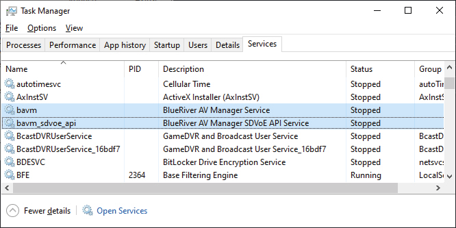
13.2.2. About the Firmware Package (LFP2 File)
All the necessary tools and binary files are packed into the LFP2 package file. You only need this file to do the update on your device.
▪This allows the use of the same LFP2 package for different devices.
▪The package contains all the necessary components, binary, and other files.
▪The release notes is included in the LFP2 file, and is displayed in the window where you select the firmware package file in LDU2.
INFO:The size of the LFP2 file is more than 200 MB due to the components of the package. That is not a fault: the Device runs an embedded Linux inside that is necessary for the complex functions and features of the device.
13.2.3. LDU2 Installation
ATTENTION!Minimum system requirement: 2 GB RAM. The minimum display resolution is 1600x900.
INFO:The Windows and the Mac applications have the same look and functionality.

Download the software from www.lightware.com/en/products/Software/lightware-device-updater-2.
Installation in case of Windows OS
Run the installer. If the User Account Control displays a pop-up message, click Yes.
Installation Modes
|
Normal install |
Snapshot install |
|
Available for Windows, MacOS and Linux |
Available for Windows |
|
The installer can update only this instance |
Cannot be updated |
|
One updateable instance may exist for all users |
Many different versions can be installed for all users |
ATTENTION!Using the default Normal install is highly recommended.
INFO:If you have a previously installed version, you will be prompted to remove the old version before installing the new one.
Installation in case of macOS

Mount the DMG file by double clicking on it, and drag the LDU2 icon over the Applications icon to copy the program into the Applications folder. If you want to copy LDU2 into another location, just drag the icon over the desired folder.
ATTENTION!Please check the firewall settings on the macOS device. LDC needs to be added to the exeptions of the blocked softwares for the proper operation.
INFO:This type of installer is equal with the Normal install of Windows.
Installation in case of Linux

Step 1.Download the archive file (tar.gz) from www.lightware.com and unpack it to a temp folder.
Step 2.Run the install_ldu2.sh file in the temp folder. The script will install LDU2 into the following folder: HOME/.local/share/lightware/ldu2.
Step 3.The folder above will contain this file: LightwareDeviceUpdaterV2.sh, which can be used to start LDU2.
13.3. Running the Software
You have two options:
▪Starting the LDU2 by double-clicking on the shortcut/program file, or
▪Double-clicking on an LFP2 file.
LDU2 Auto-Update
At startup, the software checks if a newer version is available on the web.
Main Screen

When the software is started by the shortcut, the device discovery screen appears. Press the Discover devices button to start finding the Lightware devices:
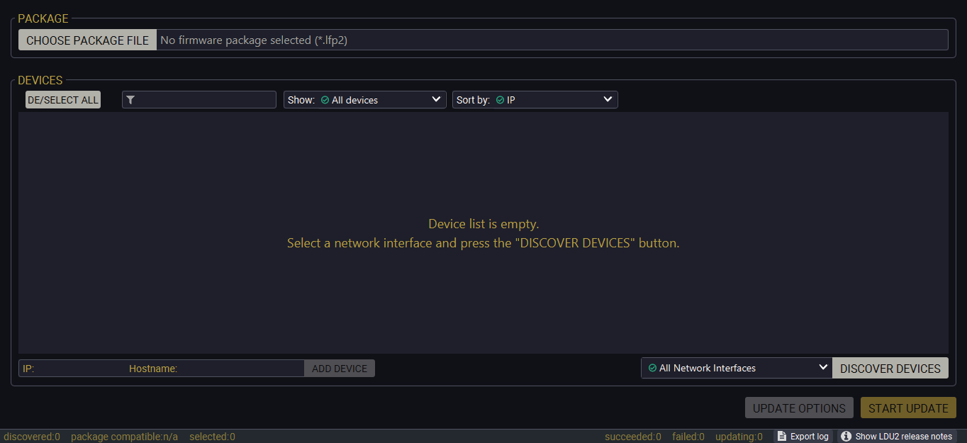
If you start the software by double-clicking on the LFP2 file, the firmware will be loaded. Press the Discover devices button; all the devices will be listed that are compatible with the selected firmware pack.
INFO:If you press the Choose package file button, the release notes of the LFP2 file will be displayed in the right panel; see the Step 1. Select the Firmware Package section.
Device List
When the discovery has completed, the devices available on the network are listed in the application.
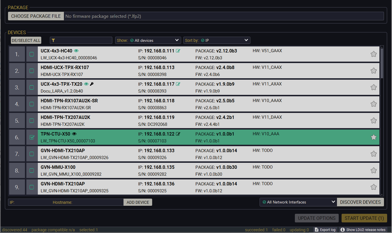
If the desired device is not discovered, you can add it by typing the IP address or the host name in the dedicated field and pressing the Add device button.
ATTENTION!If the device cannot be added by the hostname, please use the IP address.
Legend of the Icons
|
|
IP address editor |
The IP address of the device can be changed in the pop-up window. |
|
|
Identify me |
Clicking on the icon results in the front panel LEDs blinking for 10 seconds, which helps to identify the device phisically. |
|
|
Favorite device |
The device has been marked, thus the IP address is stored. When a device is connected with that IP address, the star will be highlighted in that line. |
|
|
Further information available |
Device is unreachable. Change the IP address by pressing the IP address editor icon or use the front panel buttons (if available). |

|
Service mode |
The device is in bootload mode. Backup and restore cannot be performed in this case. |


ATTENTION!While the firmware is being updated, the normal operation mode is suspended, as the device is switched to bootload mode. Signal processing is not performed. Do not interrupt the firmware update. If any problem occurs, reboot the unit and restart the process.
Keeping the Configuration Settings
By default, device configuration settings are restored when firmware update is finished. If factory reset has been chosen in the parameters window, all device settings will be erased. In the case of factory reset, you can save the settings of the device in the Lightware Device Controller (LDC) software and restore it later.
The following flow steps demonstrate how this function works in the background.
Step 1.Create a backup
The current configuration of the device is being saved into a configuration backup file on your computer.
Step 2.Start the Update
The device reboots and starts in bootload mode (firmware update mode).
Step 3.Upgrade
The CPU firmware is changed to the new one.
Step 4.Factory reset
All configuration settings are restored to the factory default values.
Step 5.Conversion / Restore
The firmware package checks the backup data before the restoration procedure, and if it is necessary, a conversion is applied to avoid incompatibility problems between the firmware versions. All configuration settings are restored to the device after the conversion.
If the factory default option is selected in the Parameters window, the conversion / restore procedure will not be performed!
Step 6.Finish
Once the firmware update procedure is finished, the device reboots and is ready to use.
13.5. Device IP Change in the CTU during Firmware Update
DIFFERENCE:The IP change affects the device updating to v1.5.0 firmware package only.
13.5.1. MAC Address Expansion
In an earlier firmware release in case of the TPN-CTU-X50 model the Management VLAN feature was introduced. However, the devices reported the same MAC address on the Management and Default VLANs, causing issues. In the firmware update versions listed below, all of these devices will receive additional MAC addresses to support network separation and security requirements.
As such, from these firmwares on, a distinct MAC address will be assigned to the Management network. This, however, will result in getting a different IP address from the DHCP server if the device is connected via the Management network.
The new IP address cannot be determined automatically, but the device will appear at a new IP address assigned by the DHCP server after the update.
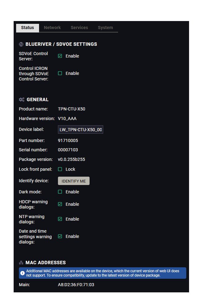
|
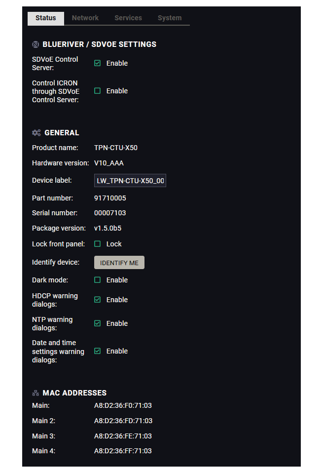
|
|
The MAC address list of the CTU before update |
The MAC address list of the CTU after update |
13.5.2. Issues During Update
If the devices described are updated to the FW version or newer as seen above while connected on the Management network and DHCP active, the IP address will change along the MAC address as described. This change is detected by the LDU2, but the new IP address will not be available automatically, only upon discovery following the reboot.
The Lightware Device Updater V2 (LDU2) version v2.34.0 contains a pop-up window to warn users of this event transpiring.
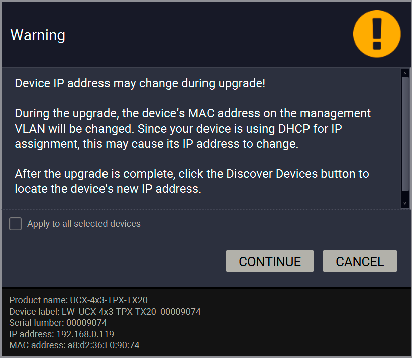
13.6. Updating Via GUI - TPN-CTU-X50 Control Unit
DIFFERENCE:This section relates to the updating of TPN-CTU-X50 control unit only. See the updating steps of the endpoint devices in the Updating Via GUI - TPN/OPTN series Endpoints section.
Step 1. Select the Firmware Package
Click on the Choose Firmware Package button and navigate to the location where the LFP2 file of the CTU is saved. When you click on the name of the package, the preview of the release notes is displayed on the right side.
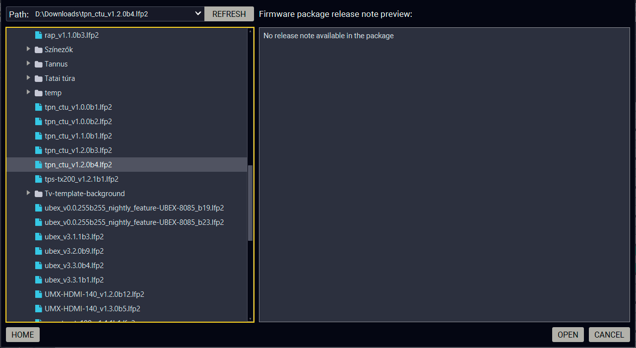
Firmware file browser and the release notes window
After the package file is loaded, the list is filtered to show compatible devices only. The current firmware version of the device is highlighted in orange if it is different from the version of the package loaded.
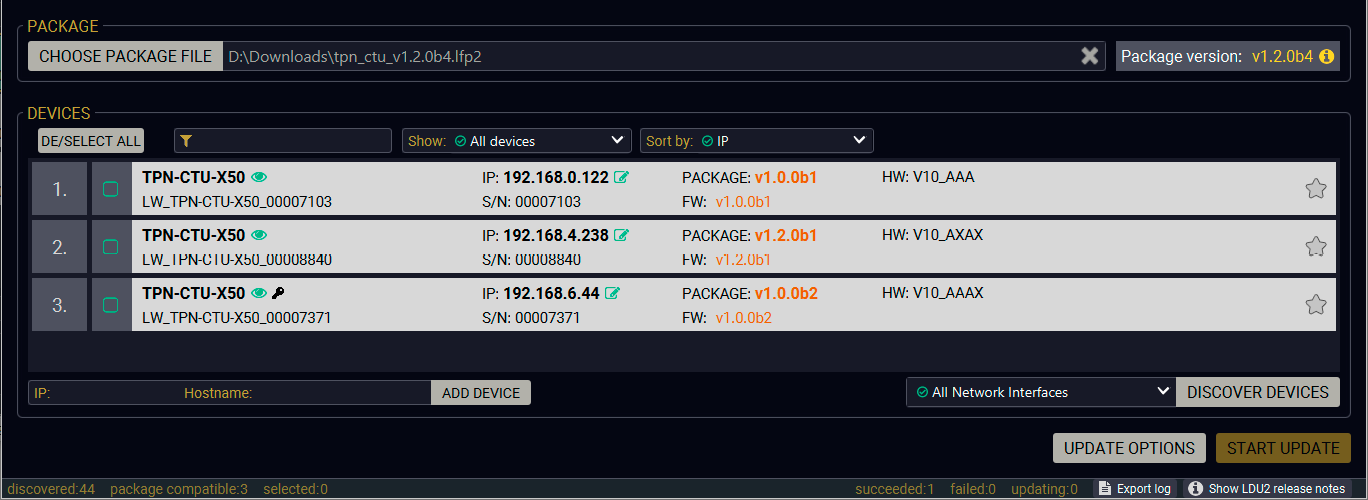
Filtered device list based on the selected firmware package
Step 2. Select the Device for Updating
Pick the device for updating. The selected line will be highlighted in green.
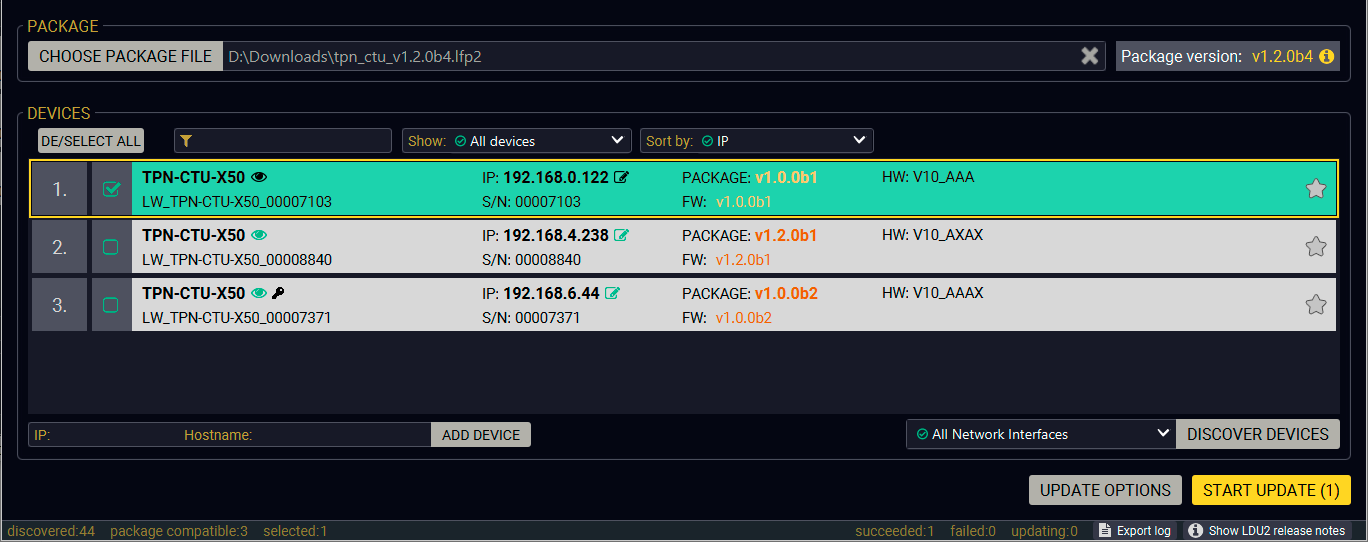
The unit is selected for updating
TIPS AND TRICKS:If you are not sure which device is connected to your controller device directly, use the Identify me feature clicking on the  button. It makes the front panel LED blink in green for 10 seconds. The feature helps to identify the device itself in the rack shelf or on the desk.
Step 3. Check the Update Options.
ATTENTION!The default settings in the Parameters window should be fine for most cases. Please do not modify them if it is not necessary.

Click on the Parameters button to configure the firmware update.
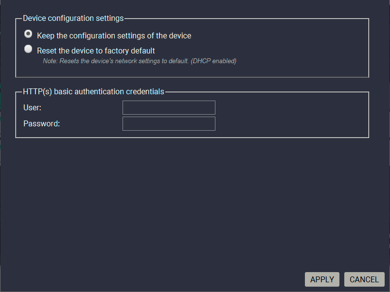
Parameters menu for the CTU
Device Configuration Settings
▪Keep the configuration settings of the device: the configuration settings of the CTU will be restored after the firmware update.
▪Reset the device to factory default: if it is checked, all user settings and parameters will be cleared and the factory default settings will be applied to the device when the update is done. See the whole list of factory default settings of the endpoint device in the Factory Default Settings section.
HTTP(s) Basic Authentication Credentials
Authentication helps limit the access to the device by setting a username (admin) and password. For more details, see the Basic Authentication section. No password is set by default, the authentication can be enabled after setting a password.
The authentication password can be set here for HTTP/HTTPS ports. UTF-8 characters are allowed. Min length: 10 characters, max length: 100 characters. The password string can not be queried. #password
Press the Apply button to finish the Update Options.
Step 4. Start the Update and Wait until It is Finished.
Click on the Start Update button to start the procedure.
The status is shown in percent in the right side of the device line and the status of all of the procedures is shown in the lower light green progress bar.
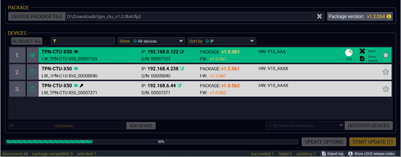
Firmware update is in progress
INFO:The device might reboot several times during the firmware update procedure.
Step 5. Wait until the Unit Reboots with the New Firmware.
Once the firmware update procedure is completed, the unit reboots with the new firmware.
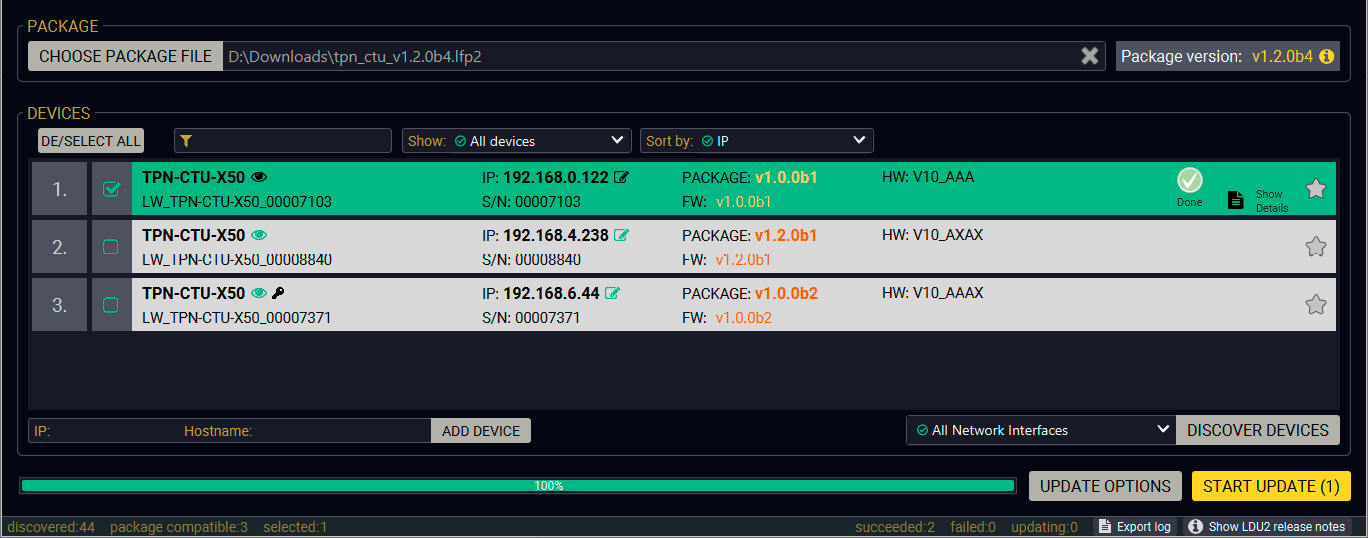
Firmware update procedure is done
13.7. Updating Via GUI - TPN/OPTN series Endpoints
DIFFERENCE:This section related to the updating of TPN/OPTN series endpoint devices only. See the updating steps of the CTU in the Updating Via GUI - TPN-CTU-X50 Control Unit section.
Step 1. Select the Firmware Package
Click on the Choose Firmware Package button and navigate to the location where the LFP2 file of the CTU is saved. When you click on the name of package, the preview of the release notes is displayed on the right side.
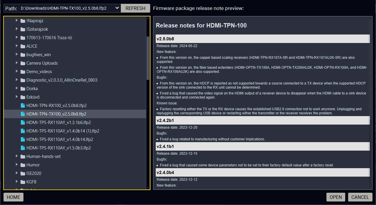
Firmware file browser and the release notes window
After the package file is loaded, the list is filtered to show compatible devices only. The current firmware version of the device is highlighted in orange if it is different from the version of the package loaded.
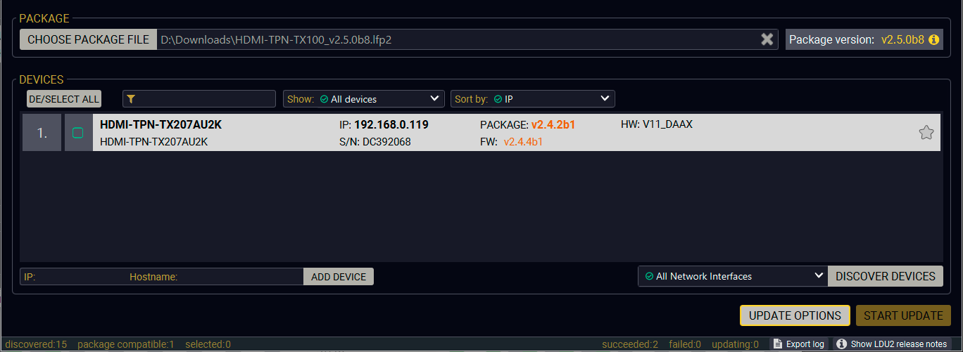
Filtered device list based on the selected firmware package
Step 2. Select the Device for Updating
Pick the device(s) for updating. The selected line will be highlighted in green.
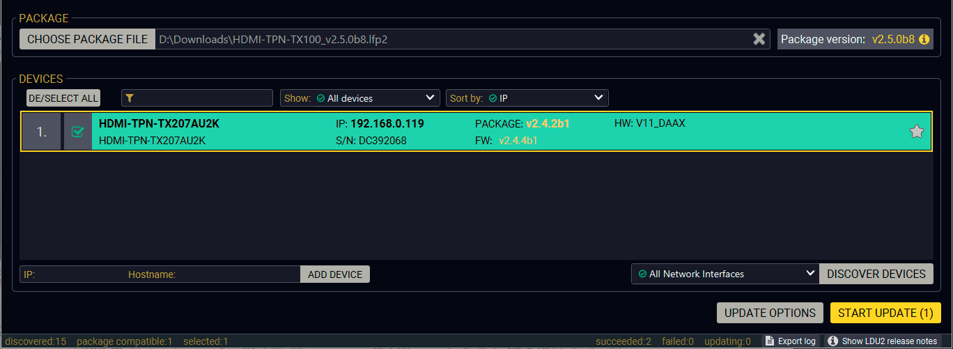
The unit is selected for updating
Step 3. Check the Update Options.
ATTENTION!The default settings in the Parameters window should be fine for most cases. Please do not modify them if it is not necessary.
Click on the Parameters button to configure the firmware update.
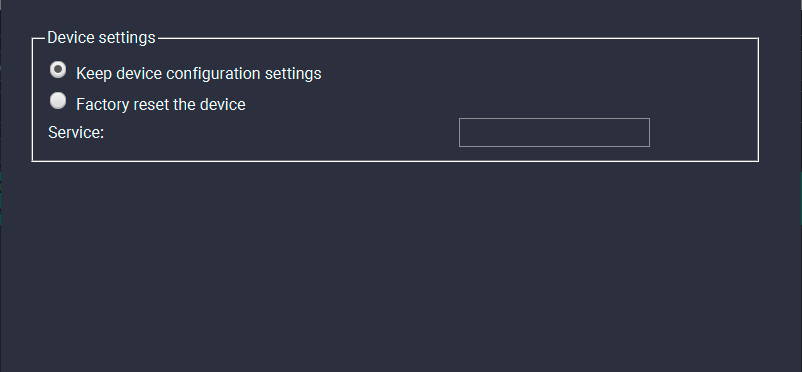
Parameters menu for the endpoint devices
Device Configuration Settings
▪Keep the configuration settings: the configuration settings of the endpoint will be restored after the firmware update.
▪Factory reset the device: if it is checked, all user settings and parameters will be cleared and the factory default settings will be applied to the device when the update is done.
Press the Apply button to finish the Update Options.
Start the Update and Wait until It is Finished.
Click on the Start Update button to start the procedure.
The status is shown in percent in the right side of the device line and the status of all of the procedures is shown in the lower light green progress bar.
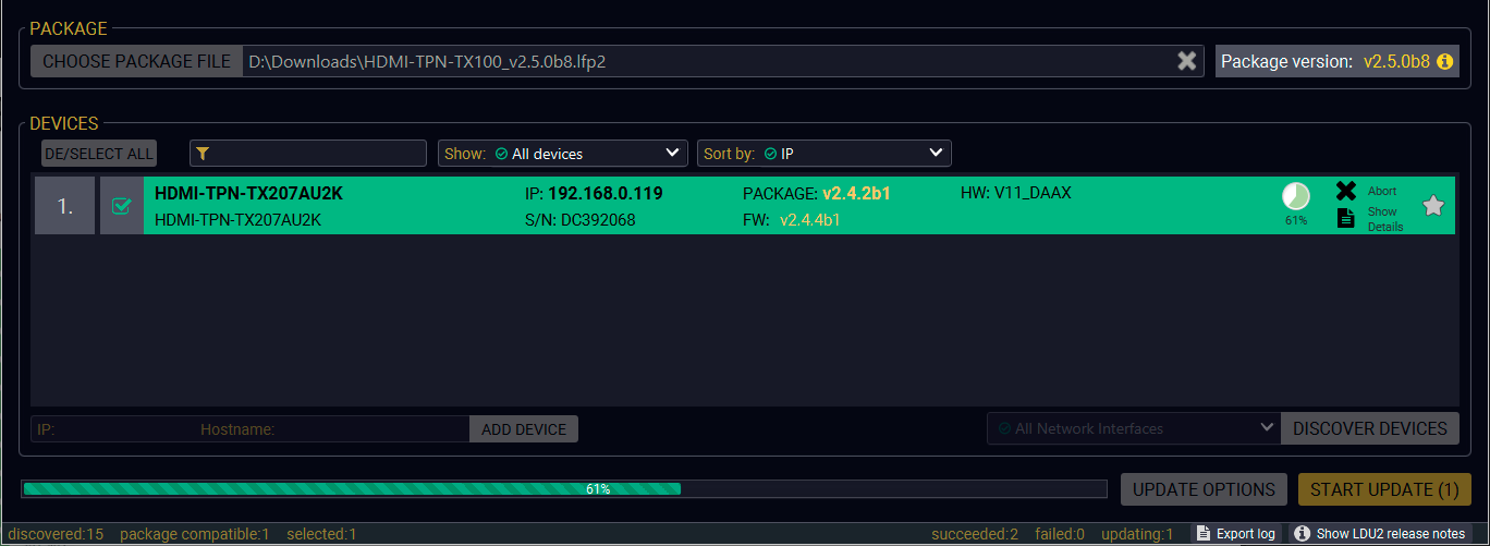
Firmware update is in progress
INFO:The device might reboot several times during the firmware update procedure.
Step 5. Wait until the Unit Reboots with the New Firmware.
Once the firmware update procedure is completed, the unit reboots with the new firmware.
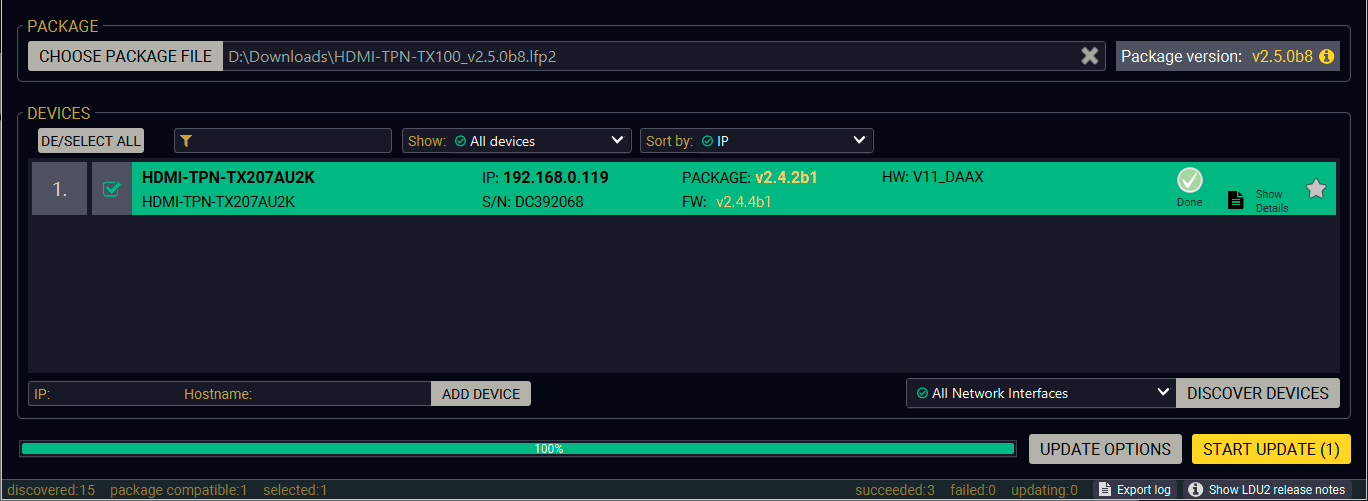
Firmware update procedure is done
13.8. Command Line Interface (CLI)
DIFFERENCE:The Command Line Interface is available from LDU2 v2.9.0b9.
The CLI of the LDU2 software is a simple tool for creating scriptable device updates without the need of human interactions. It allows batch updating just like in case of GUI usage.
13.8.1. How to Run
Running under Windows® OS
The installer of LDU2 puts the following file into the installation folder:
LightwareDeviceUpdaterV2_CLI.cmd
CLI is available via this file, the exe is not suitable for that purpose. Open a command line window to execute or test the features directly.
Step 1.Open an Explorer window where the cmd file is located, the default is:
c:\Program Files (x86)\Lightware\Lightware Device Updater V2\LightwareDeviceUpdaterV2_CLI.cmd.
Step 2.Click on the address line (highlighted in blue in the picture), type cmd.exe and press enter. The command interpreter window of Windows is opened at the path of the LDU2 install folder.
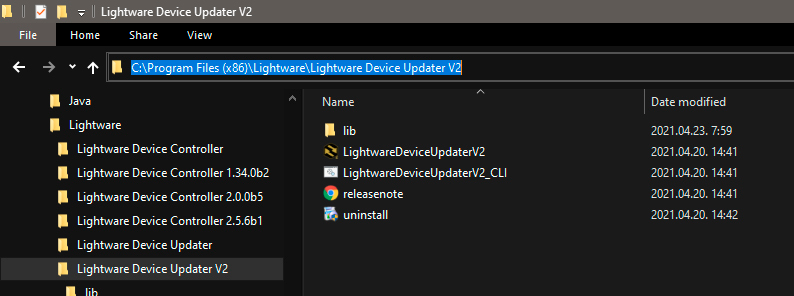
Step 3.Now you can use the LightwareDeviceUpdaterV2_CLI.cmd file with the commands and options, which are described in the coming sections:
Running under Linux
The Command Line Interface under Linux Operating Systems can be run by the following:
LightwareDeviceUpdaterV2.sh.
Running an update:
bash LightwareDeviceUpdaterV2.sh update --ip 172.24.5.27 --package ~/Downloads/taurus_v1.3.3b3.lfp2
The commands and options are the same under Windows® and Linux, too. The following sections contain examples with LightwareDeviceUpdaterV2_CLI.cmd.
13.8.2. How to Use
Command Structure
The commands can be run over CLI in the following way:
LightwareDeviceUpdaterV2_CLI.cmd [command] [options]
[Command]: a certain command described in the coming sections; only one command can be run at a time
[Options]: mandatory and/or optional parameters of the command, if any. Optional parameters have a default value, which can be found at each affected command. You only have to define the parameter if you want to apply a different value. The order of the options is arbitrary.
Important Notes
▪CLI is case-sensitive (including commands, options and other parameters).
▪There is no limit regarding the number of the devices to update. At most 20 devices are updated simoultaneously, when one of them is finished, the following (21st) will be started automatically.
▪If an update is failed, the IP address of the affected device(s) are listed at the end.
13.9. CLI Commands
INFO:The commands and options described in the following sections are the same under Windows® and Linux, too. The examples contain LightwareDeviceUpdaterV2_CLI.cmd.
About the Examples
▪Sent command is in blue, response is in grey.
▪If the response in practice is longer than listed in the example, this symbol can be seen: [...].
13.9.1. Help
The defined commands and options can be listed by the help command.
Command
LightwareDeviceUpdaterV2_CLI.cmd help
Example
C:\Program Files (x86)\Lightware\Lightware Device Updater V2>LightwareDeviceUpdaterV2_CLI.cmd help
C:\Program Files (x86)\Lightware\Lightware Device Updater V2>lib\jre\bin\java.exe -jar lib\ldu2.jar help
Command line usage:
Win: LightwareDeviceUpdaterV2_CLI.cmd [command] [options]
Linux: LightwareDeviceUpdaterV2.sh [command] [options]
Commands:
* help
* version
* update
* deviceInfo
* restore
* packageOptions
[...]
13.9.2. LDU2 Version
The response shows the version of the LDU2 and the version of the Script API (the Application Programming Interface that is used by the LDU2 and the script).
Command
LightwareDeviceUpdaterV2_CLI.cmd version
Example
C:\Program Files (x86)\Lightware\Lightware Device Updater V2>LightwareDeviceUpdaterV2_CLI.cmd version
C:\Program Files (x86)\Lightware\Lightware Device Updater V2>lib\jre\bin\java.exe -jar lib\ldu2.jar version
LDU2 version: 2.10.0b6
Script API version: 1.3.10
13.9.3. Check For New LDU2 Version
The following command can be used to check if an update of LDU2 is available. This is just a request, since the CLI is not suitable for handling the complete installer of the software.
Command
LightwareDeviceUpdaterV2_CLI.cmd checkForUpdates
Example 1
c:\Program Files (x86)\Lightware\Lightware Device Updater V2>LightwareDeviceUpdaterV2_CLI.cmd checkForUpdates
c:\Program Files (x86)\Lightware\Lightware Device Updater V2>lib\jre\bin\java.exe -jar lib\ldu2.jar checkForUpdates
Current LDU2 version: 2.10.0b6
LDU2 is up-to-date
Example 2
c:\Program Files (x86)\Lightware\Lightware Device Updater V2>LightwareDeviceUpdaterV2_CLI.cmd checkForUpdates
c:\Program Files (x86)\Lightware\Lightware Device Updater V2>lib\jre\bin\java.exe -jar lib\ldu2.jar checkForUpdates
Current LDU2 version: 2.9.1b1
New version is available online: 2.10.0b6
Download URL: http://update.lightware.hu/ldu2/lwr/v2.10.0b6/install_LDU2_v2.10.0b6.exe
13.9.4. Device Info
The most important information about the selected device is displayed; see the example for more details.
Command
LightwareDeviceUpdaterV2_CLI.cmd deviceInfo [options]
Options
|
Option |
Description |
Required? |
|
-i or --ip |
List of IP addresses of devices to be updated |
one of them is mandatory |
|
-n or --hostName |
List of host names of devices to be updated |
|
|
-v or --packageVersion |
Shows installed package version only |
optional |
Example 1
C:\Program Files (x86)\Lightware\Lightware Device Updater V2>LightwareDeviceUpdaterV2_CLI.cmd deviceInfo --ip 192.168.0.100
C:\Program Files (x86)\Lightware\Lightware Device Updater V2>lib\jre\bin\java.exe -jar lib\ldu2.jar deviceInfo --ip 192.168.0.100
Product name: MMX2-4x3-H20
IP address: 192.168.1.19
Serial number: 00007316
MAC address: a8:d2:36:F0:73:16
Part number: 91310078
Device label: LW_MMX2-4x3-H20_00007316
Package version: v1.3.3b3
CPU FW version: v1.3.3b3
HW version: V10_KAK1
Operation mode: Application mode
Example 2
C:\Program Files (x86)\Lightware\Lightware Device Updater V2>LightwareDeviceUpdaterV2_CLI.cmd deviceInfo --ip 192.168.1.7 --packageVersion
C:\Program Files (x86)\Lightware\Lightware Device Updater V2>lib\jre\bin\java.exe -jar lib\ldu2.jar deviceInfo --ip 192.168.0.100 --packageVersion
v1.3.3b3
13.9.5. Update
This command can be used to update the firmware of the devices.
Command
LightwareDeviceUpdaterV2_CLI.cmd update [options]
Options
|
Option |
Description |
Required? |
|
-p or --package |
The path of the firmware package file |
yes |
|
-i or --ip |
List of IP addresses of devices to be updated |
one of them is mandatory |
|
-n or --hostName |
List of host names of devices to be updated |
|
|
-r or --reportProgress |
Report update progress in percentage form. Default: false |
optional |
|
Package-specific options |
Certain LFP2 packages have features that can be applied at this command; see the Package Options section. |
optional |
ATTENTION!The configuration is restored automatically if the factory default option is not applied in the update command. In that case, there is no need to run the restore command after the update.
Example
C:\Program Files (x86)\Lightware\Lightware Device Updater V2>LightwareDeviceUpdaterV2_CLI.cmd update --ip 192.168.1.19 --package C:\Firmwares\taurus_v1.3.3b3.lfp2 --reportProgress
C:\Program Files (x86)\Lightware\Lightware Device Updater V2>lib\jre\bin\java.exe -jar lib\ldu2.jar update --ip 192.168.1.19 --package C:\Firmwares\taurus_v1.3.3b3.lfp2 --reportProgress
[2022-02-11 11:22:52.820] [ INFO] [ main] - Device IPs: [192.168.1.19]
[2022-02-11 11:22:58.317] [ INFO] [ main] - All selected devices are available over the network.
[2022-02-11 11:23:01.308] [ INFO] [ main] - All the selected devices are compatible with the specified package.
[2022-02-11 11:23:04.356] [ INFO] [ 192.168.1.19] - Taurus UCX update process started
[2022-02-11 11:23:04.496] [ INFO] [ 192.168.1.19] - Update API version: 1.0
[2022-02-11 11:23:04.525] [ INFO] [ 192.168.1.19] - Update parameters: deviceIp: 192.168.1.19, factoryDefault: false
[2022-02-11 11:23:04.556] [ INFO] [ 192.168.1.19] - Update protocol: http://
[2022-02-11 11:23:04.558] [ INFO] [ 192.168.1.19] - Authentication type: NONE
[2022-02-11 11:23:04.737] [ INFO] [ 192.168.1.19] - Device info: Product name: MMX2-4x3-H20, Device label: LW_MMX2-4x3-H20_00007316, Serial number: 00007316, Mac address: a8:d2:36:F0:73:16, Ip address: 192.168.1.19, Host name: , Package version: v1.3.3b3, Part number: 91310078, Hw version: V10_KAK1
[2022-02-11 11:23:04.753] [ INFO] [ 192.168.1.19] - Uploading firmware package.
[2022-02-11 11:32:54.050] [ INFO] [ProgressReporter] - Progress: 13%
[2022-02-11 11:32:59.056] [ INFO] [ProgressReporter] - Progress: 19%
[2022-02-11 11:33:04.060] [ INFO] [ProgressReporter] - Progress: 25%
[2022-02-11 11:33:09.067] [ INFO] [ProgressReporter] - Progress: 32%
[2022-02-11 11:33:14.079] [ INFO] [ProgressReporter] - Progress: 38%
[2022-02-11 11:33:19.091] [ INFO] [ProgressReporter] - Progress: 40%
[2022-02-11 11:33:24.098] [ INFO] [ProgressReporter] - Progress: 43%
[2022-02-11 11:33:29.112] [ INFO] [ProgressReporter] - Progress: 46%
[2022-02-11 11:33:34.122] [ INFO] [ProgressReporter] - Progress: 49%
[2022-02-11 11:33:39.133] [ INFO] [ProgressReporter] - Progress: 52%
[2022-02-11 11:33:44.135] [ INFO] [ProgressReporter] - Progress: 55%
[2022-02-11 11:33:49.138] [ INFO] [ProgressReporter] - Progress: 58%
[2022-02-11 11:33:54.144] [ INFO] [ProgressReporter] - Progress: 61%
[2022-02-11 11:33:59.154] [ INFO] [ProgressReporter] - Progress: 64%
[2022-02-11 11:34:04.168] [ INFO] [ProgressReporter] - Progress: 67%
[2022-02-11 11:34:09.169] [ INFO] [ProgressReporter] - Progress: 70%
[2022-02-11 11:25:01.556] [ INFO] [ 192.168.1.19] - Package upload finished.
[2022-02-11 11:25:01.611] [ INFO] [ 192.168.1.19] - Starting internal update process. Device is about to reboot.
[2022-02-11 11:25:01.645] [ INFO] [ 192.168.1.19] - Package file has been uploaded successfully.
The device will now update itself, which may take tens of minutes.
LDU2 is now disconnecting from the device. Please wait until the device finishes the update.
[2022-02-11 11:25:01.646] [ INFO] [ 192.168.1.19] - Done
All 1 update(s) finished successfully.
The lines containing "ProgressReporter" can be enabled optionally. If it is enabled, the current state is displayed every 5 seconds.
ATTENTION!As the example shows the firmware update progress is not finished at the "Done" line, but the firmware package is uploaded into the device. The device will run the update progress internally.
Shows package-specific update options.
Command
LightwareDeviceUpdaterV2_CLI.cmd packageOptions [options]
Options
|
Option |
Description |
Required? |
|
-p or --package |
The path of the firmware package file |
yes |
Example
c:\Program Files (x86)\Lightware\Lightware Device Updater V2>LightwareDeviceUpdaterV2_CLI.cmd packageOptions --package f:\!!!LIGHTWARE\firmware\taurus_v1.3.3b3.lfp2
Login options:
--user : HTTP(s) basic authentication user (Default: empty string)
--pw : HTTP(s) basic authentication password (Default: empty string)
A package option example can be seen in the following section.
13.9.7. Complex Example
The following options applied:
▪Firmware is updated
▪Authentication is enabled
C:\Program Files (x86)\Lightware\Lightware Device Updater V2>LightwareDeviceUpdaterV2_CLI.cmd update --ip 192.168.1.19 --package C:\Firmwares\taurus_v1.3.3b3.lfp2 --user admin --pw 12345 --reportProgress
C:\Program Files (x86)\Lightware\Lightware Device Updater V2>lib\jre\bin\java.exe -jar lib\ldu2.jar update --ip 192.168.1.19 --package C:\Firmwares\taurus_v1.3.3b3.lfp2 --user admin --pw 12345 --reportProgress
[2022-02-11 11:32:40.831] [ INFO] [ main] - Device IPs: [192.168.1.19]
[2022-02-11 11:32:46.096] [ INFO] [ main] - All selected devices are available over the network.
[2022-02-11 11:32:49.035] [ INFO] [ main] - All the selected devices are compatible with the specified package.
[2022-02-11 11:32:51.994] [ INFO] [ 192.168.1.19] - Taurus UCX update process started
[2022-02-11 11:32:52.087] [ INFO] [ 192.168.1.19] - Update API version: 1.0
[2022-02-11 11:32:52.138] [ INFO] [ 192.168.1.19] - Update parameters: deviceIp: 192.168.1.19, factoryDefault: false
[2022-02-11 11:32:52.189] [ INFO] [ 192.168.1.19] - Update protocol: http://
[2022-02-11 11:32:52.189] [ INFO] [ 192.168.1.19] - Authentication type: BASIC
[2022-02-11 11:32:52.359] [ INFO] [ 192.168.1.19] - Device info: Product name: MMX2-4x3-H20, Device label: LW_MMX2-4x3-H20_00007316, Serial number: 00007316, Mac address: a8:d2:36:F0:73:16, Ip address: 192.168.1.19, Host name: , Package version: v1.3.3b3, Part number: 91310078, Hw version: V10_KAK1
[2022-02-11 11:32:52.374] [ INFO] [ 192.168.1.19] - Uploading firmware package.
[2022-02-11 11:32:54.050] [ INFO] [ProgressReporter] - Progress: 13%
[2022-02-11 11:32:59.056] [ INFO] [ProgressReporter] - Progress: 19%
[2022-02-11 11:33:04.060] [ INFO] [ProgressReporter] - Progress: 25%
[2022-02-11 11:33:09.067] [ INFO] [ProgressReporter] - Progress: 32%
[2022-02-11 11:33:14.079] [ INFO] [ProgressReporter] - Progress: 38%
[2022-02-11 11:33:19.091] [ INFO] [ProgressReporter] - Progress: 40%
[2022-02-11 11:33:24.098] [ INFO] [ProgressReporter] - Progress: 43%
[2022-02-11 11:33:29.112] [ INFO] [ProgressReporter] - Progress: 46%
[2022-02-11 11:33:34.122] [ INFO] [ProgressReporter] - Progress: 49%
[2022-02-11 11:33:39.133] [ INFO] [ProgressReporter] - Progress: 52%
[2022-02-11 11:33:44.135] [ INFO] [ProgressReporter] - Progress: 55%
[2022-02-11 11:33:49.138] [ INFO] [ProgressReporter] - Progress: 58%
[2022-02-11 11:33:54.144] [ INFO] [ProgressReporter] - Progress: 61%
[2022-02-11 11:33:59.154] [ INFO] [ProgressReporter] - Progress: 64%
[2022-02-11 11:34:04.168] [ INFO] [ProgressReporter] - Progress: 67%
[2022-02-11 11:34:09.169] [ INFO] [ProgressReporter] - Progress: 70%
[2022-02-11 11:34:52.599] [ INFO] [ 192.168.1.19] - Package upload finished.
[2022-02-11 11:34:52.683] [ INFO] [ 192.168.1.19] - Starting internal update process. Device is about to reboot.
[2022-02-11 11:34:52.710] [ INFO] [ 192.168.1.19] - Package file has been uploaded successfully.
The device will now update itself, which may take tens of minutes.
LDU2 is now disconnecting from the device. Please wait until the device finishes the update.
[2022-02-11 11:34:52.712] [ INFO] [ 192.168.1.19] - Done
All 1 update(s) finished successfully.
13.9.8. Exit Codes
There is a return value in all cases when a command run is finished. Currently, three codes are defined:
|
Code |
Displayed text |
Description |
|
0 |
N/A |
The update performed successfully |
|
1 |
Update error (ErrorCode:1) |
The error happened during the update |
|
2 |
CLI error (ErrorCode:2) |
The error happened before starting the update |
The error line contains further information about the error.
Querying the Exit Code under Windows®
c:\Program Files (x86)\Lightware\Lightware Device Updater V2\echo %errorlevel%
0
Querying the Exit Code under Linux
echo $?
0
If this value is queried after the update and it is 0, the update performed successfully.
13.10. Updating via REST API
The Update REST API (REpresentational State Transfer Application Public Interface) is developed to have a standardized update interface between the Lightware device and a third-party software tool (e.g. external controller). The update means – generally – to install a new Lightware Firmware Package (LFP2) to the Lightware device. The Update REST API is part of the entire Lightware REST API software architecture.
The Update REST API is available over HTTPS and with basic authentication (with setting a password for the user admin).
For more information on updating with REST API, see the Updating the Device via REST API section.
13.11. If the Update is not successful
▪Restart the process and try the update again.
▪If the device cannot be switched to bootload (firmware update) mode, you can do that manually as written in the User manual of the device. Please note that backup and restore cannot be performed in this case.
▪If the backup cannot be created for some reason, you will get a message whether to continue the process without backup or stop the update. A root cause can be that the desired device is already in bootload (firmware update) mode, thus the normal operation mode is suspended and backup cannot be made.
If an update is not successful, the Export log button becomes red. If you press the button, you can download the log file as a ZIP package, which can be sent to Lightware Support if needed. The log files contain useful information about the circumstances to find the root cause. #bootload
Usually, if the system seems not to transport the signal as expected, the best strategy for troubleshooting is to check signal integrity through the whole signal chain starting from source side and moving forward to receiver end.
The following sections are available in the chapter:

|
Link to connections/cabling section. |

|
Link to device operation section. |

|
Link to LDC software section. |

|
Link to LARA configuration section. |

|
Link to BlueRiver AV Manager section. |

|
Link to Switchable USB protocol commands section. |

|
Link to REST API section. |

|
Link to LW3 protocol commands section. |
14.1. Use Cases
At first, check front panel LEDs and take the necessary steps according to their states. For more information about status LEDs, refer to the Front and Rear Panel LEDs section.
|
Symptom |
Root cause |
Action |
Refer to |
|
|---|---|---|---|---|
|
Audio / Video signal |
||||
|
No picture on the video output |
Device or devices are not powered properly |
Check the endpoints, the CTU, the network switch, and the other devices if they are properly powered; try to unplug and reconnect them. |

|
|
|
Cable connection problem |
Cables must fit very well, check all the connectors (HDMI and CATx/optical/DAC cables). |

|
||

|
||||
|
Optical cable became contaminated |
Use special fiber optical cable cleaning equipment to clean it carefully. |
|||
|
Incorrect settings are applied in the network switch |
Check the configuration settings of the network switch. See more typical switch related issues on the next page. |

|
||
|
Singlemode-multimode SFP / SFP+ module pairs |
Check the installed SFP / SFP+ modules and install multimode or singlemode modules by pairs only. |

|
||
|
SFP module is installed instead of SFP+ module |
Install SFP+ transceiver module to the SFP+ port |

|
||
|
Incompatible SFP+ modules are in the endpoint and the network switch |
Check the compatibility of the installed SFP+ modules: singlemode / multimode pairs, parameters of the modules |

|
||
|
Network - CTU |
||||
|
No LAN connection can be established |
Incorrect IP address is set (fix IP) |
Use dynamic IP address by enabling DHCP option. |

|
|

|
||||

|
||||
|
IP address conflict |
Check the IP address of the other devices, too. |
|||
|
Network switch related issues * |
||||
|
Bandwidth problem on the network with a single 4K60 stream |
All streams are transmitted to all outputs because IGMPv2 snooping is not enabled. |
Enable IGMPv2 snooping. |

|
|
|
Black stripes in the picture |
IGMPv2 snooping is not enabled. |
Enable IGMPv2 snooping. |

|
|
|
Optical cable became contaminated. |
Use special fiber optical cable cleaning equipment to clean it carefully. |
|||
|
Cable connection problem. |
Cables must fit very well, check all the connectors (video, CATx and optical/DAC cables). |

|
||

|
||||

|
||||
|
* For more details about the configuration steps of the network switch with real-life examples, please visit our website and download the application notes for TPN / OPTN systems: |
||||
|
RS-232 signal - Endpoints |
||||
|
Connected serial device does not respond |
Cable connection problem |
Check the connectors to fit well; check the wiring of the plugs. |

|
|

|
||||
|
RS-232 signal - CTU |
||||
|
Connected serial device does not respond |
Cable connection problem |
Check the connectors to fit well; check the wiring of the plugs. |
|
|
|
|
||||
|
RS-232 settings are different |
Check the port settings of the CTU and the connected serial device. |

|
||

|
||||

|
||||
|
OCS - CTU |
||||
|
Connected occupancy sensor does not respond |
Cable connection problem |
Check the connectors to fit well; check the wiring of the plugs. |
|
|
|
|
||||
|
Icron USB KVM |
||||
|
Icron USB 2.0 devices cannot be detected by the LARA driver |
The Icron is controlled by the SDVoE Control server |
Disable this option. |

|
|
|
Miscellaneous |
||||
|
I cannot find my endpoint device in the server room |
All AV boxes and gadgets look the same. |
Use the "Identify Me" feature. |

|
|

|
||||

|
||||
14.2. How to Speed Up the Troubleshooting Process
Lightware’s technical support team is always working hard to provide the fastest support possible. Our team’s response time is one of the best in the industry, and in the toughest of cases we can directly consult with the hardware or software engineer who designed the product, to get the information from the most reliable source.
However, the troubleshooting process can be even faster… with your help.
There are certain pieces of information that push us in the right direction to finding the root cause of the problem. If we receive most of this information in the first e-mail, or it is gathered at the time when you call us, then there is a pretty high chance that we will be able to respond with the final solution right away.
This information is the following:
▪Schematic (a pdf version is preferred, but a hand drawing is sufficient).
▪Serial number(s) of the device(s) (it is either printed somewhere on the box or you can query it in the Device Controller software or on the built-in website).
▪Firmware versions of the devices (please note that there may be multiple CPUs or controllers in the device and we need to know all of their firmware versions, a screenshot is the best option).
▪Cable lengths and types.
▪Patch panels, gender changers or anything else in the signal path that can affect the transmission.
▪Signal type (resolution, refresh rate, color space, deep color).
▪Emulated EDID(s) (please save them as a file and send it to us).
▪Actions to take in order to re-create the problem (if we cannot reproduce the problem, it is hard for us to find the cause).
▪Photo or video about the problem (for example: "image noise" can mean many different things, it’s better if we see it too).
▪Error logs from the Device Controller software.
▪In the case of Event Manager issue, the event file and/or backup file from the Device Controller software.
The more of the above information you can give us, the better. Please send this information to the Lightware Support Team (support@lightware.com) to speed up the troubleshooting process.
The following sections contain descriptions and useful technical information on how the devices work in the background. The content is based on experiences and cases we met in practice. These sections help to understand features and technical standards like the following:
15.1. EDID Management
15.1.1. Understanding the EDID
The Extended Display Identification Data (EDID) is the passport of display devices (monitors, TV sets, projectors). It contains information about the capabilities of the display, such as supported resolutions, refresh rates (these are called Detailed Timings), the type and manufacturer of the display device, etc.
After connecting a source to a display (DVI, HDMI, DP), the source reads out the EDID to determine the resolution and refresh rate of the image to be transmitted.
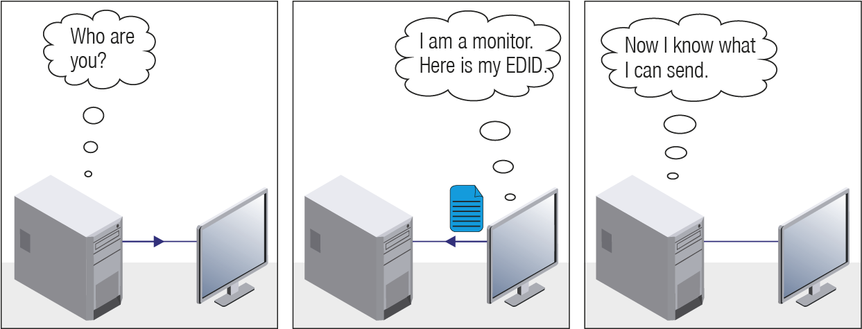
EDID Communication
Most DVI computer displays have a 128-byte long EDID structure. However, Digital Televisions and HDMI capable displays may have another 128 bytes, which is called E-EDID and defined is by CEA (Consumer Electronics Association). This extension contains information about additional Detailed Timings, audio capabilities, speaker allocation and HDMI capabilities. It is important to know that all HDMI capable devices must have CEA extension, but not all devices with CEA extension are HDMI capable.
Common Problems Related to EDID
Problem: “My system consists of the following: a computer, a Lightware device, a WUXGA (1920x1200) LCD monitor, and an SXGA (1280x1024) projector. I would like to see the same image on the monitor and the projector. What EDID should I choose on the Lightware device?”
Solution: If you want to see the image on both displays, you need to select the resolution of the smaller display (in this case SXGA), otherwise the smaller display may not show the higher resolution image.
Problem: “I have changed to a different EDID on an input port of the Lightware device to have a different resolution, but nothing happens.”
Solution: Some graphics cards and video sources read out the EDID only after power-up and later they do not sense that the EDID has been changed. You need to restart your source to make it read out the EDID again.
15.1.2. Advanced EDID Management
Each DVI sink (e.g. monitors, projectors, plasma displays, etc...) must support the EDID data structure. Source BIOS and operating systems are likely to query the sink using DDC2B protocol to determine what pixel formats and interface are supported. The DVI standard uses EDID data structure to identify the monitor type and capabilities. Most DVI sources (VGA cards, set top boxes, etc.) will output DVI signal after accepting the connected sink’s EDID information. In the case of EDID readout failure or missing EDID, the source will not output DVI video signal.
Lightware devices provide the Advanced EDID Management function that helps system integration. The built-in EDID Router can store and emulate factory pre-programmed- and User programmable EDIDs. The EDID of the attached monitors or projectors for each output is stored in a non-volatile memory. This way the EDID of a monitor is available when the monitor is unplugged or switched off.
Any EDID can be emulated on any input. An emulated EDID can be copied from the EDID router’s memory (static EDID emulation), or from the last attached monitor’s memory (dynamic EDID emulation). For example, the Lightware device can be set up to emulate a sink device that is connected to one of the outputs. In this case, the EDID automatically changes if the monitor is replaced with another display device (as long as it has a valid EDID).
EDID is independently programmable for all inputs without affecting each other. All inputs have their own EDID circuit.
INFO:The user is not required to disconnect the video cable to change an EDID as opposed to other manufacturer’s products. The EDID can be changed even if a source is connected to the input and powered ON.
INFO:When the EDID has been changed, the router toggles the HOTPLUG signal for 2 seconds. Some sources do not sense this signal. In such cases, the source device must be restarted or powered OFF and ON again.
15.2. HDCP Management
Lightware Visual Engineering is a legal HDCP adopter. Several functions have been developed that help to solve HDCP related problems. Complex AV systems often have both HDCP and non-HDCP components. The matrix allows transmitting HDCP encrypted and unencrypted signals. The devices will be still HDCP compliant, as they will never output an encrypted signal to a non-HDCP compliant display device. If an encrypted signal is switched to a non-compliant output, a red screen alert or muted screen will appear.
15.2.1. Protected and Unprotected Content
Many video sources send HDCP protected signal if they detect that the sink is HDCP capable – even if the content is not copyrighted. This can cause trouble if an HDCP capable device is connected between the source and the display. In this case, the content cannot be viewed on non-HDCP capable displays and interfaces like event controllers. Rental and staging technicians often complain about certain laptops that always send HDCP encrypted signals if the receiver device (display, matrix router, etc.) reports HDCP compliancy. However, HDCP encryption is not required all the time (e.g. computer desktop image), certain laptops still do that.
To avoid unnecessary HDCP encryption, Lightware introduced the HDCP enabling/disabling function: the HDCP capability can be disabled in the Lightware device. If HDCP is disabled, the connected source will detect that the sink is not HDCP capable, and turn off authentication.
15.2.2. Disable Unnecessary Encryption
HDCP Compliant Sink
All the devices are HDCP-compliant, no manual setting is required, both protected and unprotected contents are transmitted and displayed on the sink.
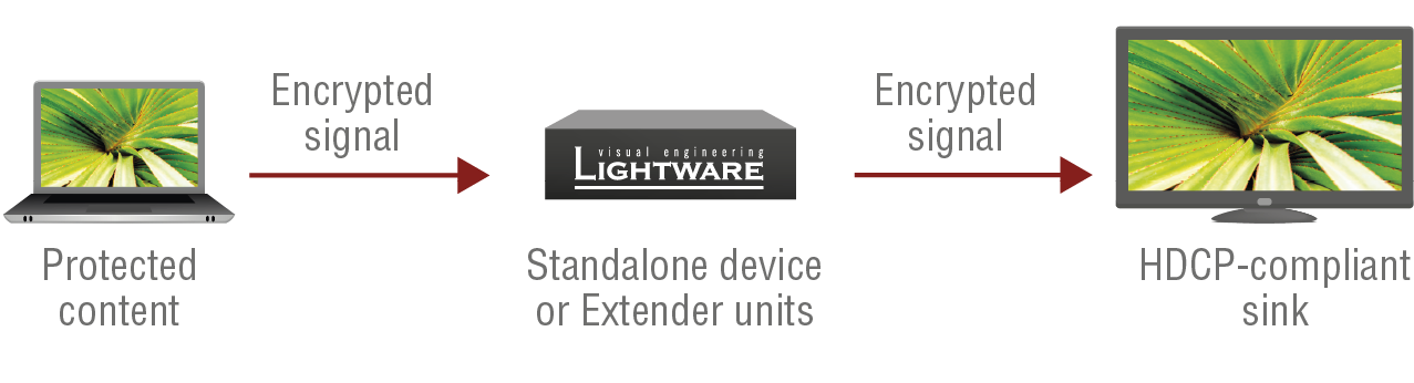
Not HDCP-compliant Sink 1.
Not-HDCP compliant sink is connected to the matrix. Some sources (e.g. computers) always send HDCP encrypted signals if the receiver device reports HDCP compliancy, however, HDCP encryption is not required all the time (e.g. computer desktop image). If HDCP is enabled in the matrix, the image will not be displayed on the sink.
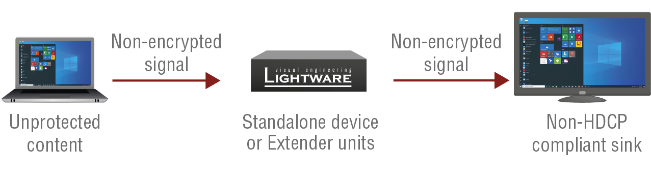
Setting the HDCP parameter to Auto on the output port and disabling HDCP on the input port, the transmitted signal will not be encrypted if the content is not protected. Thus, non-HDCP compliant sinks will display non-encrypted signal.
Not HDCP-compliant Sink 2.
The layout is the same as in the previous case: non-HDCP compliant display device is connected to the matrix, but the source would send protected content with encryption. If HDCP is enabled on the input port of the matrix, the source will send encrypted signal.
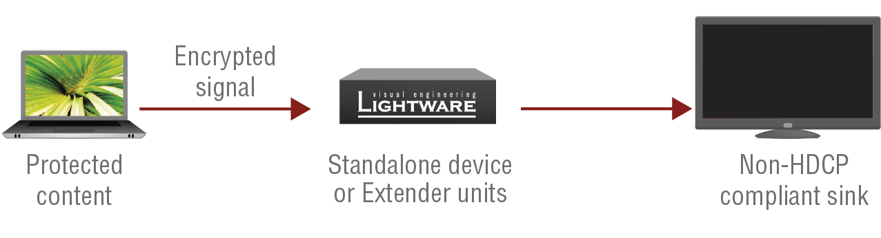
The sink is not HDCP compliant, thus it will not display the video signal (but blank/red/muted/etc. screen). If HDCP is disabled on the input port of the matrix, the source will not send the signal. The solution is to replace the display device with an HDCP-capable one.
15.2.3. HDCP 2.2
HDCP 2.2 is the latest evolution of copy protection. It is designed to create a secure connection between a source and a display. The 2.x version of HDCP is not a continuation of HDCP 1, and is rather a completely different link protection. One of the main differences is the number of the allowed devices within a closed AV system: HDCP 2.2 allows 32 devices (HDCP 1.4 allows 128 devices). Further limit is that up to four level is allowed, which means the protected signal can be transmitted over at most four repeater/matrix/switcher device. HDCP content protection is activated only if an active video stream is transmitted from the source to the display. The encryption is not activated without a video signal.
HDCP 2.2 standard allows to apply a previous version of HDCP (e.g. HDCP v1.4) between the source and the display if the source device allows it. According to the standard, if the image content is protected with HDCP, the highest supported content protection level has to be applied. However, if the highest level of protection is not justified by the source content, the level may be decreased to avoid compatibility problems; this case is determined by the source.
HDCP 2.2 Source and HDCP 1.4 Sink
In this case the signal of an HDCP 2.2 compliant source is switched to an HDCP v1.4 compliant sink device. The signal is encrypted with HDCP 2.2 on the input and encrypted with HDCP v1.4 on the output of the Lightware device. A lower level of encryption may be applied only if the source device/content allows it - according to the HDCP standard. In this case the HDCP setting on the input port has to be set to HDCP 1.4 and Depends on input on the output port.
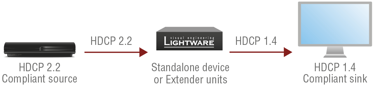
HDCP 1.4 Source and HDCP 2.2 Sink
The example below is the reversal of the previous case. An HDCP 1.4 compliant source sends a signal with HDCP 1.4 encryption. The signal is switched to an HDCP 2.2 compliant sink device. In this case the outgoing signal has to be encrypted with the highest supported encryption level towards the sink, as the Lightware device and the sink are both HDCP 2.2 compliant. The HDCP 2.2 standard does not allow keeping the original HDCP 1.4 encryption level on the output.
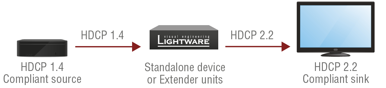
What Kind of Signal Will be on the Output of the Lightware Device?
See the table below summarizing the possible cases:
|
Incoming Signal |
HDCP 1.4 Compatible Sink |
HDCP 2.2. Compatible Sink |
|---|---|---|
|
HDCP 1.4 |
HDCP 1.4 |
HDCP 2.2 |
|
HDCP 2.2 (convertable)* |
HDCP 1.4 |
HDCP 2.2 |
|
HDCP 2.2 (not convertable)* |
Black screen |
HDCP 2.2 |
* Stream type 0: the video stream allows to convert the signal to apply a lower level of encryption.
** Stream type 1: the video stream does not allow to convert the signal.
15.3. Pixel Accurate Reclocking
Signal reclocking is an essential procedure in digital signal transmission. After passing the reclocking circuit, the signal becomes stable, jitter-free, and can be transmitted over more equipment like processors or event controllers. Without reclocking, sparkles, noise, and jaggies appear on the image.
Lightware’s sophisticated Pixel Accurate Reclocking technology fixes more problems than general TMDS reclocking. It removes not only intra-pair skew, but inter-pair skew as well. The Pixel Accurate Reclocking circuit eliminates the following errors:
Intra-pair skew
Skew between the + and - wires within a differential wire pair (e.g. Data2- and Data2+). It’s caused by different wire lengths or slightly different wire construction (impedance mismatch) in the DVI cable. It results in jitter.

Inter-pair skew
Skew between two differential wire pairs in a cable. It is caused by different wire pair lengths or different number of twists in the DVI cable. Too much inter-pair skew results in color shift in the picture or sync loss.
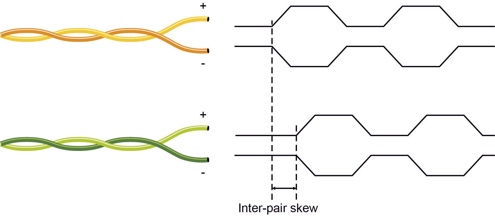
Jitter
Signal instability in the time domain. The time difference between two signal transitions should be a fixed value, but noise and other effects cause variations.

Noise
Electromagnetic interference between other electronic devices such as mobile phones, motors, etc. and the DVI cable are coupled onto the signal. Too much noise results in increased jitter.

15.4. AV Over IP
15.4.1. Basics
Besides the traditional AV matrix switchers and extenders, the AV over IP or networked AV system is the biggest leading technology in the AV industry. The spreading of the technology speeds up the general increase of the usage of the IT-related devices and equipment all around the world - from offices to homes.
The main difference compared to the traditional AV technologies is the method of the signal transmission: the networked AV transmitter/encoder devices convert the video signal to TCP/IP packets and transfer them to the receivers/decoders. The interface of the transmission can be CATx or fiber optical cable depending on the signal bandwidth and the distance between the source and sink devices.
15.4.2. What is TCP/IP?
DEFINITION:TCP/IP, or the Transmission Control Protocol/Internet Protocol, is a suite of communication protocols used to interconnect network devices on the Internet or in a private network.
TCP/IP specifies how data is exchanged over the network by providing end-to-end communications that identify how it should be broken into packets, addressed, transmitted, routed and received at the destination. TCP/IP requires little central management, and it is designed to make networks reliable, with the ability to recover automatically from the failure of any device on the network. *
The two main protocols in the Internet protocol suite serve specific functions. TCP defines how applications can create channels of communication across a network. It also manages how a message is assembled into smaller packets before they are then transmitted over the Internet and reassembled in the right order at the destination address. *
IP defines how to address and route each packet to make sure it reaches the right destination. Each gateway computer on the network checks this IP address to determine where to forward the message. *
* Source: https://searchnetworking.techtarget.com/definition/TCP-IP
15.4.3. Multicast DNS (mDNS) Protocol
The multicast DNS (mDNS - (multicast Domain Name System) protocol resolves host names to IP addresses within small networks that do not include a local name server. It is a zero-configuration service, using essentially the same programming interfaces, packet formats and operating semantics as the unicast Domain Name System (DNS). *
The primary benefits of using mDNS is that it requires little or no administration to set up. Unless the network is specifically configured to not allow mDNS, TPN sources will be discovered. This format works when no infrastructure is present, and can span infrastructure failures.
* Source: https://en.wikipedia.org/wiki/Multicast_DNS
Tables, drawings, guides, technical details and the hashtag keyword list as follows:
16.1. Specification
INFO:Specificatios are subject to change without notice.
16.1.1. HDMI-TPN Series Transmitters
Affected models:
▪HDMI-TPN-TX107
▪HDMI-TPN-TX107D
▪HDMI-TPN-TX207AU2K
▪HDMI-TPN-TX207DU2K
General
|
Compliance |
CE, UKCA |
|
EMC (emission) |
EN 55032:2015+A1:2020 |
|
EMC (immunity) |
EN 55035:2017+A11:2020 |
|
RoHS |
EN 63000:2018 |
|
Electrical safety |
EN 62368-1:2024 |
|
Laser safety |
EN 60825-1:2014+A11:2021 |
|
Warranty |
3 years |
|
Cooling |
Passive |
|
Operating temperature |
0 to +50˚C (+32 to +122˚F) |
|
Storage temperature |
-40° to +85˚C (-40° to +185˚F) |
|
Operating humidity |
10% to 90%, non-condensing |
Power
|
Power supply option |
External power adaptor |
|
Supported power source |
100-240 V AC; 50/60 Hz |
HDMI-TPN-TX107
|
Supplied power |
48V DC, 0.3A |
|
AC power plug |
Interchangable (EU, UK, JP/US, AUS/NZ) |
|
DC power plug |
2-pole Phoenix® plug |
|
Power consumption |
11.4 W |
|
Heat dissipation |
38.9 BTU/h |
HDMI-TPN-TX207AU2K and HDMI-TPN-TX107D
|
Supplied power |
12V DC, 2A |
|
AC power plug |
Interchangable (EU, UK, JP/US, AUS/NZ) |
|
DC power plug |
Locking DC connector (2.1 mm pin) |
|
Power consumption |
18 W |
|
Heat dissipation |
61.4 BTU/h |
Enclosure
HDMI-TPN-TX107
|
Rack mountable |
Yes, with mounting accessories, check the Mounting Options - Compatibility Table |
|
Enclosure material |
1 mm steel |
|
Dimensions in mm |
100.4 W x 131.8 D x 26 H |
|
Dimensions in inch |
3.95 W x 5.19 D x 1 H |
|
Weight |
476 g (1.05 lbs) |
HDMI-TPN-TX107D
|
Rack mountable |
Yes, with mounting accessories, check the Mounting Options - Compatibility Table |
|
Enclosure material |
1 mm steel |
|
Dimensions in mm |
138 W x 151.8 D x 26 H |
|
Dimensions in inch |
5.43 W x 5.97 D x 1 H |
|
Weight |
604 g (1.33 lbs) |
HDMI-TPN-TX207AU2K / HDMI-TPN-TX207DU2K
|
Rack mountable |
Yes, with mounting accessories, check the Mounting Options - Compatibility Table |
|
Enclosure material |
1 mm steel |
|
Dimensions in mm |
100.4 W x 151.8 D x 26 H |
|
Dimensions in inch |
3.95 W x 5.97 D x 1 H |
|
Weight |
528 g (1.16 lbs) |
Video Input
HDMI Input
|
Connector type |
19-pole HDMI Type A receptacle |
|
Standard |
DVI 1.0, HDMI 1.4, HDMI 2.0 |
|
Supported resolutions at 8 bits/color * |
up to 4096x2160@60Hz (4:4:4) or up to 3840x2160@60Hz (4:4:4) |
|
Audio formats |
8 channel PCM Dolby Digital, Dolby Digital Plus, Dolby TrueHD, Dolby Atmos DTS, DTS-HD Master Audio 7.1, WMA Pro |
|
CEC support |
Transparent |
Video Outputs
TPN Output
|
Connector type |
RJ45 female connector |
|
Power over Ethernet |
PoE PD (IEEE802.3af) |
|
Data rate |
10GBase-T |
|
Compliance |
SDVoE |
|
HDCP compliance |
HDCP 2.3 |
|
Transferred signals |
Video, Audio, RS-232, Infrared, Ethernet, CEC |
|
Color space |
RGB, YCbCr |
|
Video latency |
0 frame (five lines/ under 8ms) |
|
Compression ratio |
1.4 to 1 ** |
|
Supported resolutions at 8 bits/color * |
up to 4096x2160@60Hz (4:4:4) or up to 3840x2160@60Hz (4:4:4) |
|
Audio formats |
8 channel PCM Dolby Digital, Dolby Digital Plus, Dolby TrueHD, Dolby Atmos DTS, DTS-HD Master Audio 7.1, WMA Pro |
HDMI Output
|
Connector type |
19-pole HDMI Type A receptacle |
|
Standard |
DVI 1.0, HDMI 1.4, HDMI 2.0 |
|
Supported resolutions at 8 bits/color * |
up to 4096x2160@60Hz (4:4:4) or up to 3840x2160@60Hz (4:4:4) |
|
Audio formats |
8 channel PCM Dolby Digital, Dolby Digital Plus, Dolby TrueHD, Dolby Atmos DTS, DTS-HD Master Audio 7.1, WMA Pro |
|
CEC support |
Transparent |
* All standard VESA, CEA and other custom resolutions up to 600MHz (HDMI 2.0) are supported.
** Compression is applied only if the AV signal exceeds the maximum bandwidth offered by the HDMI1.4 specification.
Audio Port
Analog Audio Output
DIFFERENCE:Only for HDMI-TPN-TX207AU2K model.
|
Audio port connector |
5-pole Phoenix connector |
|
Number of ports |
1 |
|
Audio formats |
2-channel PCM |
|
Signal transmission |
Balanced signal |
|
Sampling frequency |
48 kHz |
Dante®/AES67 Output Port
DIFFERENCE:Only for HDMI-TPN-TX107D and HDMI-TPN-TX207DU2K models.
|
Number of ports |
1 |
|
Connector type |
RJ45 female connector |
|
Audio formats |
Dante® or AES67 |
|
Supported channels |
2-channel stereo |
|
Sampling rates |
44.1, 48, 88.2, 96 kHz |
Control Ports
Ethernet Port
|
Connector type |
RJ45 female connector |
|
Number of connectors per unit |
2 |
|
Ethernet data rate |
1GBase-T, full duplex with autodetect |
|
Power over Ethernet |
Not supported |
RS-232 Serial Port
|
Connector type |
3-pole Phoenix® connector |
|
Baud rates |
between 9600 and 115200 baud |
|
Data bits |
8 |
|
Parity |
None / Odd / Even |
|
Stop bits |
1 / 2 |
|
Output voltage: Low level |
3 - 15V |
|
Output voltage: High level |
-15V - 3V |
Infrared Output Port
DIFFERENCE:Only for HDMI-TPN-TX107 model.
|
Connector type |
3.5mm TRS (approx. 1/8” jack |
|
Output signal |
Modulated (38kHz) |
|
Operation mode |
Command injection (only with 3rd-party software) |
USB Ports
DIFFERENCE:Only for HDMI-TPN-TX207AU2K and HDMI-TPN-TX207DU2K models.
USB-C port
|
Connector type |
USB Type-C receptacle |
|
Number of connectors per unit |
1 |
|
USB compliance |
USB 2.0 |
|
Accepted signal |
USB data only |
USB-A port
|
Connector type |
USB Type-A receptacle |
|
Number of connectors per unit |
2 |
|
USB compliance |
USB 2.0 |
|
Power supplement of all ports |
5V, 1.4A |
|
Max current supplement per USB-A port |
1A |
16.1.2. HDMI-OPTN Series Transmitters
Affected models:
▪HDMI-OPTN-TX100A
▪HDMI-OPTN-TX200AU2K
General
|
Compliance |
CE, UKCA |
|
EMC (emission) |
EN 55032:2015+A1:2020 |
|
EMC (immunity) |
EN 55035:2017+A11:2020 |
|
RoHS |
EN 63000:2018 |
|
Electrical safety |
EN 62368-1:2024 |
|
Laser safety |
EN 60825-1:2014+A11:2021 |
|
Warranty |
3 years |
|
Cooling |
Passive |
|
Operating temperature |
0 to +50˚C (+32 to +122˚F) |
|
Storage temperature |
-40° to +85˚C (-40° to +185˚F) |
|
Operating humidity |
10% to 90%, non-condensing |
Power
|
Power supply option |
External power adaptor |
|
Supported power source |
100-240 V AC; 50/60 Hz |
|
Supplied power |
12V DC, 2A |
|
AC power plug |
Interchangable (EU, UK, JP/US, AUS/NZ) |
|
DC power plug |
Locking DC connector (2.1 mm pin) |
|
Power consumption |
6.7 W |
|
Heat dissipation |
22.9 BTU/h |
Enclosure
|
Rack mountable |
Yes, with mounting accessories, check the Mounting Options - Compatibility Table |
|
Enclosure material |
1 mm steel |
|
Dimensions in mm |
100.4 W x 151.8 D x 26 H |
|
Dimensions in inch |
3.95 W x 5.97 D x 1 H |
|
Weight |
476 g (1.05 lbs) |
Video Input
HDMI Input
|
Connector type |
19-pole HDMI Type A receptacle |
|
Standard |
DVI 1.0, HDMI 1.4, HDMI 2.0 |
|
Supported resolutions at 8 bits/color * |
up to 4096x2160@60Hz (4:4:4) or up to 3840x2160@60Hz (4:4:4) |
|
Audio formats |
8 channel PCM Dolby Digital, Dolby Digital Plus, Dolby TrueHD, Dolby Atmos DTS, DTS-HD Master Audio 7.1, WMA Pro |
|
CEC support |
Transparent |
Video Outputs
OPTN Output
|
Connector type |
SFP+ port slot |
|
Data rate |
Up to 10Gbps |
|
Accepted interfaces |
10G SFP+ optical transceiver modules 10G DAC cables |
|
Compliance |
SDVoE |
|
HDCP compliance |
HDCP 2.3 |
|
Transferred signals |
Video, Audio, RS-232, Infrared, Ethernet, CEC |
|
Color space |
RGB, YCbCr |
|
Video latency |
0 frame (five lines/ under 8ms) |
|
Compression ratio |
1.4 to 1 ** |
|
Supported resolutions at 8 bits/color * |
up to 4096x2160@60Hz (4:4:4) or up to 3840x2160@60Hz (4:4:4) |
|
Audio formats |
8 channel PCM Dolby Digital, Dolby Digital Plus, Dolby TrueHD, Dolby Atmos DTS, DTS-HD Master Audio 7.1, WMA Pro |
* All standard VESA, CEA and other custom resolutions up to 600MHz (HDMI 2.0) are supported.
** Compression is applied only if the AV signal exceeds the maximum bandwidth offered by the HDMI1.4 specification.
HDMI Output
|
Connector type |
19-pole HDMI Type A receptacle |
|
Standard |
DVI 1.0, HDMI 1.4, HDMI 2.0 |
|
Supported resolutions at 8 bits/color * |
up to 4096x2160@60Hz (4:4:4) or up to 3840x2160@60Hz (4:4:4) |
|
Audio formats |
8 channel PCM Dolby Digital, Dolby Digital Plus, Dolby TrueHD, Dolby Atmos DTS, DTS-HD Master Audio 7.1, WMA Pro |
|
CEC support |
Transparent |
* All standard VESA, CEA and other custom resolutions up to 600MHz (HDMI 2.0) are supported.
Audio Port
Analog Audio Output
|
Audio port connector |
5-pole Phoenix connector |
|
Number of ports |
1 |
|
Audio formats |
2-channel PCM |
|
Signal transmission |
Balanced signal |
|
Sampling frequency |
48 kHz |
Control Ports
Ethernet Port
|
Connector type |
RJ45 female connector |
|
Number of connectors per unit |
2 |
|
Ethernet data rate |
1GBase-T, full duplex with autodetect |
|
Power over Ethernet |
Not supported |
RS-232 Serial Port
|
Connector type |
3-pole Phoenix® connector |
|
Baud rates |
between 9600 and 115200 baud |
|
Data bits |
8 |
|
Parity |
None / Odd / Even |
|
Stop bits |
1 / 2 |
|
Output voltage: Low level |
3 - 15V |
|
Output voltage: High level |
-15V - 3V |
USB Ports
DIFFERENCE:Only for HDMI-OPTN-TX200AU2K model.
USB-C port
|
Connector type |
USB Type-C receptacle |
|
Number of connectors per unit |
1 |
|
USB compliance |
USB 2.0 |
|
Accepted signal |
USB data only |
USB-A port
|
Connector type |
USB Type-A receptacle |
|
Number of connectors per unit |
2 |
|
USB compliance |
USB 2.0 |
|
Power supplement of all ports |
5V, 1.4A |
|
Max current supplement per USB-A port |
1A |
16.1.3. HDMI-TPN Series Non-Scaling Receivers
Affected models:
▪HDMI-TPN-RX107
▪HDMI-TPN-RX107D
▪HDMI-TPN-RX107AU2K
General
|
Compliance |
CE, UKCA |
|
EMC (emission) |
EN 55032:2015+A1:2020 |
|
EMC (immunity) |
EN 55035:2017+A11:2020 |
|
RoHS |
EN 63000:2018 |
|
Electrical safety |
EN 62368-1:2024 |
|
Laser safety |
EN 60825-1:2014+A11:2021 |
|
Warranty |
3 years |
|
Cooling |
Passive |
|
Operating temperature |
0 to +50˚C (+32 to +122˚F) |
|
Storage temperature |
-40° to +85˚C (-40° to +185˚F) |
|
Operating humidity |
10% to 90%, non-condensing |
Power
|
Power supply option |
External power adaptor |
|
Supported power source |
100-240 V AC; 50/60 Hz |
HDMI-TPN-RX107
|
Supplied power |
48V DC, 0.3A |
|
AC power plug |
Interchangable (EU, UK, JP/US, AUS/NZ) |
|
DC power plug |
2-pole Phoenix® plug |
|
Power consumption |
12.8 W |
|
Heat dissipation |
43.7 BTU/h |
HDMI-TPN-RX107AU2K and HDMI-TPN-RX107D
|
Supplied power |
12V DC, 2A |
|
AC power plug |
Interchangable (EU, UK, JP/US, AUS/NZ) |
|
DC power plug |
Locking DC connector (2.1 mm pin) |
|
Power consumption |
22 W |
|
Heat dissipation |
75.1 BTU/h |
Enclosure
HDMI-TPN-RX107
|
Rack mountable |
Yes, with mounting accessories, check the Mounting Options - Compatibility Table |
|
Enclosure material |
1 mm steel |
|
Dimensions in mm |
100.4 W x 131.8 D x 26 H |
|
Dimensions in inch |
3.95 W x 5.19 D x 1 H |
|
Weight |
476 g (1.05 lbs) |
HDMI-TPN-RX107D
|
Rack mountable |
Yes, with mounting accessories, check the Mounting Options - Compatibility Table |
|
Enclosure material |
1 mm steel |
|
Dimensions in mm |
138 W x 151.8 D x 26 H |
|
Dimensions in inch |
5.43 W x 5.97 D x 1 H |
|
Weight |
604 g (1.33 lbs) |
HDMI-TPN-RX107AU2K
|
Rack mountable |
Yes, with mounting accessories, check the Mounting Options - Compatibility Table |
|
Enclosure material |
1 mm steel |
|
Dimensions in mm |
100.4 W x 151.8 D x 26 H |
|
Dimensions in inch |
3.95 W x 5.97 D x 1 H |
|
Weight |
538 g (1.19 lbs) |
Video Input
TPN Input
|
Connector type |
RJ45 female connector |
|
Power over Ethernet |
PoE PD (IEEE802.3af) |
|
Data rate |
10GBase-T |
|
Compliance |
SDVoE |
|
HDCP compliance |
HDCP 2.3 |
|
Transferred signals |
Video, Audio, RS-232, Infrared, Ethernet, CEC |
|
Color space |
RGB, YCbCr |
|
Video latency |
0 frame (five lines/ under 8ms) |
|
Compression ratio |
1.4 to 1 ** |
|
Supported resolutions at 8 bits/color * |
up to 4096x2160@60Hz (4:4:4) or up to 3840x2160@60Hz (4:4:4) |
|
Audio formats |
8 channel PCM Dolby Digital, Dolby Digital Plus, Dolby TrueHD, Dolby Atmos DTS, DTS-HD Master Audio 7.1, WMA Pro |
Video Output
HDMI Output
|
Connector type |
19-pole HDMI Type A receptacle |
|
Standard |
DVI 1.0, HDMI 1.4, HDMI 2.0 |
|
Supported resolutions at 8 bits/color * |
up to 4096x2160@60Hz (4:4:4) or up to 3840x2160@60Hz (4:4:4) |
|
Audio formats |
8 channel PCM Dolby Digital, Dolby Digital Plus, Dolby TrueHD, Dolby Atmos DTS, DTS-HD Master Audio 7.1, WMA Pro |
|
CEC support |
Transparent |
* All standard VESA, CEA and other custom resolutions up to 600MHz (HDMI 2.0) are supported.
** Compression is applied only if the AV signal exceeds the maximum bandwidth offered by the HDMI1.4 specification.
Audio Port
DIFFERENCE:Only for HDMI-TPN-RX107AU2K model.
Analog Audio Output
|
Audio port connector |
5-pole Phoenix connector |
|
Number of ports |
1 |
|
Audio formats |
2-channel PCM |
|
Signal transmission |
Balanced signal |
|
Sampling frequency |
48 kHz |
Dante®/AES67 Output Port
DIFFERENCE:Only for HDMI-TPN-RX107D model.
|
Number of ports |
1 |
|
Connector type |
RJ45 female connector |
|
Audio formats |
Dante® or AES67 |
|
Supported channels |
2-channel stereo |
|
Sampling rates |
44.1, 48, 88.2, 96 kHz |
Control Ports
Ethernet Port
|
Connector type |
RJ45 female connector |
|
Number of connectors per unit |
2 |
|
Ethernet data rate |
1GBase-T, full duplex with autodetect |
|
Power over Ethernet |
Not supported |
RS-232 Serial Port
|
Connector type |
3-pole Phoenix® connector |
|
Baud rates |
between 9600 and 115200 baud |
|
Data bits |
8 |
|
Parity |
None / Odd / Even |
|
Stop bits |
1 / 2 |
|
Output voltage: Low level |
3 - 15V |
|
Output voltage: High level |
-15V - 3V |
Infrared Output Port
DIFFERENCE:Only for HDMI-TPN-RX107 model.
|
Connector type |
3.5mm TRS (approx. 1/8” jack |
|
Output signal |
Modulated (38kHz) |
|
Operation mode |
Command injection (only with 3rd-party software) |
USB Ports
DIFFERENCE:Only for HDMI-TPN-RX107AU2K model.
USB-A port
|
Connector type |
USB Type-A receptacle |
|
Number of connectors per unit |
6 |
|
USB compliance |
USB 2.0 |
|
Power supplement of USB 2.0 ports |
5V, 1.7A |
|
Power supplement of USB HID ports |
5V, 0.3A |
|
Max current supplement per USB-A port |
1A |
16.1.4. HDMI-TPN Series Scaling Receivers
Affected models:
▪HDMI-TPN-RX107A-SR
▪HDMI-TPN-RX107D-SR
▪HDMI-TPN-RX107AU2K-SR
▪HDMI-TPN-RX107DU2K-SR
General
|
Compliance |
CE, UKCA |
|
EMC (emission) |
EN 55032:2015+A1:2020 |
|
EMC (immunity) |
EN 55035:2017+A11:2020 |
|
RoHS |
EN 63000:2018 |
|
Electrical safety |
EN 62368-1:2024 |
|
Laser safety |
EN 60825-1:2014+A11:2021 |
|
Warranty |
3 years |
|
Cooling |
Passive |
|
Operating temperature |
0 to +50˚C (+32 to +122˚F) |
|
Storage temperature |
-40° to +85˚C (-40° to +185˚F) |
|
Operating humidity |
10% to 90%, non-condensing |
Power
|
Power supply option |
External power adaptor |
|
Supported power source |
100-240 V AC; 50/60 Hz |
|
Supplied power |
12V DC, 2A |
|
AC power plug |
Interchangable (EU, UK, JP/US, AUS/NZ) |
|
DC power plug |
Locking DC connector (2.1 mm pin) |
|
Power consumption |
22 W |
|
Heat dissipation |
75.1 BTU/h |
Enclosure
HDMI-TPN-RX107A-SR and HDMI-TPN-RX107D-SR
|
Rack mountable |
Yes, with mounting accessories, check the Mounting Options - Compatibility Table |
|
Enclosure material |
1 mm steel |
|
Dimensions in mm |
138 W x 151.8 D x 26 H |
|
Dimensions in inch |
5.43 W x 5.97 D x 1 H |
|
Weight |
604 g (1.33 lbs) |
HDMI-TPN-RX107AU2K-SR and HDMI-TPN-RX107DU2K-SR
|
Rack mountable |
Yes, with mounting accessories, check the Mounting Options - Compatibility Table |
|
Enclosure material |
1 mm steel |
|
Dimensions in mm |
138 W x 151.8 D x 26 H |
|
Dimensions in inch |
5.43 W x 5.97 D x 1 H |
|
Weight |
646 g (1.42 lbs) |
Video Input
TPN Input
|
Connector type |
RJ45 female connector |
|
Power over Ethernet |
PoE PD (IEEE802.3af) |
|
Data rate |
10GBase-T |
|
Compliance |
SDVoE |
|
HDCP compliance |
HDCP 2.3 |
|
Transferred signals |
Video, Audio, RS-232, Infrared, Ethernet, CEC |
|
Color space |
RGB, YCbCr |
|
Video latency |
0 frame (five lines/ under 8ms) |
|
Compression ratio |
1.4 to 1 ** |
|
Supported resolutions at 8 bits/color * |
up to 4096x2160@60Hz (4:4:4) or up to 3840x2160@60Hz (4:4:4) |
|
Audio formats |
8 channel PCM Dolby Digital, Dolby Digital Plus, Dolby TrueHD, Dolby Atmos DTS, DTS-HD Master Audio 7.1, WMA Pro |
* All standard VESA, CEA and other custom resolutions up to 600MHz (HDMI 2.0) are supported.
** Compression is applied only if the AV signal exceeds the maximum bandwidth offered by the HDMI1.4 specification.
Video Output
HDMI Output
|
Connector type |
19-pole HDMI Type A receptacle |
|
Standard |
DVI 1.0, HDMI 1.4, HDMI 2.0 |
|
Supported resolutions at 8 bits/color * |
up to 4096x2160@60Hz (4:4:4) or up to 3840x2160@60Hz (4:4:4) |
|
Audio formats |
8 channel PCM Dolby Digital, Dolby Digital Plus, Dolby TrueHD, Dolby Atmos DTS, DTS-HD Master Audio 7.1, WMA Pro |
|
CEC support |
Transparent |
Audio Port
Analog Audio Output
DIFFERENCE:Only for HDMI-TPN-RX107A-SR and HDMI-TPN-RX107AU2K-SR models.
|
Audio port connector |
5-pole Phoenix connector |
|
Number of ports |
1 |
|
Audio formats |
2-channel PCM |
|
Signal transmission |
Balanced signal |
|
Sampling frequency |
48 kHz |
Dante®/AES67 Output Port
DIFFERENCE:Only for HDMI-TPN-RX107D-SR and HDMI-TPN-RX107DU2K-SR models.
|
Number of ports |
1 |
|
Connector type |
RJ45 female connector |
|
Audio formats |
Dante® or AES67 |
|
Supported channels |
2-channel stereo |
|
Sampling rates |
44.1, 48, 88.2, 96 kHz |
Control Ports
Ethernet Port
|
Connector type |
RJ45 female connector |
|
Number of connectors per unit |
2 |
|
Ethernet data rate |
1GBase-T, full duplex with autodetect |
|
Power over Ethernet |
Not supported |
RS-232 Serial Port
|
Connector type |
3-pole Phoenix® connector |
|
Baud rates |
between 9600 and 115200 baud |
|
Data bits |
8 |
|
Parity |
None / Odd / Even |
|
Stop bits |
1 / 2 |
|
Output voltage: Low level |
3 - 15V |
|
Output voltage: High level |
-15V - 3V |
USB Ports
DIFFERENCE:Only for HDMI-TPN-RX107AU2K-SR and HDMI-TPN-RX107DU2K-SR models.
USB-A port
|
Connector type |
USB Type-A receptacle |
|
Number of connectors per unit |
6 |
|
USB compliance |
USB 2.0 |
|
Power supplement of USB 2.0 ports |
5V, 1.7A |
|
Power supplement of USB HID ports |
5V, 0.3A |
|
Max current supplement per USB-A port |
1A |
16.1.5. HDMI-OPTN Series Non-Scaling Receivers
Affected models:
▪HDMI-OPTN-RX100A
▪HDMI-OPTN-RX100AU2K
General
|
Compliance |
CE, UKCA |
|
EMC (emission) |
EN 55032:2015+A1:2020 |
|
EMC (immunity) |
EN 55035:2017+A11:2020 |
|
RoHS |
EN 63000:2018 |
|
Electrical safety |
EN 62368-1:2024 |
|
Laser safety |
EN 60825-1:2014+A11:2021 |
|
Warranty |
3 years |
|
Cooling |
Passive |
|
Operating temperature |
0 to +50˚C (+32 to +122˚F) |
|
Storage temperature |
-40° to +85˚C (-40° to +185˚F) |
|
Operating humidity |
10% to 90%, non-condensing |
Power
|
Power supply option |
External power adaptor |
|
Supported power source |
100-240 V AC; 50/60 Hz |
|
Supplied power |
12V DC, 2A |
|
AC power plug |
Interchangable (EU, UK, JP/US, AUS/NZ) |
|
DC power plug |
Locking DC connector (2.1 mm pin) |
|
Power consumption |
7.3 W |
|
Heat dissipation |
24.9 BTU/h |
Enclosure
|
Rack mountable |
Yes, with mounting accessories, check the Mounting Options - Compatibility Table |
|
Enclosure material |
1 mm steel |
|
Dimensions in mm |
100.4 W x 151.8 D x 26 H |
|
Dimensions in inch |
3.95 W x 5.97 D x 1 H |
|
Weight |
476 g (1.05 lbs) |
Video Input
OPTN Input
|
Connector type |
SFP+ port slot |
|
Data rate |
Up to 10Gbps |
|
Accepted interfaces |
10G SFP+ optical transceiver modules 10G DAC cables |
|
Compliance |
SDVoE |
|
HDCP compliance |
HDCP 2.3 |
|
Transferred signals |
Video, Audio, RS-232, Infrared, Ethernet, CEC |
|
Color space |
RGB, YCbCr |
|
Video latency |
0 frame (five lines/ under 8ms) |
|
Compression ratio |
1.4 to 1 ** |
|
Supported resolutions at 8 bits/color * |
up to 4096x2160@60Hz (4:4:4) or up to 3840x2160@60Hz (4:4:4) |
|
Audio formats |
8 channel PCM Dolby Digital, Dolby Digital Plus, Dolby TrueHD, Dolby Atmos DTS, DTS-HD Master Audio 7.1, WMA Pro |
* All standard VESA, CEA and other custom resolutions up to 600MHz (HDMI 2.0) are supported.
** Compression is applied only if the AV signal exceeds the maximum bandwidth offered by the HDMI1.4 specification.
Video Output
HDMI Output
|
Connector type |
19-pole HDMI Type A receptacle |
|
Standard |
DVI 1.0, HDMI 1.4, HDMI 2.0 |
|
Supported resolutions at 8 bits/color * |
up to 4096x2160@60Hz (4:4:4) or up to 3840x2160@60Hz (4:4:4) |
|
Audio formats |
8 channel PCM Dolby Digital, Dolby Digital Plus, Dolby TrueHD, Dolby Atmos DTS, DTS-HD Master Audio 7.1, WMA Pro |
|
CEC support |
Transparent |
* All standard VESA, CEA and other custom resolutions up to 600MHz (HDMI 2.0) are supported.
Audio Port
Analog Audio Output
|
Audio port connector |
5-pole Phoenix connector |
|
Number of ports |
1 |
|
Audio formats |
2-channel PCM |
|
Signal transmission |
Balanced signal |
|
Sampling frequency |
48 kHz |
Control Ports
Ethernet Port
|
Connector type |
RJ45 female connector |
|
Number of connectors per unit |
2 |
|
Ethernet data rate |
1GBase-T, full duplex with autodetect |
|
Power over Ethernet |
Not supported |
RS-232 Serial Port
|
Connector type |
3-pole Phoenix® connector |
|
Baud rates |
between 9600 and 115200 baud |
|
Data bits |
8 |
|
Parity |
None / Odd / Even |
|
Stop bits |
1 / 2 |
|
Output voltage: Low level |
3 - 15V |
|
Output voltage: High level |
-15V - 3V |
USB Ports
DIFFERENCE:Only for HDMI-TPN-RX107AU2K-SR model.
USB-A port
|
Connector type |
USB Type-A receptacle |
|
Number of connectors per unit |
6 |
|
USB compliance |
USB 2.0 |
|
Power supplement of USB 2.0 ports |
5V, 1.7A |
|
Power supplement of USB HID ports |
5V, 0.3A |
|
Max current supplement per USB-A port |
1A |
16.1.6. HDMI-OPTN Series Scaling Receivers
Affected models:
▪HDMI-OPTN-RX100A-SR
▪HDMI-OPTN-RX100AU2K-SR
General
|
Compliance |
CE, UKCA |
|
EMC (emission) |
EN 55032:2015+A1:2020 |
|
EMC (immunity) |
EN 55035:2017+A11:2020 |
|
RoHS |
EN 63000:2018 |
|
Electrical safety |
EN 62368-1:2024 |
|
Laser safety |
EN 60825-1:2014+A11:2021 |
|
Warranty |
3 years |
|
Cooling |
Passive |
|
Operating temperature |
0 to +50˚C (+32 to +122˚F) |
|
Storage temperature |
-40° to +85˚C (-40° to +185˚F) |
|
Operating humidity |
10% to 90%, non-condensing |
Power
|
Power supply option |
External power adaptor |
|
Supported power source |
100-240 V AC; 50/60 Hz |
|
Supplied power |
12V DC, 2A |
|
AC power plug |
Interchangable (EU, UK, JP/US, AUS/NZ) |
|
DC power plug |
Locking DC connector (2.1 mm pin) |
|
Power consumption |
13 W |
|
Heat dissipation |
44.4 BTU/h |
Enclosure
HDMI-OPTN-RX100A-SR
|
Rack mountable |
Yes, with mounting accessories, check the Mounting Options - Compatibility Table |
|
Enclosure material |
1 mm steel |
|
Dimensions in mm |
138 W x 151.8 D x 26 H |
|
Dimensions in inch |
5.43 W x 5.97 D x 1 H |
|
Weight |
604 g (1.33 lbs) |
HDMI-OPTN-RX100AU2K-SR
|
Rack mountable |
Yes, with mounting accessories, check the Mounting Options - Compatibility Table |
|
Enclosure material |
1 mm steel |
|
Dimensions in mm |
138 W x 151.8 D x 26 H |
|
Dimensions in inch |
5.43 W x 5.97 D x 1 H |
|
Weight |
646 g (1.42 lbs) |
Video Input
OPTN Input
|
Connector type |
SFP+ port slot |
|
Data rate |
Up to 10Gbps |
|
Accepted interfaces |
10G SFP+ optical transceiver modules 10G DAC cables |
|
Compliance |
SDVoE |
|
HDCP compliance |
HDCP 2.3 |
|
Transferred signals |
Video, Audio, RS-232, Infrared, Ethernet, CEC |
|
Color space |
RGB, YCbCr |
|
Video latency |
0 frame (five lines/ under 8ms) |
|
Compression ratio |
1.4 to 1 ** |
|
Supported resolutions at 8 bits/color * |
up to 4096x2160@60Hz (4:4:4) or up to 3840x2160@60Hz (4:4:4) |
|
Audio formats |
8 channel PCM Dolby Digital, Dolby Digital Plus, Dolby TrueHD, Dolby Atmos DTS, DTS-HD Master Audio 7.1, WMA Pro |
* All standard VESA, CEA and other custom resolutions up to 600MHz (HDMI 2.0) are supported.
** Compression is applied only if the AV signal exceeds the maximum bandwidth offered by the HDMI1.4 specification.
Video Output
HDMI Output
|
Connector type |
19-pole HDMI Type A receptacle |
|
Standard |
DVI 1.0, HDMI 1.4, HDMI 2.0 |
|
Supported resolutions at 8 bits/color * |
up to 4096x2160@60Hz (4:4:4) or up to 3840x2160@60Hz (4:4:4) |
|
Audio formats |
8 channel PCM Dolby Digital, Dolby Digital Plus, Dolby TrueHD, Dolby Atmos DTS, DTS-HD Master Audio 7.1, WMA Pro |
|
CEC support |
Transparent |
Audio Port
Analog Audio Output
|
Audio port connector |
5-pole Phoenix connector |
|
Number of ports |
1 |
|
Audio formats |
2-channel PCM |
|
Signal transmission |
Balanced signal |
|
Sampling frequency |
48 kHz |
Control Ports
Ethernet Port
|
Connector type |
RJ45 female connector |
|
Number of connectors per unit |
2 |
|
Ethernet data rate |
1GBase-T, full duplex with autodetect |
|
Power over Ethernet |
Not supported |
RS-232 Serial Port
|
Connector type |
3-pole Phoenix® connector |
|
Baud rates |
between 9600 and 115200 baud |
|
Data bits |
8 |
|
Parity |
None / Odd / Even |
|
Stop bits |
1 / 2 |
|
Output voltage: Low level |
3 - 15V |
|
Output voltage: High level |
-15V - 3V |
USB Ports
DIFFERENCE:Only for HDMI-OPTN-RX100AU2K-SR model.
USB-A port
|
Connector type |
USB Type-A receptacle |
|
Number of connectors per unit |
6 |
|
USB compliance |
USB 2.0 |
|
Power supplement of USB 2.0 ports |
5V, 1.7A |
|
Power supplement of USB HID ports |
5V, 0.3A |
|
Max current supplement per USB-A port |
1A |
16.1.7. TPN Control Unit
Affected model:
▪TPN-CTU-X50
General
|
Compliance |
CE, UKCA |
|
EMC (emission) |
EN 55032:2015+A1:2020 |
|
EMC (immunity) |
EN 55035:2017+A11:2020 |
|
RoHS |
EN 63000:2018 |
|
Electrical safety |
EN 62368-1:2024 |
|
Laser safety |
EN 60825-1:2014+A11:2021 |
|
Warranty |
3 years |
|
Cooling |
Passive |
|
Operating temperature |
0 to +50˚C (+32 to +122˚F) |
|
Storage temperature |
-40° to +85˚C (-40° to +185˚F) |
|
Operating humidity |
10% to 90%, non-condensing |
Power
|
Power supply option |
Power adaptor |
|
Supported power source |
100-240 V AC; 50/60 Hz |
|
Supplied power |
5V DC, 3A |
|
AC power plug |
Interchangable (EU, UK, JP/US, AUS/NZ) |
|
DC power plug |
2-pole Phoenix plug |
|
Power consumption (max) |
7.5 W |
|
Heat dissipation (max) |
26 BTU/h |
Enclosure
|
Rack mountable |
Yes, with mounting accessories, check the Mounting Options - Compatibility Table |
|
Enclosure material |
1 mm steel |
|
Dimensions in mm |
221 W x 68.3 D x 26 H |
|
Dimensions in inch |
8.7 W x 2.7 D x 1.02 H |
|
Weight |
448 g (0.99 lbs) |
Control Ports
Ethernet port
|
Connector type |
RJ45 female connector |
|
Ethernet data rate |
10/100Base-T, full duplex with autodetect |
|
Power over Ethernet (PoE) |
Not supported |
GPIO port
|
Connector type |
8-pole Phoenix |
|
Function (pin 1-6) |
Configurable (input/output) |
|
Function (pin 7) |
5V output |
|
Function (pin 8) |
Ground |
OCS port
|
Connector type |
3-pole Reversed Gender Plug Phoenix connector |
|
Number of configurable pins |
1 |
|
Port direction |
Input |
USB port (reserved for future developments)
|
Connector type |
A-type and B-type receptacles |
RS-232 port
|
Connector type |
3-pole Phoenix connector |
|
Baud rates |
between 9600 and 115200 baud |
|
Data bits |
8 |
|
Parity |
None / Odd / Even |
|
Stop bits |
1 / 2 |
|
Output voltage: Low level |
3 - 15V |
|
Output voltage: High level |
-15V - 3V |
16.2.1. CATx Cable Extension for TPN
Lightware highly recommends using CAT6a AWG24 or higher category 10G Ethernet cables for the TPN (SDVoE) connection between the transmitter/receiver and the network switch. Usage of e.g. AWG28 Ethernet cables may reduce the extension distance significantly.
|
Resolution |
CATx |
|
CAT6a AWG24 |
|
|
All resolutions |
100 m |
16.2.2. Fiber Optical Extension for OPTN
The maximum fiber cable extension of the OPTN series endpoint devices depend on the installed SFP+ module. Always read the specification of the module.
|
Multimode fiber optical cables |
Singlemode fiber optical cables |
||||
|
OM1 |
OM2 |
OM3 |
OM4 |
OS1 |
OS2 |
|
(62.5/125) |
(50/125) |
(50/125) |
(50/125) |
(62.5/125) |
(50/125) |
|
Not supported |
300 m |
400 m |
2000 m |
10000 m |
|
Ethernet Ports
|
Port name |
Port nr. (LW3) |
|
Secure Eth 1 |
P1 |
|
Utility Eth 2 |
P2 |
|
Utility Eth 3 |
P3 |
GPIO
|
Port name |
Port nr. (LW3) |
|
GPIO1 |
P1 |
|
GPIO2 |
P2 |
|
GPIO3 |
P3 |
|
GPIO4 |
P4 |
|
GPIO5 |
P5 |
|
GPIO6 |
P6 |
OCS
|
Port name |
Port nr. (LW3) |
|
OCS1 |
P1 |
RS-232 Ports
|
Port name |
Port nr. |
Serial over IP port nr. |
|
RS-232 1 |
P1 |
8001 |
|
RS-232 2 |
P2 |
8002 |
16.4. Factory Default Settings
TPN-CTU-X50
|
Parameter |
Value |
|
Network settings |
|
|
Factory default IP address mode |
DHCP |
|
Static IP address |
192.168.0.100 |
|
Static network mask |
255.255.255.0 |
|
Static gateway address |
192.168.0.1 |
|
Hostname |
lightware-<serialno> |
|
LW3 protocol |
enabled |
|
HTTP, HTTPS |
enabled |
|
HTTP, HTTPS authentication |
disabled |
|
Authentication setting (user/password) |
admin/<not set> |
|
RS-232 port settings |
|
|
RS-232 port |
9600 BAUD, 8, N, 1 |
|
RS-232 serial over IP |
enabled |
|
GPIO port settings |
|
|
Output level /direction |
low / input |
|
Occupancy sensor |
|
|
Sensor type |
active high |
|
Miscellaneous |
|
|
Control lock |
disabled |
|
Dark mode |
disabled |
|
Automatic fan control |
enabled |
16.5. Content of the Backup File (Clone Configuration)
The backup file contains numerous settings and parameters saved from the device. When the file is uploaded to a device, the following will be overwritten:
|
Local serial port |
|
Port name, RS-232 mode, Control protocol, Baud rate, Data bits, Stop bits, Parity |
|
GPIO port |
|
Port name, Direction, Level |
|
OCS port |
|
Sensor type, Port name |
|
Network settings |
|
Port name, Port status. PHY (speed and duplexity) mode |
|
HTTP/HTTPS port status, HTTP/HTTPS Authentication status |
|
LW3 port status, Serial port status |
|
Authentication (password) |
|
LARA configuration |
|
All drivers, instances, parameters, configuration settings and data |
|
Further settings |
|
Control lock status, Device label, Dark mode state, Dark mode delay |
|
Welcome screen status, Welcome screen parameters |
INFO:See more details about the configuration cloning in the System section.
16.6. Reserved Ports and Security Options
The following table summarizes the ports, protocols, features and the security options.
|
Port number |
Protocol |
Function |
Affected device |
Affected software |
Port disable option |
Encryption |
Authentication |
Other features |
|
|---|---|---|---|---|---|---|---|---|---|
|
CTU |
Endpoints |
||||||||
|
80 |
TCP |
HTTP port (LW3 over WS, REST API, LARA user panels) |
|
|
LDC, LDU2 |
|
|
|
Firmware update, Welcome Screen image upload, Log files, User Scripts Serial messaging |
|
443 |
TCP |
HTTPS port (LW3 over WSS, REST API, LARA management GUI) |
|
|
LDC, LDU2 |
|
|
|
|
|
6107 |
TCP |
LW3 protocol |
|
|
LDC |
|
|
|
|
|
69 |
UDP |
Firmware update TFTP |
|
|
LDU2 |
|
|
|
|
|
49990 |
UDP |
|
|
|
|
|
|||
|
49995 |
UDP |
|
|
|
|
|
|||
|
10004 |
UDP |
|
|
|
|
|
|||
|
8001, 8002 |
TCP |
Serial over IP (RS-232) |
|
|
- |
|
|
|
|
|
6108 |
TCP |
Lightware Multicast Device Management (LMDM) |
|
|
- |
|
|
|
|
|
6970 |
TCP |
TCI API protocol |
|
|
BlueRiver Control Server |
|
|
|
|
|
8080 |
TCP |
REST API and websocket |
|
|
|
|
|
||
|
230.76.87.82:37422 |
UDP |
Lightware Multicast Device Protocol (LMDP) |
|
|
- |
|
|
|
|
|
10001, 10002, 10003, 10004 |
UDP |
Serial / Infrared messages between the endpoints and CTU |
|
|
- |
|
|
|
|
|
6137, 6971 |
UDP |
USB 2.0 discovery |
|
|
- |
|
|
|
|
|
6973 |
UDP |
USB KVM connection between the AU2K series endpoints |
|
|
- |
|
|
|
|
|
6969 |
UDP |
Communication between the API server and the endpoints |
|
|
- |
|
|
|
|
|
224.0.1.188:1900 |
UDP |
SSDP messaging between the BlueRiver SDP and the endpoint devices |
|
|
- |
|
|
|
|
|
224.0.0.251: 5353 |
UDP |
mDNS /Bonjour (Device Discovery) |
|
|
LDC, LDU2 |
|
|
|
|
|
230.76.87.82: 37421 |
UDP |
Remote IP |
|
|
LDC, LDU2 |
|
|
|
|
INFO:The ports are necessary to be passed via a network switch/firewall for proper operation between the device and the softwares.
INFO:The AU2K endpoint models are built with two separated network boards with two MAC addresses and two IP addresses. In case of dynamic IP address (DHCP) setting, one device will reserve two different IP addresses.
16.7. Mechanical Drawings
16.7.1. HDMI-TPN-107 Series Endpoint Devices
The following drawings present the physical dimensions of the HDMI-TPN-107 series endpoints. Dimensions are in mm.
Affected models:
▪HDMI-TPN-TX107, -RX107
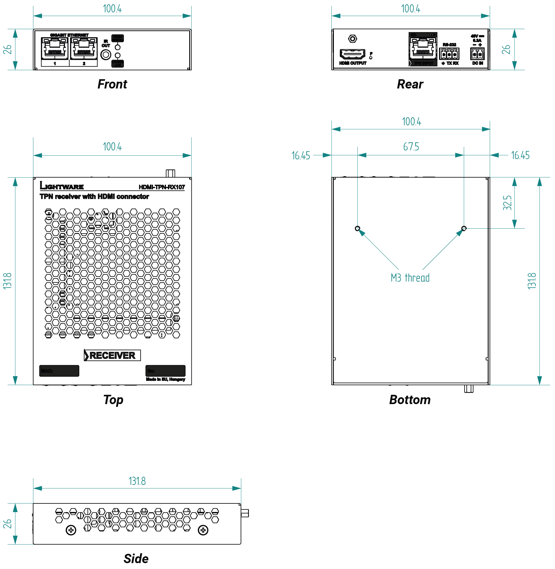
16.7.2. HDMI-AU2K Series Endpoint Devices
The following drawings present the physical dimensions of the HDMI-AU2K series endpoints. Dimensions are in mm.
Affected models:
▪HDMI-TPN-TX207AU2K, -RX107AU2K
▪HDMI-OPTN-TX100A, -RX100A, -TX200AU2K, -RX100AU2K
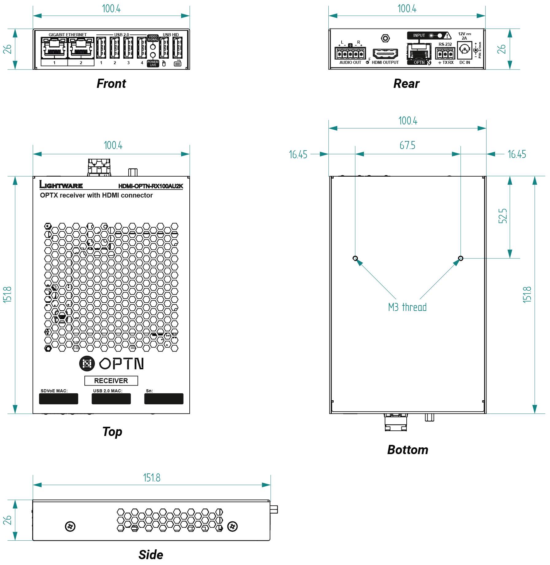
16.7.3. HDMI-TPN-SR Series Endpoint Devices
The following drawings present the physical dimensions of the HDMI-TPN-SR and HDMI-OPTN-SR series endpoints. Dimensions are in mm.
Affected models:
▪HDMI-TPN-RX107A-SR, HDMI-TPN-RX107AU2K-SR
▪HDMI-TPN-TX207DU2K, HDMI-TPN-RX107D-SR, HDMI-TPN-RX107DU2K-SR
▪HDMI-OPTN-RX100A-SR, HDMI-OPTN-RX100AU2K-SR
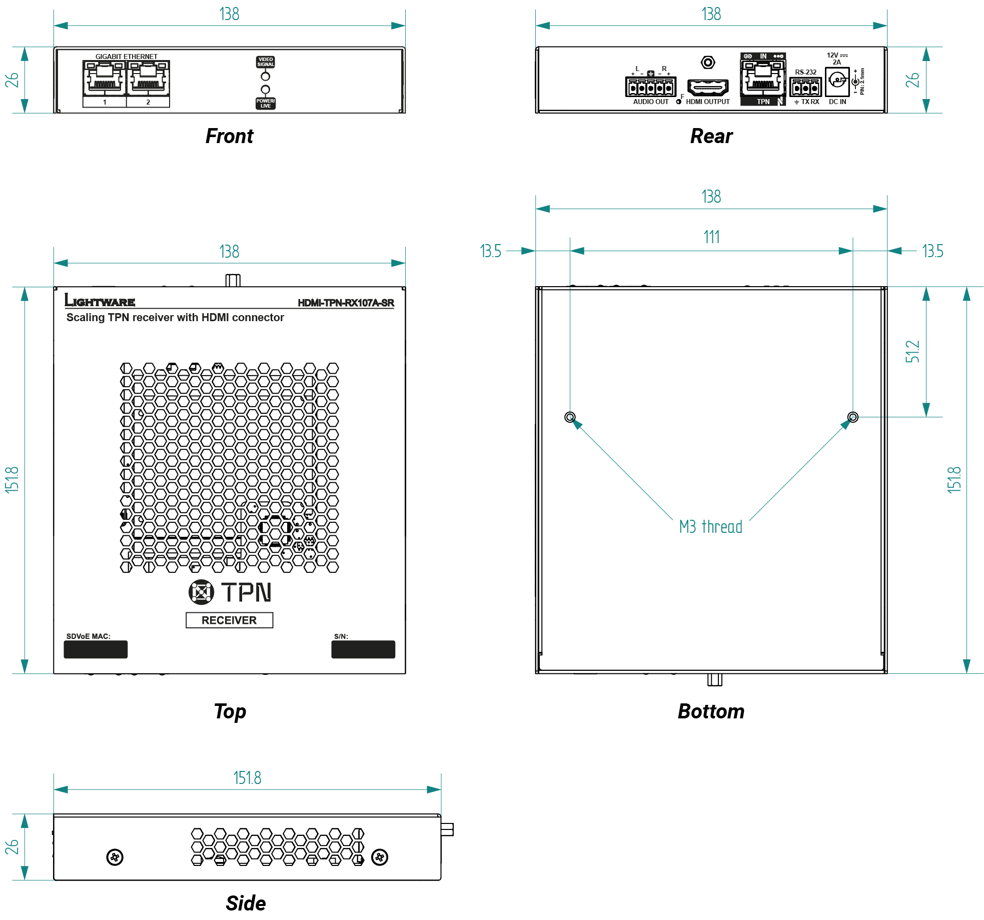
16.7.4. TPN Control Unit
The following drawings present the physical dimensions of the TPN-CTU-X50 control unit. Dimensions are in mm.
Affected model:
▪TPN-CTU-X50
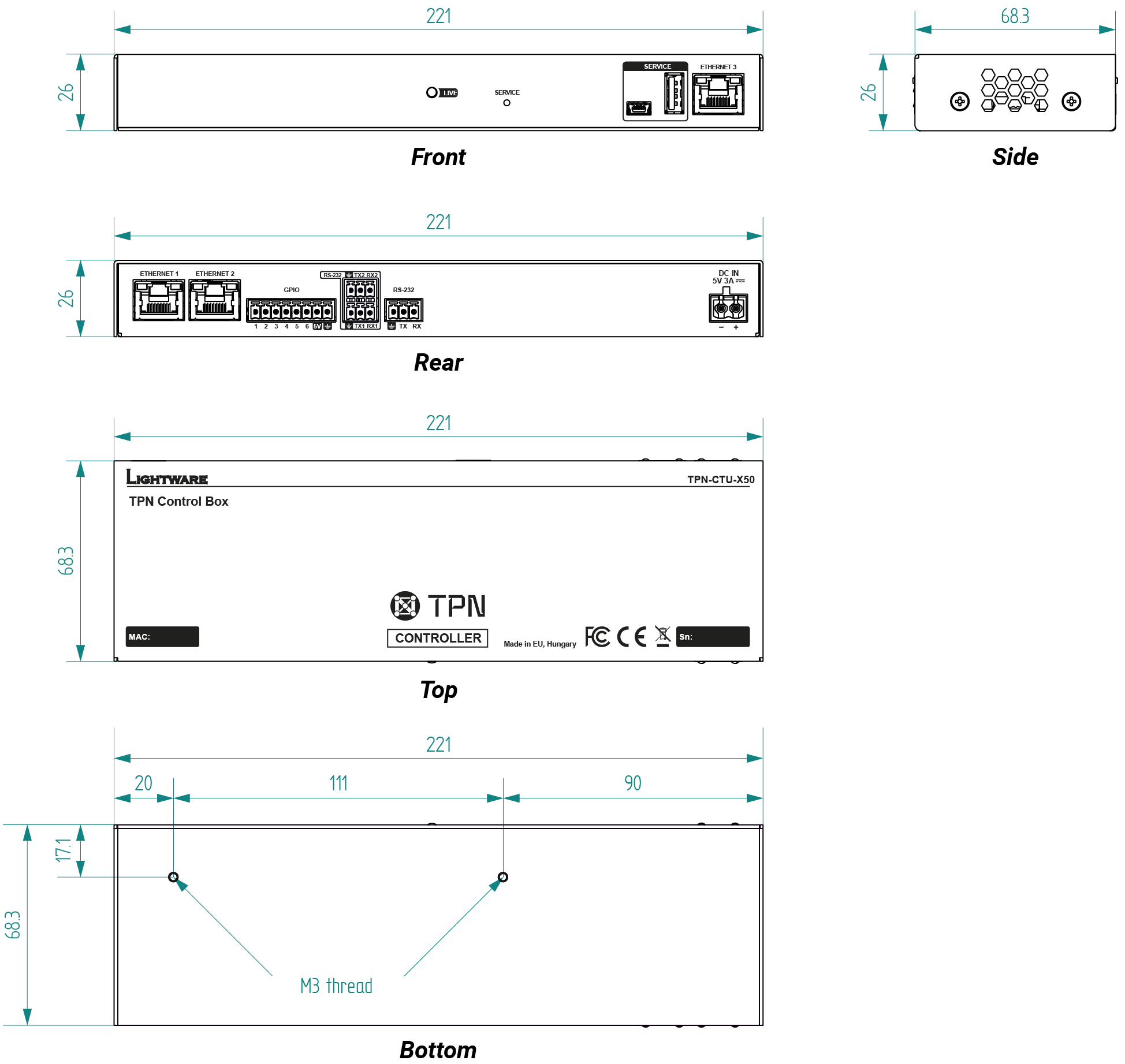
The device is built with a 3-pole Phoenix connector. See the examples below of connecting to a DCE (Data Circuit-terminating Equipment) or a DTE (Data Terminal Equipment) type device:
|
Lightware device and a DCE D-SUB 9 and Phoenix |
Lightware device and a DTE D-SUB 9 and Phoenix |
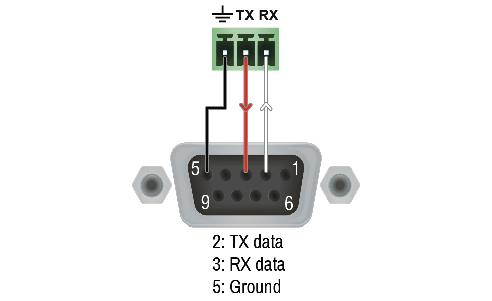
|
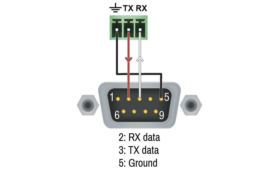
|
16.8.2. Audio Ports
Inputs and outputs of audio devices are symmetric or asymmetric. The main advantage of the symmetric lines is the better protection against the noise, therefore they are widely used in the professional audio industry. Symmetric audio is most often referred to as balanced audio, as opposed to asymmetric, which is referred to as unbalanced audio. Ligthware products are usually built with 5-pole Phoenix connectors, so we would like to help users assembling their own audio cables. See the most common cases below.
ATTENTION!Symmetric and asymmetric lines can be linked with passive accessories (e.g. special cables), but in this case half of the line level is lost.
ATTENTION!There are numerous types of regularly used connector and cable types to connect audio devices. Please always make sure that a connector or cable fits your system before use.
ATTENTION!Never join the phase-inverted (negative, cold or -) poles (either right and left) to the ground or to each other on the output side, as this can damage the unit.
INFO:Use a galvanic isolation in case of a ground loop.
The Pinout of the 5-pole Phoenix Connector
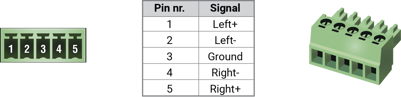
Compatible Plug Type: Phoenix® Combicon series (3.5mm pitch, 5-pole), type: MC 1.5/5-ST-3.5.
From Balanced Output to Unbalanced Input
|
Phoenix - 2 x 6.3 (1/4") TS |
Phoenix - 2 x RCA |
Phoenix - 3.5 (1/8") TRS |
||
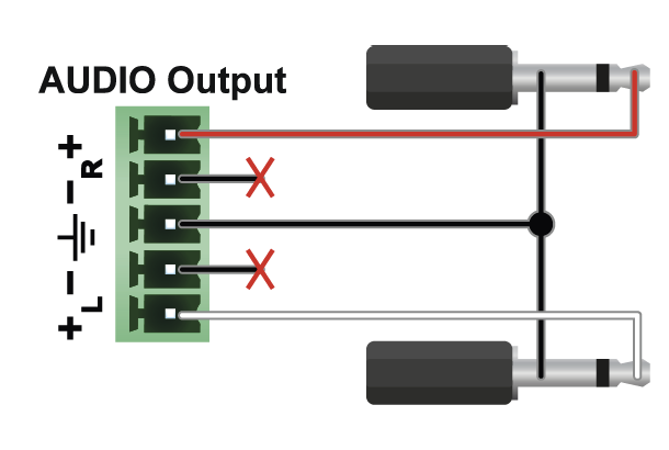
|
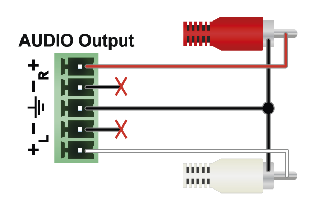
|
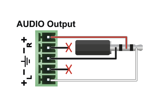
|
From Balanced Output to Balanced Input
|
Phoenix - 2 x 6.3 (1/4") TRS |
Phoenix - 2 x XLR |
|
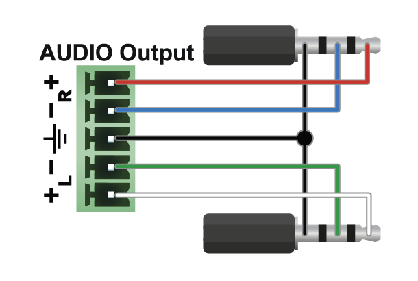
|
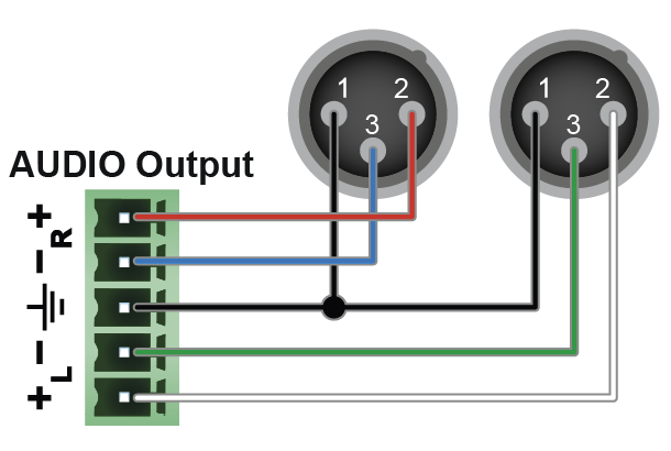
|
The switcher is supplied with a 3.81mm 3-pole 90° Reversed Gender Plug Phoenix® connector, which is used for connecting an occupancy sensor. The figure below is an example about how to connect a Leviton OCS10-M0W device. This sensor is a so-called 'active-high' type, thus the setup requires an external 1kR pull-down resistor between the input and the ground pins. If your sensor is 'open drain' type, the grey-colored wire and the resistor is not recommended to install.
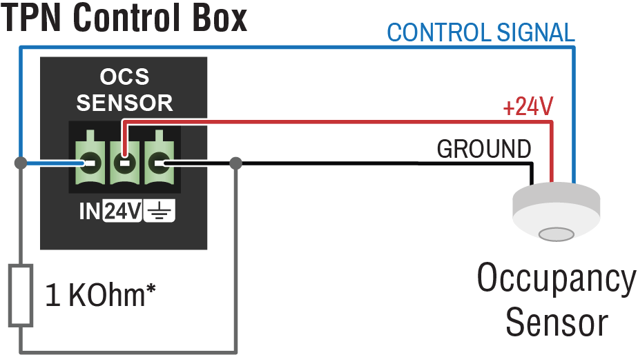
* The extra wire and the resistor are recommended only for 'active high' type sensors.
16.9. Release Notes of the Firmware Packages
16.9.1. Endpoint Firmware Packages
Affected endpoint models:
▪HDMI-TPN-TX107
▪HDMI-TPN-TX107D
▪HDMI-TPN-RX107
▪HDMI-TPN-RX107D
▪HDMI-TPN-TX207AU2K
▪HDMI-TPN-TX207DU2K
▪HDMI-TPN-RX107AU2K
▪HDMI-TPN-RX107A-SR
▪HDMI-TPN-RX107D-SR
▪HDMI-TPN-RX107AU2K-SR
▪HDMI-TPN-RX107DU2K-SR
▪HDMI-OPTN-TX100A
▪HDMI-OPTN-RX100A
▪HDMI-OPTN-RX100A-SR
▪HDMI-OPTN-TX200AU2K
▪HDMI-OPTN-RX100AU2K
▪HDMI-OPTN-RX100AU2K-SR
v2.6.1b1
Release date: 2025-09-15
New feature:
▪From this version on, extenders with Dante audio capabilities are also supported: HDMI-TPN-TX107D, HDMI-TPN-RX107D, HDMI-TPN-RX107D-SR, HDMI-TPN-RX107DU2K-SR, HDMI-TPN-TX207DU2K.
Bugfix:
▪HDMI stream starts with every BlueRiver control server version.
▪TX-RX communication failures are fixed by AVX FW updated to 2.3.0.5
▪AUDIOMUTE LW2 command only accepts valid arguments.
v2.5.2b1
Release date: 2024-11-19
New feature:
▪From this version on, the fiber based scaling receivers (HDMI-OPTN-RX100A-SR and HDMI-OPTN-RX100AU2K-SR) are also supported.
Bugfix:
▪Improved on the quality of the link between the TX and the RX devices. This has a positive effect both on the RS232 and the Ethernet communication.
Known issue:
▪When a scaling receiver is connected to a transmitter in point-to-point mode, the image output may become unstable if, the receiver is in fast switch mode and the embedded audio is set to 192 kHz and 24-bit.
▪Factory resetting the RX device causes the established USB KVM connection not to work anymore. Restarting either the transmitter or the receiver resolves the problem.
v2.5.0b8
Release date: 2024-05-22
New feature:
▪From this version on, the copper based scaling receivers (HDMI-TPN-RX107A-SR and HDMI-TPN-RX107AU2K-SR) are also supported.
▪From this version on, the fiber based extenders (HDMI-OPTN-TX100A, HDMI-OPTN-TX200AU2K, HDMI-OPTN-RX100A, and HDMI-OPTN-RX100AU2K) are also supported.
Bugfix:
▪From this version on, the HDCP is reported as not supported towards a source connected to a TX device when the supported HDCP version of the sink connected to the RX unit cannot be determined.
▪Fixed a bug that caused the video signal on the HDMI output of a receiver device to disappear when the HDMI cable to a sink device is disconnected and connected again.
Known issue:
▪Factory resetting either the TX or the RX device causes the established USB2.0 connection not to work anymore. Unplugging and replugging the corresponding USB device or restarting either the transmitter or the receiver resolves the problem.
v2.4.2b1
Release date: 2023-12-20
Bugfix:
▪Manufacturing support
v2.4.1b1
Release date: 2023-12-15
Bugfix:
▪Fixed a bug that caused some device parameters not to be set to their factory default value after a factory reset.
v2.4.0b4
Release date: 2023-12-12
New feature:
▪From this version on, the product variants with USB2.0 transmission capabilities (HDMI-TPN-TX207AU2K and HDMI-TPN-RX107AU2K) are supported.
Bugfix:
▪Fixed a bug that caused the Ethernet extension through the transmitter-receiver pair to be interrupted when there was a transition between HDMI1.4 and HDMI2.0 video signals on the transmitter input.
▪Fixed a bug that caused a video with color depth of 10 or 12 bit/component to be converted to 8 bit/component.
▪Fixed a bug that caused a 422 10bit input signals to be converted to 422 8bit during transmission.
▪Fixed a bug that caused the de-embedded audio to be muted on the analog audio output when a dispay with DVI EDID is connected to the local output of the transmitter device.
▪Fixed a bug that resulted in muted audio on the analog output after a factory reset (e.g. during firmware upgrade).
Known issue:
▪A clicking sound can be heard in the analog audio output when the audio content in the incoming HDMI stream changes from compressed audio to uncompressed audio or vice versa.
▪After a factory reset not all parameters are set to their factory default value.
v2.1.0b2
Release date: 2023-05-26
Known issue:
▪When the HDMI AUDIO is re-embedded in the output HDMI stream on a HDMI-TPN-RX107 receiver, a switch to a new source with different HDMI AUDIO sampling frequency might result in a flickering of the video content.
▪Currently, only the HF-VSIF is passed through the TPN transmitter and receiver pair. As a result, HDR10 and Dolby Vision is currently not supported.
16.9.2. TPN Control Unit Firmware Packages
Affected model:
▪TPN-CTU-X50
v1.6.0b2
Release date: 2025-07-14
New feature:
▪Major LARA update: LARA 1.3.1 integration. LARA changelog is available on the LARA portal.
▪Remote System Logging functionality is available now under the V1/MANAGEMENT/LOG/REMOTE LW3 path.
▪New Buildroot version: 2025.02.
v1.5.0b5
Release date: 2025-06-17
New feature:
▪Main_2, Main_3, and Main_4 MAC addresses are now automatically generated for every device. These MAC addresses are utilized when multiple VLANs are configured, simplifying network integration.
▪Support Package Enhancement: The AVX settings of SDVoE devices are now included in the support package, facilitating more efficient debugging and issue analysis.
Bugfix:
▪Resolved Issue: A memory leak that was causing long-running devices to freeze has been fixed.
v1.4.0b4
Release date: 2024-12-18
New feature:
▪Major update on LARA is here: LARA 1.3 integration. Detailed LARA change log is available on the LARA portal.
v1.3.0b2
Release date: 2024-11-21
New feature:
▪Added the ability to filter traffic and separate the management network from the AV (default) network. When network separation is enabled, the update of devices on the AV (default) network through LDU are not possible. Please refer to the user manual for further details. Additional setup limitations are also documented in the user manual.
Bugfix:
▪Fixed an issue in the Taurus Webserver where redirects caused confusion in the frontend due to unclear sources.
▪Fixed an issue preventing logs from being saved to permanent storage by updating the logging configuration to ensure proper functionality.
v1.2.0b7
Release date: 2024-07-19
New feature:
▪From this version on, the LARA running on the TPN-CTU-X50 has a TPN driver module that can be used for controlling a TPN system.
▪From this version on, it is possible to enable or disable the control of the Icron USB2.0 devices by the SDVoE Control Server.
▪From this version on, the LARA running on the TPN-CTU-X50 has a driver module that can be used for controlling USB 2.0 (Icron) capable Lightware devices.
▪LARA has been upgraded to v1.2.2.
▪The SDVoE Control Server has been upgraded to v3.7.0.0.
Bugfix:
▪Added the formerly missing buttons to enable the TCI API interface and the SDVoE Control Server to LDC and the embedded graphical user interface.
▪Added the formerly missing Identify me and Dark mode buttons to LDC and the embedded graphical user interface.
v1.0.0b2
Release date: 2024-04-29
Known issue:
▪The Identify me and the Dark mode buttons are missing from the graphical user interface of the TPN-CTU.
▪The TCI API SDVoE interface and the SDVoE Control Server can only be enabled or disabled through LW3 and not through LDC. (The corresponding LW3 properties are /V1/MANAGEMENT/NETWORK/SERVICES/TELNET.Enabled and /V1/MANAGEMENT/NETWORK/SERVICES/BLUERIVER.Enabled, respectively.)
▪The host name is reset to its factory default value upon a power cut off.
16.10. Hashtag Keyword List
This user manual contains keywords with hashtags (#) to help you find the relevant information as quick as possible.
The format of the keywords is the following:
#<keyword>
The usage of the keywords: use the Search function (Ctrl+F / Cmd+F) of your PDF reader application, type the # (hashtag) character and the wished keyword.
The #new special keyword indicates a new feature/function that has just appeared in the latest firmware or software version.
Example
#dhcp
This keyword is placed at the DHCP (dynamic IP address) setting in the front panel operation, the Lightware Device Controller (LDC) and the LW3 programmer's reference section.
The following list contains all hashtag keywords placed in the document with a short description belonging to them. The list is in alphabetical order by the hashtag keywords.
|
Hashtag Keyword |
Description |
|---|---|
|
#8021x |
802.1X configuration |
|
#advancedview |
Advanced view window |
|
#audio |
Audio related settings |
|
#authentication |
Basic authentication settings for CTU |
|
#backup |
Configuration cloning (backup) |
|
#bootload |
Bootload mode setting |
|
#builtinweb |
Built-in web for CTU |
|
#certificate |
Certificate management |
|
#configurationcloning |
Configuration cloning (backup) |
|
#crosspoint |
Crosspoint switch setting |
|
#darkmode |
Dark mode setting |
|
#date |
Date setting in the CTU |
|
#devicelabel |
Device label |
|
#dhcp |
Dynamic IP address (DHCP) setting |
|
#edid |
EDID related settings |
|
#endpointmanagement |
Endpoint management for the CTU |
|
#ethernet |
Ethernet port settings |
|
#factory |
Factory default settings |
|
#firmwareupdate |
Firmware updating |
|
#firmwareversion |
Firmware version query |
|
#gpio |
GPIO related settings |
|
#hdcp |
HDCP-encryption related setting |
|
#health |
System monitoring (health) related information |
|
#hostname |
Host name setting for CTU |
|
#icron |
USB KVM related settings |
|
#identifyme |
Identify me (identify the device) feature |
|
#ipaddress |
IP address related settings |
|
#kvm |
USB KVM related settings |
|
#label |
Device label |
|
#lara |
LARA configuration |
|
#link |
SFP+ link related information |
|
#log |
System log |
|
#mac |
MAC address query |
|
#message |
Message sending via communication ports |
|
#network |
Network (IP address) related settings |
|
#new |
New feature/function of the product |
|
#ntp |
NTP (Network Time Protocol) settings |
|
#ocs |
Occupancy sensor related settings |
|
#pairing |
Icron USB KVM device pairing |
|
#password |
Password setting |
|
#portstatus |
Source/destination port status query |
|
#reboot |
Restarting the device |
|
#restart |
Restarting the device |
|
#rs232 |
RS-232 related settings |
|
#rs-232 |
RS-232 related settings |
|
#scaler |
Scaler related settings |
|
#security |
Basic IT security related settings for CTU |
|
#serial |
RS-232 related settings |
|
#status |
Status query |
|
#switch |
Crosspoint switch setting |
|
#systemmonitor |
System monitoring (health) related information |
|
#terminal |
Advanced view window |
|
#time |
Time setting in the CTU |
|
#update |
Firmware updating |
|
#uplink |
SFP+ link related information |
|
#usbkvm |
USB KVM related settings |
|
#volume |
Volume (for analog audio) setting |
|
#web |
Built-in web for CTU |

16.11. Further Information
Limited Warranty Statement
1. Lightware Visual Engineering PLC (Lightware) warrants to all trade and end user customers that any Lightware product purchased will be free from manufacturing defects in both material and workmanship for three (3) years from purchase unless stated otherwise below. The warranty period will begin on the latest possible date where proof of purchase/delivery can be provided by the customer. In the event that no proof can be provided (empty ‘Date of purchase’ field or a copy of invoice), the warranty period will begin from the point of delivery from Lightware.
1.1. 25G and MODEX product series will be subject to a seven (7) year warranty period under the same terms as outlined in this document.
1.2. If during the first three (3) months of purchase, the customer is unhappy with any aspect of a Lightware product, Lightware will accept a return for full credit.
1.3. Any product that fails in the first six (6) months of the warranty period will automatically be eligible for replacement and advanced replacement where available. Any replacements provided will be warranted for the remainder of the original unit’s warranty period.
1.4. Product failures from six (6) months to the end of the warranty period will either be repaired or replaced at the discretion of Lightware. If Lightware chooses to replace the product, then the replacement will be warranted for the remainder of the original unit’s warranty period.
2. The above-stated warranty and procedures will not apply to any product that has been:
2.1. Modified, repaired or altered by anyone other than a certified Lightware engineer unless expressly agreed beforehand.
2.2. Used in any application other than that for which it was intended.
2.3. Subjected to any mechanical or electrical abuse or accidental damage.
2.4. Any costs incurred for repair/replacement of goods that fall into the above categories (2.1., 2.2., 2.3.) will be borne by the customer at a pre-agreed figure.
3. All products to be returned to Lightware require a return material authorization number (RMA) prior to shipment, and this number must be clearly marked on the box. If an RMA number is not obtained or is not clearly marked on the box, Lightware will refuse the shipment.
3.1. The customer will be responsible for in-bound and Lightware will be responsible for out-bound shipping costs.
3.2. Newly repaired or replaced products will be warranted to the end of the originally purchased product's warranty period.
Document Revision History
|
Rev. |
Release date |
Changes |
Editor |
|
|
19-07-2024 |
Initial version |
Tamas Forgacs |
|
|
|||
|
|
20-06-2025 |
Added Device IP change in CTU during firmware update chapter |
Tamas Forgacs |
|
|
25-09-2025 |
Updates added with important information about default operation of scaling receivers; Major bugfixes |
Tamas Forgacs |


+36 1 255 3810
Lightware Visual Engineering PLC.
Gizella 51-57, Budapest H-1143, Hungary
©2025 Lightware Visual Engineering. All rights reserved. All trademarks mentioned are the property of their respective owners. Specifications subject to change without notice.