
USER MANUAL
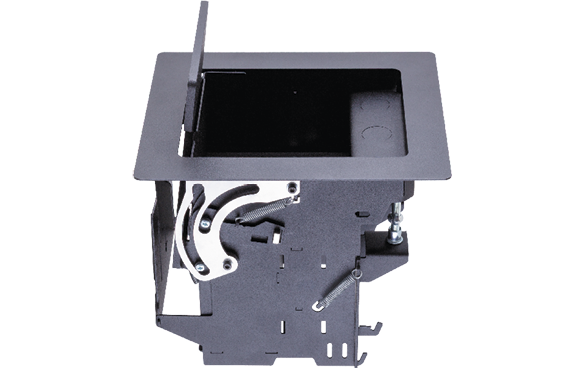
TBX-M210-K
TBX-M220-K
Table Connect Box
|
|
|
|
||
|
|
|
|
||
|
|
||||


Class I apparatus construction.
This equipment must be used with a mains power system with a protective earth connection. The third (earth) pin is a safety feature, do not bypass or disable it. The equipment should be operated only from the power source indicated on the product.
To disconnect the equipment safely from power, remove the power cord from the rear of the equipment or from the power source. The MAINS plug is used as the disconnect device, the disconnect device shall remain readily operable.
There are no user-serviceable parts inside of the unit. Removal of the cover will expose dangerous voltages. To avoid personal injury, do not remove the cover. Do not operate the unit without the cover installed.
The appliance must be safely connected to multimedia systems. Follow instructions described in this manual.

Ventilation
For the correct ventilation and to avoid overheating, ensure enough free space around the appliance. Do not cover the appliance, leave the ventilation holes free and never block or bypass the ventilators (if there are any).
WARNING
To prevent injury, the apparatus is recommended to be securely attached to the floor/wall, or mounted in accordance with the installation instructions. The apparatus shall not be exposed to dripping or splashing, and no objects filled with liquids, such as vases, shall be placed on the apparatus. No naked flame sources, such as lit candles, should be placed on the apparatus.
Replacing the AC fuse (if any)
Unplug the AC power cord from the device. Locate the AC fuse on the rear panel. Replace only the AC fuse as indicated on the rear panel. Connect the power cord to the switcher and to the AC power source. Make sure the switcher is working properly.
Waste Electrical & Electronic Equipment (WEEE)
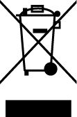
This marking shown on the product or its literature indicates that it should not be disposed with other household wastes at the end of its working life. To prevent possible harm to the environment or human health from uncontrolled waste disposal, please separate this from other types of wastes and recycle it responsibly to promote the sustainable reuse of material resources. Household users should contact either the retailer where they purchased this product or their local government office for details of where and how they can take this item for environmentally safe recycling. Business users should contact their supplier and check the terms and conditions of the purchase contract. This product should not be mixed with other commercial wastes for disposal.
Common Safety Symbols
|
Symbol |
Description |

|
Direct current |
|
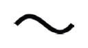
Alternating current |
|
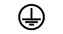
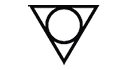
Protective conductor terminal |
|
Equipotential Connector |

|
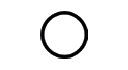
On (Power) |
|
Off (Power) |

|
Double insulation |

|
Caution, possibility of electric shock |

|
Caution |

|
Laser radiation |

|
Warning, Rotating fan |

|
Caution: for indoor use only |
Document Revision History
|
Rev. |
Release date |
Changes |
Editor |
|
v1 |
2026-06-22 |
Initial release. |
Nikolett Keindl |
|
v2 |
2026-09-10 |
ToC correction. |
Laszlo Zsedenyi |
Contact Us
+36 1 255 3800
+36 1 255 3810
Lightware Visual Engineering PLC.
Gizella 51-57, Budapest H-1143, Hungary
©2026 Lightware Visual Engineering. All rights reserved.
All trademarks mentioned are the property of their respective owners.
Specifications are subject to change without notice.
Thank you for choosing Lightware’s TBX Table Connect Box devices. In the first chapter we would like to introduce the device by highlighting the most important features in the sections listed below:
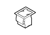
The Table Connect Box is easy to install into a table or desk. It allows convenient access for several AV cables to connect with BYOD sources like laptops. It also has 2 power outlets for chargers or other user equipment.
The user can open the lid and the cables can be pulled out to connect to the device. When not used, the cables can be put back with the help of gravity. The integration is quick and easy with the mounting kit. The video extender can be mounted under the desk and the cables can be connected.
The assembling of certain accessories can be found in the Mounting Options section
|
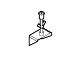
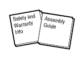
Supplied accessories |
|||||
|
|
|
|
|
|
|
Table Box |
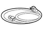
Power cable |
Cable retaining clip |
Mounting ear with fixing screw (2x) |
Safety and Warranty Info, Assembly Guide |
|
|
TBX-M210-K |
|
|
|
|
|
|
TBX-M220-K |
|
|
|
|
|


This chapter is about the physical structure of the device.
The pictured model is TBX-M210-K. The only difference between the models is the type of power outlets.
Top View
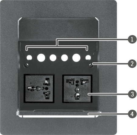
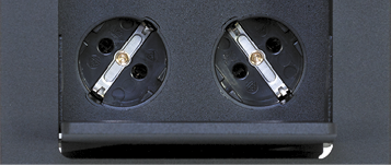
Power outlets in TBX-M220-K
Bottom View
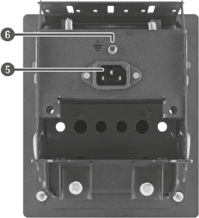
|
|
Cable holes |
Holes with 8, 10 and 12 mm diameter. |
|
|
Service hole |
To access potential fixing screws. |
|
|
Power outlets. |
Standard IEC power connectors. ▪For TBX-M210-K models: 2x multiregion AC connectors. ▪For TBX-M220-K models: 2x European AC socket (Schuko CEE 7/3) |
|
|
Lid |
It can be tilted by the user. |
|
|
AC connector |
Standard C-13 IEC connector accepting 100-240 V, 50 or 60 Hz up to 8A current. |
|
|
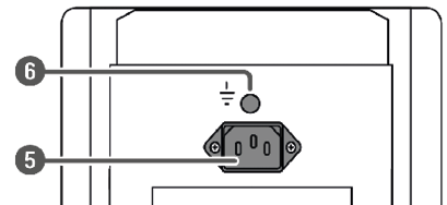
Connector for grounding |
Connect the protective ground connection (recommended). |


WARNING!The power outlets are not suitable for heating appliances or vaccuum cleaners even in case of using for a short period of time.
This chapter is about the installation of the devices and connecting to other appliances, also presenting the mounting options and further assembly steps.
DIFFERENCE:The table box has undergone some changes in autumn 2025. See the Mechanical Drawings section for what changed.
3.1.1. Installation Steps - Newer Model
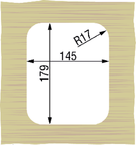
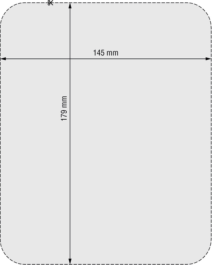
Step 1.Cut the indicated hole in the desk; you can use the cut-out template.
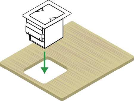
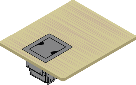
Step 2.Insert the table box into the table
Step 3.Place the fixing ears:
▪Into the upper position for 10-45 mm thick tabletops.
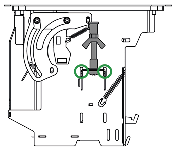
Please pay attention to the direction of the ear; upside down position is not recommended. Fasten the wing-nut (if installed) and the lower screw by a screwdriver or bit tool with PH2 head.
▪Into the lower position for 44-110 mm thick tabletops.
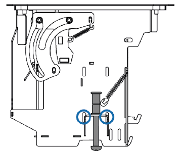
WARNING!The screw must be tightened by hand only. Electric screwdrivers must not be used since an excessive tension will cause permanent deformation.
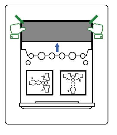
Step 4.Pop out the cover plate with a screwdriver. Find the small hole in the middle along the plate edge and remove the plate.
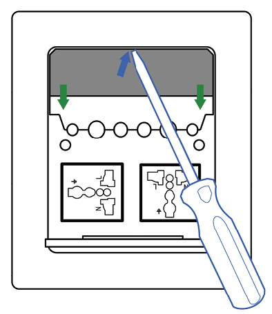
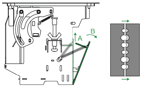
Step 5.Fix the desired cables one-by-one:
▪Open the side plate (Step A and B); it can be fixed in opened position.
▪The upper plates will open up; put the desired cables through the holes.
Step 6.Closing
▪Close the side plate (press up and close).
▪Insert the cover plate; position the bottom, then press the two edges to fix it.
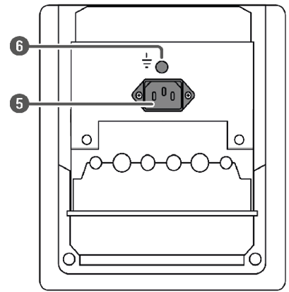
Step 7.Fix the protective ground to the screw bolt (6), nut size: M6. Connect the power cord to the AC inlet (5), then to the power outlet.
Step 8.Ready!
3.1.2. Installation Steps - Older Model
Step 1.Cut the indicated hole in the desk; you can use the Cut-out Template (1:1).
Step 2.Fix the cable tie mount (green-colored, not supplied with the product). Two screw-bolts (claret-colored) are designed for this purpose; use the M4 nuts to fasten (blue-colored). You can uncrew the M4 nuts from the screw-bolt on the left/right side, see fig.A in the next step.
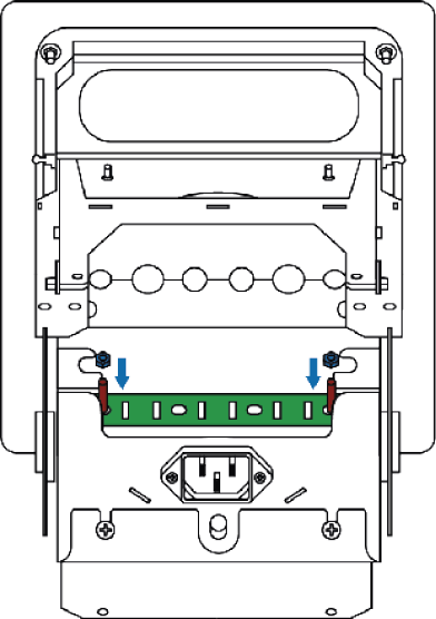
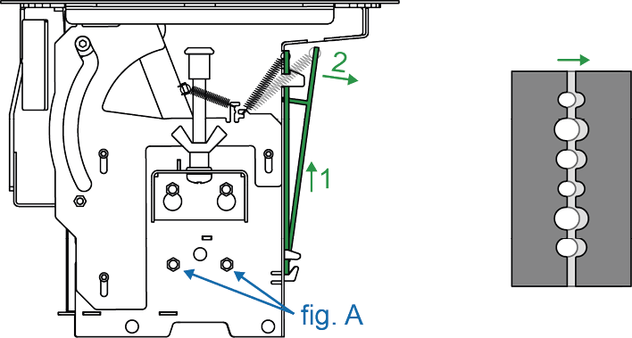
Step 3.Fix the desired cables one-by-one. Put the desired cable through the cut-out hole, open the latch, insert the cable and close the latch. See the opening mechanism in the image:
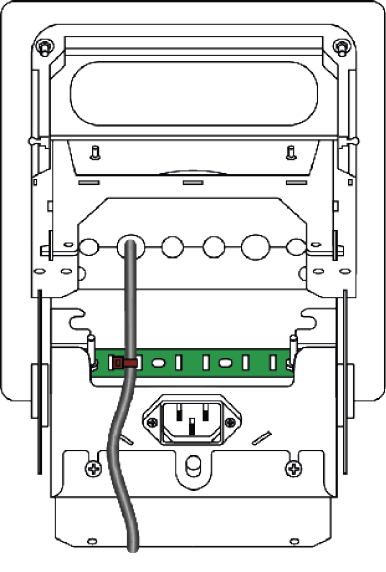
Step 4.Fix the cables to the green-colored cable tie mount..
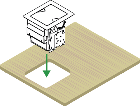
Step 5.Insert the Table Box into the table.
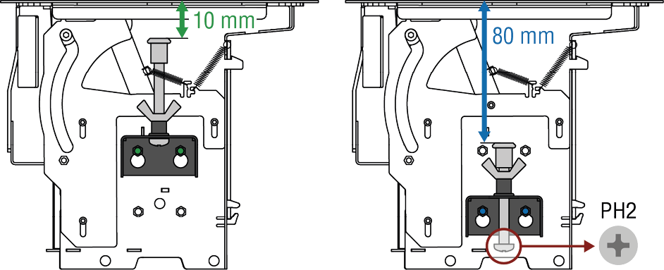
Step 6.Place the fixing ears to the required upper or lower position. Please pay attention to the direction of the ear; upside down position is not recommended. Fasten the screw by a screwdriver or bit tool with PH2 head. If necessary, the hex socket head can be released by a hex key (size 4).
Step 7.Fix the protective ground to the screw bolt (6), nut size: M6. Connect the power cord to the AC inlet (5), then to the power outlet.
Step 8.Ready!
WARNING!Please note that damaged cables must not be used with the Table Box. Likewise, if the power cable of a device is damaged, it must not be plugged into the outlets. Damaged cables in the Table Box shall be replaced as soon as possible.
If any of the cables need to be replaced, the Table Box can be detached from the table as follows:
In case of new models
Step 1.Disconnect the AC power cord from the connector.
Step 2.Pop out the cover plate.
Step 3.Grab the cables and open the latch.
Step 4.Remove the unnecessary cable and insert the new one.
Step 5.Insert the cover plate.
Step 6.Connect the power cord to the connector.
In case of old models
Step 1.Disconnect the AC power cord from the connector.
Step 2.Detach the Table Box from the table.
Step 3.Remove the unnecessary cable and insert the new one.
Step 4.Place the Table Box back into the hole and fix it with the ears.
Step 5.Connect the power cord to the connector.
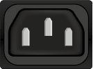
The TBX series table boxes contain a standard IEC power connector that works with 100-240 Volts AC, 50 Hz or 60 Hz power sources.
Connect the power cord to the AC input connector.
3.2.2. Multi-region AC Connector

The TBX-M210-K models offer two multi-region AC connectors for a wide variety of AC plugs. They provide power for laptops or other user equipment.
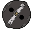
The TBX-M220-K models offer two CEE 7/3 (Schuko) type European AC sockets to provide power for laptops or other user equipment.
Tables, drawings, guides, and technical details as follows:
INFO:Specifications are subject to change without notice.
General
|
Compliance |
CE, UKCA |
|
Electrical safety |
EN 62368-1:2020 |
|
RoHS |
EN 63000:2018 |
|
Warranty |
3 years |
|
Operating temperature |
0° to +50˚C (+32° to +122˚F) |
|
Operating humidity |
10% to 90%, non-condensing |
|
Cooling |
Passive |
Power
|
Power outlet (TBX-M210-K) |
2x multi-region AC connectors |
|
Power outlet (TBX-M220-K) |
2x European AC connectors (Schuko CEE 7/3) |
|
Power input connector |
IEC connector |
|
Power input |
100-240 V, 50/60 Hz |
|
Max. load (current) |
8A |
Enclosure
|
Device dimensions (in mm) |
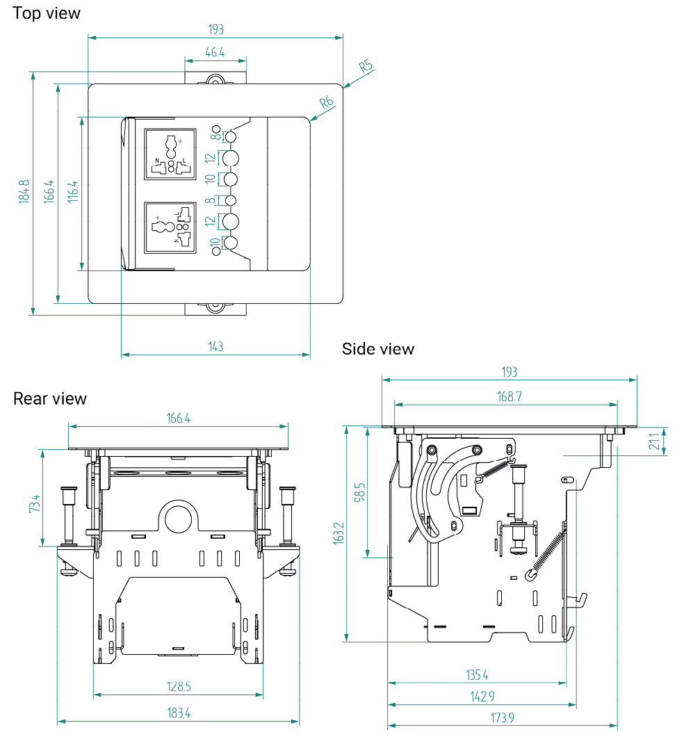
193 L x 184.8 W x 163.2 H |
|
Device dimensions (in inch) |
7.6 L x 7.27 W x 6.42 H |
|
Weight |
2540 g (5.6 lb) |
|
Desk cutout hole (in mm) |
145 W x 179 L |
|
Desk cutout hole (in inch) |
5.7 W x 7.04 L |
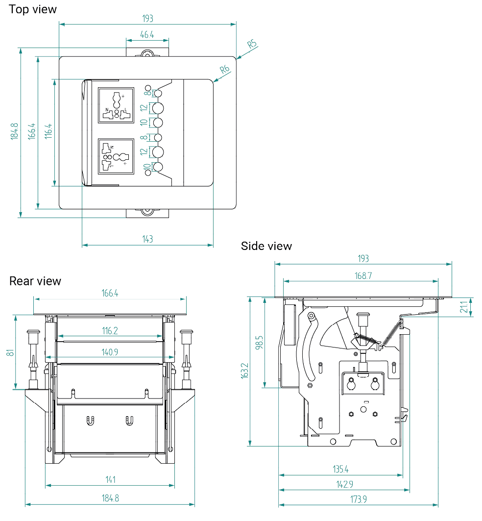
TBX-M210-K can be seen in the drawings, but the dimensions are the same in both models.
INFO:Dimensions are in mm.
Old Model
The Table Box has undergone some changes in autumn 2025. Here you can see the previous model.
4.4. Further Document Information
Symbol Legend
The following symbols and markings are used in the document:
WARNING!Safety-related information that is highly recommended to read and keep in every case!
ATTENTION!Useful information for performing a successful procedure; it is recommended to read.
DIFFERENCE:Feature or function that is available with a specific firmware/hardware version or product variant.
INFO:A notice, which contains additional information. Procedure can be successful without reading it.
DEFINITION:The short description of a feature or a function.
TIPS AND TRICKS:Ideas that you may have not known yet, but can be useful.
Navigation Buttons
|
Buttons in the PDF version |
Buttons in the HTML version |
|||
|
|
Navigate to the Table of Contents. |
|
Open the main Table of Contents. |
|
|
|
Go back to the previous page. If you clicked on a link previously, you can go back to the source page by pressing the button. |
|
Navigate to the Online User Manuals webpage. |
|
|
|
Navigate to the Bookmark page. |
|
Navigate to the Bookmark page in this User Manual. |
|
|
|
Visit www.lightware.com. |
|
Download the PDF version of the User Manual. |
|


About Printing
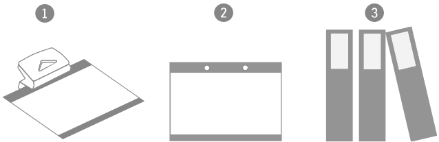
Lightware Visual Engineering supports green technologies and eco-friendly mentality. Thus, this document is made primarily for digital usage. If you need to print out a few pages for any reason, follow the recommended printing settings:
▪Page size: A4
▪Output size: Fit to page or Match page size
▪Orientation: Landscape
TIPS AND TRICKS: Thanks to the size of the original page, a border around the content (gray on the second picture below) makes it possible to organize the pages better. After punching holes in the printed pages, they can easily be placed into a ring folder.
4.5. Limited Warranty Statement
1. Lightware Visual Engineering PLC (Lightware) warrants to all trade and end user customers that any Lightware product purchased will be free from manufacturing defects in both material and workmanship for three (3) years from purchase unless stated otherwise below. The warranty period will begin on the latest possible date where proof of purchase/delivery can be provided by the customer. In the event that no proof can be provided (empty ‘Date of purchase’ field or a copy of invoice), the warranty period will begin from the point of delivery from Lightware.
1.1. 25G and MODEX product series will be subject to a seven (7) year warranty period under the same terms as outlined in this document.
1.2. If during the first three (3) months of purchase, the customer is unhappy with any aspect of a Lightware product, Lightware will accept a return for full credit.
1.3. Any product that fails in the first six (6) months of the warranty period will automatically be eligible for replacement and advanced replacement where available. Any replacements provided will be warranted for the remainder of the original unit’s warranty period.
1.4. Product failures from six (6) months to the end of the warranty period will either be repaired or replaced at the discretion of Lightware. If Lightware chooses to replace the product, then the replacement will be warranted for the remainder of the original unit’s warranty period.
2. The above-stated warranty and procedures will not apply to any product that has been:
2.1. Modified, repaired or altered by anyone other than a certified Lightware engineer unless expressly agreed beforehand.
2.2. Used in any application other than that for which it was intended.
2.3. Subjected to any mechanical or electrical abuse or accidental damage.
2.4. Any costs incurred for repair/replacement of goods that fall into the categories above (2.1., 2.2., 2.3.) will be borne by the customer at a pre-agreed figure.
3. All products to be returned to Lightware require a return material authorization number (RMA) prior to shipment, and this number must be clearly marked on the box. If an RMA number is not obtained or is not clearly marked on the box, Lightware will refuse the shipment.
3.1. The customer will be responsible for in-bound, and Lightware will be responsible for out-bound shipping costs.
3.2. Newly repaired or replaced products will be warranted to the end of the originally purchased product's warranty period.