
USER MANUAL
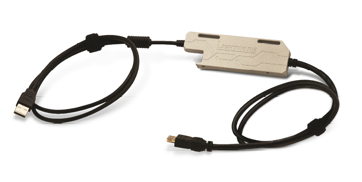
HDMI20-OPTJ-RX90
HDMI20-OPTJ-TX90
OPTJ Power tray SC
OPTJ Power tray NTD
OPTJ Power tray NTQ
Multimode Fiber Optical Multimedia Extender
|
|
|
|
||
|
|
|
|
||
|
|
|
|
||


|
|
||||

Class II apparatus construction.
The equipment should be operated only from the power source indicated on the product.
To disconnect the equipment safely from power, remove the power cord from the rear of the equipment, or from the power source. The MAINS plug is used as the disconnect device, the disconnect device shall remain readily operable.
There are no user-serviceable parts inside of the unit. Removal of the cover will expose dangerous voltages. To avoid personal injury, do not remove the cover. Do not operate the unit without the cover installed.
The appliance must be safely connected to multimedia systems. Follow instructions described in this manual.

WARNING
To prevent injury, the apparatus is recommended to be securely attached to the floor/wall, or mounted in accordance with the installation instructions. The apparatus shall not be exposed to dripping or splashing, and no objects filled with liquids, such as vases, shall be placed on the apparatus. No naked flame sources, such as lit candles, should be placed on the apparatus.
Waste Electrical & Electronic Equipment (WEEE)

This marking shown on the product or its literature indicates that it should not be disposed with other household wastes at the end of its working life. To prevent possible harm to the environment or human health from uncontrolled waste disposal, please separate this from other types of wastes and recycle it responsibly to promote the sustainable reuse of material resources. Household users should contact either the retailer where they purchased this product or their local government office for details of where and how they can take this item for environmentally safe recycling. Business users should contact their supplier and check the terms and conditions of the purchase contract. This product should not be mixed with other commercial wastes for disposal.
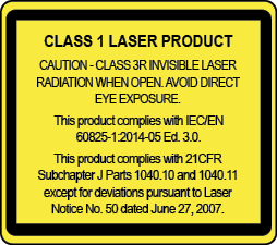
Caution: Laser product

Common Safety Symbols
|
Symbol |
Description |

|
Direct current |

|
Alternating current |

|
Protective conductor terminal |

|
Equipotential Connector |

|
On (Power) |

|
Off (Power) |

|
Double insulation |

|
Caution, possibility of eletric shock |

|
Caution |

|
Laser radiation |

|
Warning, Rotating fan |

|
Caution: for indoor use only |
Document Revision History
|
Rev. |
Release date |
Changes |
Editor |
|
v1 |
2026-05-12 |
Initial release |
Tamas Forgacs |
|
v2 |
2026-06-22 |
OPTJ power tray devices added. |
Nikolett Keindl |
|
v3 |
2026-08-31 |
ToC correction. |
Laszlo Zsedenyi |
Contact Us
+36 1 255 3800
+36 1 255 3810
Lightware Visual Engineering PLC.
Gizella 51-57, Budapest H-1143, Hungary
©2026 Lightware Visual Engineering. All rights reserved.
All trademarks mentioned are the property of their respective owners.
Specifications are subject to change without notice.
Thank you for choosing Lightware’s HDMI20-OPTJ-90 series devices. In the first chapter we would like to introduce the device by highlighting the most important features in the sections listed below:
Thank you for choosing Lightware HDMI20-OPTJ-TX90 and RX90 multimedia extenders. The HDMI20-OPTJ-TX90 and HDMI20-OPTJ-RX90 are HDMI 2.0 compatible fiber optical extenders provide uncompressed signal extension with embedded audio to a range of 700 m over a single multimode fiber cable connection. Its rugged, solid metal casing provides excellent cooling and maximum reliability.
About the Power tray
The Power tray is a 1RU-size housing accessory that can enclose up to 16 HDMI20-OPTJ-TX/RX90 units, while also providing power for every installed device. The optical fibers are connected to the eight SC duplex or four Neutrik opticalCON QUAD or four Neutrik opticalCON DUO connectors, each carrying four signal fibers from four of the extenders. The HDMI tail cables of the extenders are accessible directly at the back of the Power tray.
About the Serial Number
Lightware devices contain a label indicating the unique serial number of the product. The structure is the following:
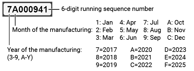
From 1st of October 2024, serial number format of Lightware devices is the following: the first two digits are of the year of manufacture, while the remaining digits make up the running sequence number.

Compatible Products
The TX and RX devices are only compatible with each other.
The assembling of certain accessories can be found in the Mounting Options section. Optional accessories can be purchased separately, please contact sales@lightware.com.
|
Supplied device |
Supplied accessories |
||||||

|
|
|
|

|

|
|
|
|
Transmitter/ receiver module |
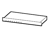
OPTJ Power tray series device |
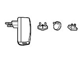
5V DC power adaptor with interchangeable plugs |
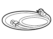
IEC power cable |
Safety & Warranty Info; Quick Start Guide |
M3x6mm screw and toothed foot washer (16x) |
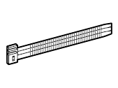
Cable tie (16x) |
|
|
HDMI20-OPTJ-RX90 |
|
- |
|
- |
|
- |
- |
|
HDMI20-OPTJ-TX90 |
|
- |
|
- |
|
- |
- |
|
OPTJ Power tray SC |
- |
|
- |
|
|
|
|
|
OPTJ Power tray NTD |
- |
|
- |
|
|
|
|
|
OPTJ Power tray NTQ |
- |
|
- |
|
|
|
|

1.3. Model Comparison (OPTJ Power Tray Series)
|
Model |
Optical connector |
Number of installable OPTJ extenders |
|
OPTJ Power tray SC |
SC duplex (8x) |
up to 16 |
|
OPTJ Power tray NTQ |
Neutrik NO4FDW-A (4x) |
up to 16 |
|
OPTJ Power tray NTD |
Neutrik NO2-4FDW-A (4x) |
up to 8 |

|
3D and 4K Support |
|
High bandwidth allows extension of resolutions up to 4K and even 3D sources and displays are supported. |
|

|
Signal Transmission up to 700m |
|
Video and audio signal transmission over a single multimode fiber optical cable. |
|

|
Consumer Electronics Control (CEC) |
|
Supports transparent transmitting standard CEC commands in order to remote control the source or sink device. |
|

|
Deep Color Support |
|
It is possible to transmit the highest quality 36-bit video streams and HDR contents for the perfect color reproduction. |
|

|
Wide Range of Audio Format Support |
|
Extenders support the most of known audio signal formats, including HBR audio like Dolby TrueHD and DTS-HD Master Audio 7.1. |
|

|
HDCP 2.2 compliant |
|
The extender fulfills the HDCP 2.2 standard. HDCP capability on the digital video inputs can be disabled when non-protected content is extended. |
|

|
No signal latency |
|
The signal management architecture ensures that there is no delay added between the input and the output. |
|

|
Maximum AV Compatibility |
|
The extender is compatible with HDMI 2.0 standard, as well as with HDMI 1.x and DVI 1.0 standards. |
|

|
Mounting Threads |
|
Mounting threads for the extenders to conform strict installation safety regulations. |

16 pcs extenders mounted in a OPTJ Power tray and connected to a MX2-8x8-HDMI20-Audio-L matrix switcher
The following sections are about the physical structure of the device, input/ output ports and connectors; software and hardware capabilities:
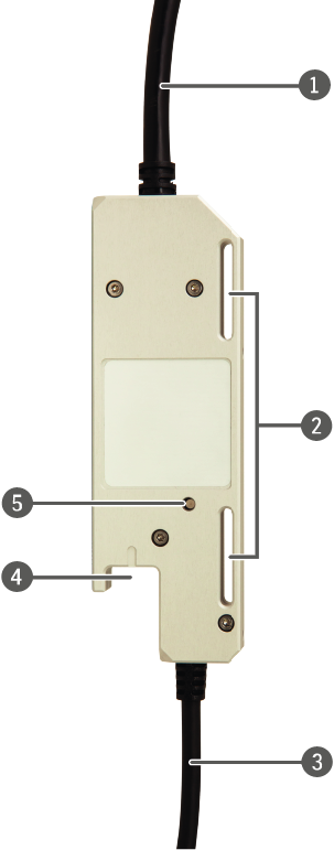
|
|
HDMI plug |
HDMI connector plug for HDMI audio and video signal transmission. The following protocols and features are supported: ▪HDMI 1.x and HDMI 2.0 audio/video - the module automatically selects between HDMI 2.0 and HDMI 1.x based on the type of the signal source or sink device. ▪HDCP 1.4 or HDCP 2.2 encryption - the module automatically selects between HDCP 1.4 and HDCP 2.2 based on the type of the signal source or sink device. ▪EDID, CEC, and HDCP transparent. |
||
|
|
Loopholes |
Loopholes for self-fastening belts for mounting. See the details in the Mounting Options section. |
||
|
|
USB-A plug |
Standard USB-A plug to USB-compatible (1.1 or higher) host port. The following features are supported: ▪The receiver and transmitter can be fully powered from the USB port. This capability is available even if the attached USB host port is “power only”. ▪For transmitter only: USB power is fully compatible with HDMI power. The transmitter performance will not degrade if the HDMI power and USB power are available simultaneously. Similarly, connecting USB power and HDMI power simultaneously will not cause any damage to the attached USB host or HDMI video source. |
||
|
|
SC fiber connector |
SC fiber optical connector. Connect a multimode fiber optical cable between the transmitter and the receiver. The following features are supported: ▪All communication, including audio and video transmission, and HDCP over one optical fiber. ▪The connector supports open fiber detection with high speed laser shutdown. |
||
|
|
Indicates the current status of the transmitted or received optical and HDMI signals, and the HDCP-encryption. |
|||

|
OFF |
Module is not powered. |
||

|
BLINKING (red) |
No fiber link is detected. |
||

|
BLINKING (yellow) |
Fiber link is established, but no HDMI cable is detected (5V is not detected on the source or hotplug is not detected on the sink). |
||

|
ON (yellow) |
Fiber link is established, cable is connected, but no HDMI signal. |
||

|
BLINKING (green) |
Fiber link is established, signal is not HDCP-encrypted. |
||

|
ON (green) |
Fiber link is established, signal is encrypted with HDCP 1.4. |
||

|
BLINKING (blue) |
Fiber link is established, HDCP 2.2 initialization is in progress. |
||

|
ON (blue) |
Fiber link is established, signal is encrypted with HDCP 2.2. |
||
|
Troubleshooting |
||||
|
The following LED statuses mean incorrect extender modes. These can happen when the USB-A plug of the extender is connected to a USB connector where the data transmission is enabled. Solution: Use the supplied power adaptors. |
||||

|
BLINKING (pink) |
The device is in bootloader mode. |
||

|
ON (pink) |
The device is in bootloader mode and bootloader is configured by the USB host. |
||


2.2. Power Tray - Front/Rear View
Front View

Rear View

INFO:The OPTJ Power tray NTQ model can be seen in the rear view picture, but the layout is the same for all three models.
|
|
Status LED indicators of the OPTJ extenders |
The status LED indicators give immediate feedback about the recent status of the HDMI20-OPTJ-TX/RX90 extenders. |
|
|
Power LED |
The Power LED lights green when the unit is powered on. |
|
|
AC connector |
Standard IEC power connector. Accepts 100 to 240 Volts, 50 or 60 Hz power sources. |
|
|
Fiber optical connectors (varied by model) |
▪SC model: 8x SC duplex fiber optical connectors for 16x multimode SC fiber optical cables. ▪NTD model: 4x Neutrik NO2-4FDW-A connectors for 4x Neutrik opticalCON DUO series cables or 8x LC fiber optical cables. ▪NTQ model: 4x Neutrik NO4FDW-A connectors for 4x Neutrik opticalCON QUAD series cables. |
|
|
Mounting slots for the OPTJ extenders |
16x mounting slots for the HDMI20-OPTJ-TX/RX90 extenders. |
This chapter is about the installation of the device and connecting to other appliances, also presenting the mounting options and further assembly steps:
The ergonomic enclosure provides two possible methods for mounting the device.
3.1.1. Option 1 - Mounting the Device to a Rack Shelf
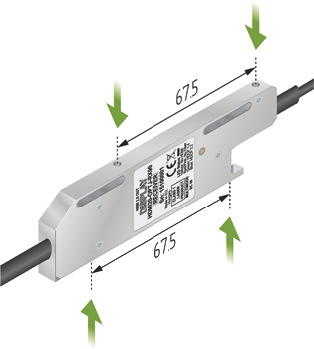
The transmitter and the receiver modules have two mounting holes each with inner threads on the two narrow sides. The distance between the holes is 67,5 mm.
Fasten the device by the screws packaged with the following, compatible mounting accessories:
▪Under-desk mounting kit
▪Under-desk double mounting kit
▪1U high rack shelf
The required screw type: PZ flat head (M3x6mm)
INFO:To order mounting accessories, please contact sales@lightware.com.
3.1.2. Option 2 - Mounting the Device Using Self-Fastener

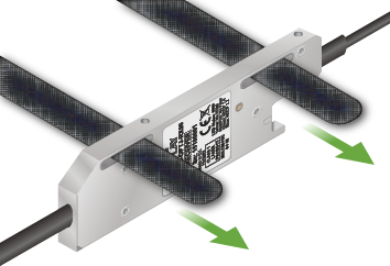
Use the two tie-down loops of the enclosure to thread through the self-fastener. The modules can be mounted to basically any installation point, for example rack frames.
WARNING!In case of installation to a truss, always fix the module with a safety wire as well.
3.1.3. Mounting the Device to the OPTJ Power Tray
The OPTJ Power tray is a 1RU size housing accessory, which can enclose up to 16 pcs of HDMI20-OPTJ-TX/RX90 units, while also providing power source for every installed device.
Three different models are available:
▪SC model: built with 8x SC duplex fiber optical connectors for 16x multimode SC fiber optical cables.
▪NTD model: 4x Neutrik NO2-4FDW-A connectors for 4x Neutrik opticalCON DUO series cables or 8x LC fiber optical cables.
▪NTQ model: 4x Neutrik NO4FDW-A connectors for 4x Neutrik opticalCON QUAD series cables.
INFO:To order mounting accessories, please contact sales@lightware.com.

3.1.4. Mounting the Power Tray
The rack ears allow mounting the device as a standard rack unit installation.
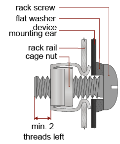

ATTENTION!Always use all four screws to fix the device ears to the rack rail. Choose properly sized screws for mounting. Keep a minimum of two threads left after the nut screw.
INFO:The device is rack-size width and 1U high.
3.1.5. Assembly Steps of Mounting the Extenders to the Power Tray
The following assembly guide is to help to correctly install the HDMI20-OPTJ-TX/RX90 extenders to the Power tray step by step.
Step 1.Remove the small cover
Remove the optical cables from the cable clamps located on the small cover. Remove the 8 screws with a PH1 screwdriver from the locations highlighted with green arrows and remove the small cover plate (gray colored).
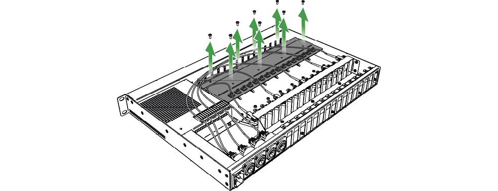
Step 2.Install the OPTJ extenders
Insert each HDMI20-OPTJ-TX/RX90 extender to the mounting slot. Pull the HDMI tail cable across the rear side mounting holes of the Power tray. Fasten the extenders with the provided M3x6 screws and the toothed foot washers (2 screws and 2 washers per extender on the top).
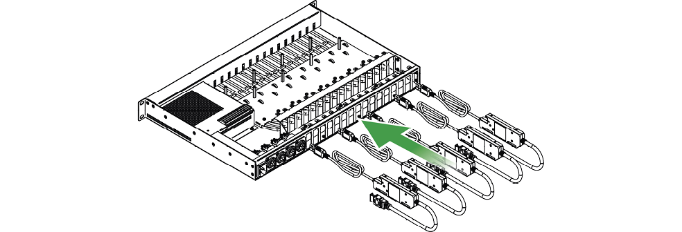
Step 3.Connect the USB cables
Connect the USB-A cables of the extenders to the USB-A connectors of the Power tray (gray colored). Fasten the USB cables with the provided cable ties.
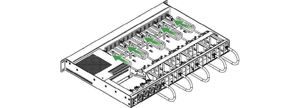
INFO:The USB-A connectors of the Power tray are for powering purpose only. No data transmission is available through them.
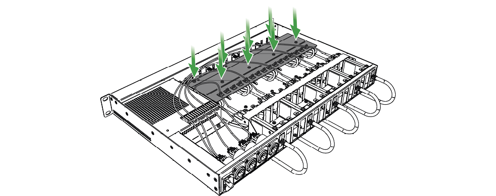
Step 4.Re-insert the small plate
Insert the small cover plate (gray colored) again, and fasten the 8 screws with a PH1 screwdriver.
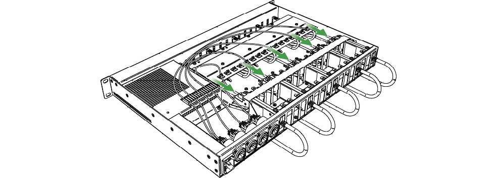
Step 5.Connect the SC fiber cables
Remove the protective caps and connect the SC fiber optical cables to the extenders and insert the optical cables into the cable clamps.
3.1.6. Installation of the OPTJ Extenders into OPTJ Power Tray NTD
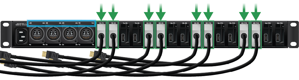
The OPTJ Power tray NTD model is built with four Neutrik opticalCON DUO connectrors that can extend up to eight optical signals.
ATTENTION!The OPTJ Power tray NTD model can handle up to 8 HDMI-OPTJ-TX/RX90 extenders.
The mounting slots (highlighted with green) and the Neutrik opticalCON DUO connectors (highlighted with blue) are labeled with the same ID for easy identification. Thus, the installation of the extenders is recommended into the following slots in the NTD model:
|
Mounting slots |
||||||||||||||||
|
1A (1) |
1B (2) |
1a (3) |
1b (4) |
2A (5) |
2B (6) |
2a (7) |
2b (8) |
3A (9) |
3B (10) |
3a (11) |
3b (12) |
4A (13) |
4B (14) |
4a (15) |
4b (16) |
|
|
Extender installation |
|
|
|
|
|
|
|
|
|
|
|
|
|
|
|
|


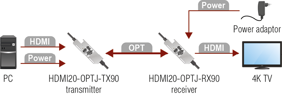

|
Connect the multimode fiber optical cable to the SC fiber connector of the receiver. |

|
Connect the HDMI plug of the receiver to the input port of the sink device (e.g. 4K TV). The extender reads the EDID from the display (projector, monitor, etc), and outputs the video signal according to the set resolution. |

|
Power on the receiver by choosing one of the powering options below: ▪Connect the USB plug of the receiver to the power adaptor. ▪Connect the USB plug of the receiver to the USB connector of the sink device. |
|
|
Connect the multimode fiber optical cable to the SC fiber connector of the transmitter. |

|
Connect the HDMI plug of the transmitter to the output port of the source device (e.g. PC). |

|
Finally power on the transmitter by choosing one of the powering options below: ▪Connect the USB plug of the transmitter to the power adaptor. ▪Connect the USB plug of the transmitter to the USB connector of the source device. ▪Connect the HDMI plug of the transmitter to the output port of the source device (e.g. PC). If the HDMI source device is able to provide enough 5V DC current (500mA), there is no need for external 5V DC power. The extender is powered immediately when the source device is switched on. |

|
Check the Status LED. When the connection is successful, the LEDs on the transmitter and receiver will appear green or blue depending on the HDCP-encryption. |
The following sections contain descriptions and useful technical information on how the devices work in the background. The content is based on experiences and cases we met in practice. These sections help to understand features and technical standards like the following:
Lightware Visual Engineering is a legal HDCP adopter. Several functions have been developed, which helps to solve HDCP related problems. Complex AV systems often have both HDCP and non-HDCP components. The matrix allows transmitting HDCP encrypted and unencrypted signals. The devices will be still HDCP compliant, as they will never output an encrypted signal to a non-HDCP compliant display device. If an encrypted signal is switched to a non-compliant output, a red screen alert or muted screen will appear.
4.1.1. Protected and Unprotected Content
Many video sources send HDCP protected signal if they detect that the sink is HDCP capable – even if the content is not copyrighted. This can cause trouble if an HDCP capable device is connected between the source and the display. In this case, the content cannot be viewed on non-HDCP capable displays and interfaces like event controllers. Rental and staging technicians often complain about certain laptops, which are always sending HDCP encrypted signals if the receiver device (display, matrix router, etc.) reports HDCP compliancy. Even though HDCP encryption is not required all the time (e.g. computer desktop image), certain laptops still do that.
To avoid unnecessary HDCP encryption, Lightware introduced the HDCP enabling/disabling function: the HDCP capability can be disabled in the Lightware device. If HDCP is disabled, the connected source will detect that the sink is not HDCP capable, and turn off authentication.
4.1.2. Disable Unnecessary Encryption
HDCP Compliant Sink
All the devices are HDCP-compliant, no manual setting is required, both protected and unprotected contents are transmitted and displayed on the sink.

Not HDCP-compliant Sink 1.
Not-HDCP compliant sink is connected to the matrix. Some sources (e.g. computers) always send HDCP encrypted signals if the receiver device reports HDCP compliancy, however, HDCP encryption is not required all the time (e.g. computer desktop image). If HDCP is enabled in the matrix, the image will not be displayed on the sink.
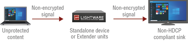
Setting the HDCP parameter to Auto on the output port and disable HDCP on the input port, the transmitted signal will not be encrypted if the content is not protected. Thus, non-HDCP compliant sinks will display non-encrypted signal.
Not HDCP-compliant Sink 2.
The layout is the same as in the previous case: non-HDCP compliant display device is connected to the matrix but the source would send protected content with encryption. If HDCP is enabled on the input port of the matrix, the source will send encrypted signal.
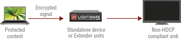
The sink is not HDCP compliant, thus it will not display the video signal, but blank screen is shown. If HDCP is disabled on the input port of the matrix, the source will not send the signal. The solution is to replace the display device with an HDCP-capable one.
HDCP 2.2 is the latest evolution of copy protection. It is designed to create a secure connection between a source and a display. The 2.x version of HDCP is not a continuation of HDCPv1, and is rather a completely different link protection. One of the main differences is the number of the allowed devices within a closed AV system: HDCP 2.2 allows 32 devices (HDCP 1.4 allows 128 devices). A further limit is that up to four level is allowed, which means the protected signal can be transmitted over at most four repeater/matrix/switcher devices. HDCP content protection is activated only if an active video stream is transmitted from the source to the display. The encryption is not activated without a video signal.
HDCP 2.2 standard allows the application of a previous version of HDCP (e.g. HDCP 1.4) between the source and the display if the source device allows it. According to the standard, if the image content is protected with HDCP, the highest supported content protection level has to be applied. However, if the highest level of protection is not justified by the source content, the level may be decreased to avoid compatibility problems; this case is determined by the source.
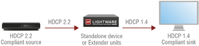
HDCP 2.2 Source and HDCP 1.4 Sink
In this case the signal of an HDCP 2.2 compliant source is switched to an HDCP 1.4 compliant sink device. The signal is encrypted with HDCP 2.2 on the input and encrypted with HDCP 1.4 on the output of the Lightware device. A lower level of encryption may be applied only if the source device/content allows it - according to the HDCP standard. In this case, the HDCP setting on the input port has to be set to HDCP 1.4 and Depends on input on the output port.
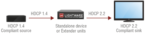
HDCP 1.4 Source and HDCP 2.2 Sink
The example below is the reversal of the previous case. An HDCP 1.4 compliant source sends a signal with HDCP 1.4 encryption. The signal is switched to an HDCP v2.2 compliant sink device. In this case, the outgoing signal has to be encrypted with the highest supported encryption level towards the sink, as the Lightware device and the sink are both HDCP 2.2 compliant. The HDCP 2.2 standard does not allow keeping the original HDCP 1.4 encryption level on the output.
What Kind of Signal Will be on the Output of the Lightware Device?
See the table below that summarizes the possible cases:
|
Incoming Signal |
HDCP 1.4 Compatible Sink |
HDCP 2.2. Compatible Sink |
|---|---|---|
|
HDCP 1.4 |
HDCP 1.4 |
HDCP 2.2 |
|
HDCP 2.2 (convertable)* |
HDCP 1.4 |
HDCP 2.2 |
|
HDCP 2.2 (not convertable)** |
Red screen |
HDCP 2.2 |
* Stream type 0: the video stream allows the conversion of the signal to apply a lower level of encryption.
** Stream type 1: the video stream does not allow the conversion of the signal.
Tables, drawings, guides, technical details and the hashtag keyword list as follows:
INFO:Specifications are subject to change without notice.
5.1.1. HDMI-OPTJ-TX90, HDMI-OPTJ-RX90
General
|
Compliance |
CE, UKCA |
|
EMC (emission) |
EN 55032:2015+A1:2020 |
|
EMC (immunity) |
EN 55035:2017+A11:2020 |
|
RoHS |
EN 63000:2018 |
|
Electrical safety |
EN 62368-1:2024 |
|
Laser safety (Class 1) |
EN 60825-1:2024+A11:2021 |
|
Warranty |
3 years |
|
Cooling |
Passive |
|
Operating temperature |
0 to +50˚C (+32 to +122˚F) |
|
Storage temperature |
-40° to +85˚C (-40° to +185˚F) |
|
Operating humidity |
10% to 90%, non-condensing |
|
Power supply options - TX |
External power adaptor / USB / HDMI |
|
Power supply options - RX |
External power adaptor / USB |
|
Power adaptor |
In 100-240 V AC 50/60 Hz, Out 5V DC, 1 A |
|
Power connector |
USB-A plug |
|
Power consumption - TX (1080p60 / 4K60) |
1.5 W / 2 W |
|
Heat dissipation - TX (1080p60 / 4K60) |
5.12 BTU/h / 6.82 BTU/h |
|
Power consumption - RX (1080p60 / 4K60) |
0.8 W / 1 W |
|
Heat dissipation - RX (1080p60 / 4K60) |
2.73 BTU/h / 3.41 BTU/h |
Enclosure
|
Rack mountable |
Yes, with mounting accessories, check the Mounting Options section |
|
Enclosure material |
Aluminum |
|
Dimensions in mm |
110.5 W x 35.5 D x 11.4 H |
|
Dimensions in inch |
4.35 W x 1.40 D x 0.44 H |
|
Weight (TX) |
145 g (0.32 lbs) |
|
Length of pigtail HDMI cable |
800 mm (31.5 inch) |
|
Length of pigtail USB cable |
1000 mm (39.4 inch) |
Video Port
HDMI Input/Output Port
|
Connector type |
19-pole HDMI Type A plug |
|
Standard |
DVI 1.0, HDMI 1.4, HDMI 2.0 |
|
Color space |
RGB, YCbCr 4:4:4, YCbCr 4:2:2, YCbCr 4:2:0 |
|
Supported resolutions at 8 bits/color * |
up to 4096x2160@60Hz (4:4:4) or up to 3840x2160@60Hz (4:4:4) |
|
Audio formats |
8 channel PCM Dolby Digital, Dolby Digital Plus, Dolby TrueHD, Dolby Atmos DTS, DTS-HD Master Audio 7.1, WMA Pro |
|
HDCP compliancy |
HDCP 1.4 and HDCP 2.2 |
Fiber Optical Port
|
Connector type |
SC simplex receptacle |
|
Laser wavelengths |
High speed lane: 780, 800, 825, 850 nm Low speed lane: 910, 980 nm |
|
Laser class specification |
Class 1 (if enclosure removed: Class 3R) |
|
Compliance |
EN 60825-1:2014+A11:2021 21CFR Subchapter J Parts 1040.40 and 1040.11 except for deviations pursuant to Laser Notice No. 50 dated June 27, 2007 |
|
Output OMA |
-6 dBm |
|
OMA sensitivity |
-12.5 dBm |
General
|
Compliance |
CE, UKCA |
|
EMC (emission) |
EN 55032:2015+A1:2020 |
|
EMC (immunity) |
EN 55035:2017+A11:2020 |
|
RoHS |
EN 63000:2018 |
|
Electrical safety |
EN 62368-1:2024 |
|
Laser safety (Class 1 - if extenders installed) |
EN 60825-1:2024+A11:2021 |
|
Warranty |
3 years |
|
Operating temperature |
0 to +50˚C (+32 to +122˚F) |
|
Operating humidity |
10% to 90%, non-condensing |
|
Cooling |
Passive |
|
Protection against |
Short circuit / Overload |
Power
|
Power supply |
Internal |
|
Power source |
100-240 V AC; 50/60 Hz |
|
Power consumption (loaded with 16 extenders) |
23.7 W |
Enclosure
|
Rack mountable |
Yes |
|
Enclosure material |
1 mm steel |
|
Dimensions in mm |
482.6 W x 300 D x 44.2 H |
|
Dimensions in inch |
19 W x 11.8 D x 1.7 H |
|
Net Weight |
4.13 kg (9.1 lbs) |
Optical Connectors - OPTJ Power Tray SC
|
Connector type |
SC duplex receptacle |
|
Number of connectors |
8 |
Optical Connectors - OPTJ Power Tray NTD
|
Connector type |
Neutrik NO2-4FWD-A receptacle |
|
Number of connectors |
4 |
Optical Connectors - OPTJ Power Tray NTQ
|
Connector type |
Neutrik NO4FWD-A receptacle |
|
Number of connectors |
4 |
USB Connectors
|
Connector type |
USB Type A receptacle |
|
Number of connectors |
16 |
|
DC output voltage |
5V |
5.2. Maximum Fiber Cable Extension Distances
|
Resolution |
Multimode fiber optical cables |
|||
|
OM1 |
OM2 |
OM3 |
OM4 |
|
|
(62.5/125) |
(50/125) |
(50/125) |
(50/125) |
|
|
For all resolutions |
150 m |
350 m |
800 m |
1100 m |
5.3.1. HDMI-OPTJ-TX90, HDMI-OPTJ-RX90
INFO:Bothe extenders have the same dimensions. Dimensions are in mm.

INFO:The OPTJ Power tray NTQ model can be seen here, but the layout of all three Power tray model is the same. Dimensions are in mm.

5.4. Further Document Information
Symbol Legend
The following symbols and markings are used in the document:
WARNING!Safety-related information that is highly recommended to read and keep in every case!
ATTENTION!Useful information for performing a successful procedure; it is recommended to read.
DIFFERENCE:Feature or function that is available with a specific firmware/hardware version or product variant.
INFO:A notice, which contains additional information. Procedure can be successful without reading it.
DEFINITION:The short description of a feature or a function.
TIPS AND TRICKS:Ideas that you may have not known yet, but can be useful.
Navigation Buttons
|
Buttons in the PDF version |
Buttons in the HTML version |
|||
|
|
Navigate to the Table of Contents. |
|
Open the main Table of Contents. |
|
|
|
Go back to the previous page. If you clicked on a link previously, you can go back to the source page by pressing the button. |
|
Navigate to the Online User Manuals webpage. |
|
|
|
Navigate to the Bookmark page. |
|
Navigate to the Bookmark page in this User Manual. |
|
|
|
Visit www.lightware.com. |
|
Download the PDF version of the User Manual. |
|


About Printing
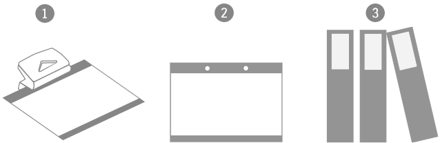
Lightware Visual Engineering supports green technologies and eco-friendly mentality. Thus, this document is made primarily for digital usage. If you need to print out a few pages for any reason, follow the recommended printing settings:
▪Page size: A4
▪Output size: Fit to page or Match page size
▪Orientation: Landscape
TIPS AND TRICKS: Thanks to the size of the original page, a border around the content (gray on the second picture below) makes it possible to organize the pages better. After punching holes in the printed pages, they can easily be placed into a ring folder.
5.5. Limited Warranty Statement
1. Lightware Visual Engineering PLC (Lightware) warrants to all trade and end user customers that any Lightware product purchased will be free from manufacturing defects in both material and workmanship for three (3) years from purchase unless stated otherwise below. The warranty period will begin on the latest possible date where proof of purchase/delivery can be provided by the customer. In the event that no proof can be provided (empty ‘Date of purchase’ field or a copy of invoice), the warranty period will begin from the point of delivery from Lightware.
1.1. 25G and MODEX product series will be subject to a seven (7) year warranty period under the same terms as outlined in this document.
1.2. If during the first three (3) months of purchase, the customer is unhappy with any aspect of a Lightware product, Lightware will accept a return for full credit.
1.3. Any product that fails in the first six (6) months of the warranty period will automatically be eligible for replacement and advanced replacement where available. Any replacements provided will be warranted for the remainder of the original unit’s warranty period.
1.4. Product failures from six (6) months to the end of the warranty period will either be repaired or replaced at the discretion of Lightware. If Lightware chooses to replace the product, then the replacement will be warranted for the remainder of the original unit’s warranty period.
2. The above-stated warranty and procedures will not apply to any product that has been:
2.1. Modified, repaired or altered by anyone other than a certified Lightware engineer unless expressly agreed beforehand.
2.2. Used in any application other than that for which it was intended.
2.3. Subjected to any mechanical or electrical abuse or accidental damage.
2.4. Any costs incurred for repair/replacement of goods that fall into the categories above (2.1., 2.2., 2.3.) will be borne by the customer at a pre-agreed figure.
3. All products to be returned to Lightware require a return material authorization number (RMA) prior to shipment, and this number must be clearly marked on the box. If an RMA number is not obtained or is not clearly marked on the box, Lightware will refuse the shipment.
3.1. The customer will be responsible for in-bound, and Lightware will be responsible for out-bound shipping costs.
3.2. Newly repaired or replaced products will be warranted to the end of the originally purchased product's warranty period.