
USER MANUAL
HDMI-4K Manager
HDMI-4K De-embedder
DA2HDMI-4K-Plus
DA2HDMI-4K-Plus-A
Distribution Amplifier
|
|
|
|
||
|
|
|
|
||
|
|
|
|
||




|
|
|
|
||
|
|
|



Important Safety Instructions
Class II apparatus construction.
The equipment should be operated only from the power source indicated on the product.
To disconnect the equipment safely from power, remove the power cord from the rear of the equipment, or from the power source. The MAINS plug is used as the disconnect device, the disconnect device shall remain readily operable.
There are no user-serviceable parts inside of the unit. Removal of the cover will expose dangerous voltages. To avoid personal injury, do not remove the cover. Do not operate the unit without the cover installed.
The appliance must be safely connected to multimedia systems. Follow instructions described in this manual.
Ventilation
For the correct ventilation and to avoid overheating, ensure enough free space around the appliance. Do not cover the appliance, leave the ventilation holes free and never block or bypass the ventilators (if there are any).
WARNING
To prevent injury, the apparatus is recommended to be securely attached to the floor/wall, or mounted in accordance with the installation instructions. The apparatus shall not be exposed to dripping or splashing, and no objects filled with liquids, such as vases, shall be placed on the apparatus. No naked flame sources, such as lit candles, should be placed on the apparatus.
Waste Electrical & Electronic Equipment (WEEE)

This marking shown on the product or its literature indicates that it should not be disposed with other household wastes at the end of its working life. To prevent possible harm to the environment or human health from uncontrolled waste disposal, please separate this from other types of wastes and recycle it responsibly to promote the sustainable reuse of material resources. Household users should contact either the retailer where they purchased this product or their local government office for details of where and how they can take this item for environmentally safe recycling. Business users should contact their supplier and check the terms and conditions of the purchase contract. This product should not be mixed with other commercial wastes for disposal.
Common Safety Symbols
|
Symbol |
Description |

|
Direct current |

|
Alternating current |

|
Protective conductor terminal |

|
Equipotential Connector |

|
On (Power) |

|
Off (Power) |

|
Double insulation |

|
Caution, possibility of eletric shock |

|
Caution |

|
Laser radiation |

|
Warning, Rotating fan |

|
Caution: for indoor use only |
Applied SW/FW/HW Environment
All presented functions refer to the indicated products. The descriptions have been made while testing these functions in accordance with the indicated Hardware/Firmware/Software environment:
|
Item |
Version |
|---|---|
|
FW package |
v1.0.6b3 |
|
Lightware Device Controller (LDC) version |
v2.22.0b2 |
|
Lightware Device Updater (LDU) version |
v1.5.3b4 |
Document Revision History
|
Rev. |
Release date |
Changes |
Editor |
|
v1 |
2026-04-20 |
Initial release |
Tamas Forgacs |
|
v2 |
2026-09-01 |
ToC correction. |
Laszlo Zsedenyi |
Contact Us
+36 1 255 3800
+36 1 255 3810
Lightware Visual Engineering PLC.
Gizella 51-57, Budapest H-1143, Hungary
©2026 Lightware Visual Engineering. All rights reserved.
All trademarks mentioned are the property of their respective owners.
Specifications are subject to change without notice.
Thank you for choosing Lightware’s DA2HDMI-4K series devices. In the first chapter we would like to introduce the device by highlighting the most important features in the sections listed below:
HDMI-4K Manager
HDMI-4K Manager is a multifunctional interface with built-in EDID Management and Pixel Accurate Reclocking, supporting DVI and HDMI 1.4 signals with or without HDCP encryption. The output signal is reclocked and stabilized using Lightware Pixel Accurate Reclocking technology to remove jitter caused by long cables or poor quality sources.
HDMI-4K De-embedder
HDMI-4K De-embedder is a multifunctional interface, which is capable of audio de-embedding the PCM audio stream. HDMI-4K De-embedder has a built-in EDID Management and Pixel Accurate Reclocking, supporting DVI and HDMI 1.4 signals with or without HDCP encryption. The output signal is reclocked and stabilized using Lightware Pixel Accurate Reclocking technology to remove jitter caused by long cables or poor quality sources.
DA2HDMI-4K-Plus series
DA2HDMI-4K-Plus-A is a multifunctional distribution amplifier with built-in Advanced EDID Management and Pixel Accurate Reclocking, supporting DVI and HDMI 1.4 signals with or without HDCP encryption. The output signal is reclocked and stabilized using Lightware Pixel Accurate Reclocking technology to remove jitter caused by long cables or poor quality sources.
About the Serial Number
Lightware devices contain a label indicating the unique serial number of the product. The structure is the following:
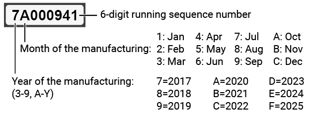
From 1st of October 2024, serial number format of Lightware devices is the following: the first two digits are of the year of manufacture, while the remaining digits make up the running sequence number.

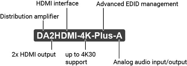
Model Denomination
|
HDMI-4K Manager |
HDMI-4K De-embedder |
DA2HDMI-4K-Plus |
DA2HDMI-4K-Plus-A |
|||
|---|---|---|---|---|---|---|
|
Supplied device |

|
HDMI-4K series device |
|
|
|
|
|
Supplied accessories |
|
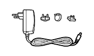
5V DC power adaptor with interchangeable plugs |
|
|
|
|
|
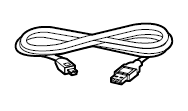
USB cable (USB-A - USB mini-B) |
|
|
|
|
|
|
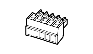
Phoenix Combicon® 5-pole connector |
- |
|
- |
|
|

|
Safety & Warranty Info; Quick Start Guide |
|
|
|
|
|


|
4K Support |
|
High bandwidth allows extension of resolutions up to 4K and even 3D sources and displays are supported. |
|

|
EDID Management |
|
The user can emulate any EDID on the inputs read out and store any attached monitor's EDID in the internal memory. |
|

|
HDCP compliant |
|
The amplifier fulfills the HDCP 1.4 standard. HDCP capability on the digital video input can be disabled when non-protected content is extended. |
|

|
Pixel Accurate Reclocking |
|
Each output has a clean, jitter free signal, eliminating signal instability and distortion caused by long cables or connector reflections. |
|

|
No signal latency |
|
The signal management architecture ensures that there is no delay added between the input and the output. |
|

|
Cable Compensation |
|
Built-in equalizer for signal enhancement to avoid signal attenuation in transmission. |
|

|
Consumer Electronics Control |
|
CEC passthrough is supported on all outputs, transmitting standard CEC commands in order to remote control the source or sink device. |
|
Video interfaces |
Audio interfaces |
|||||
|---|---|---|---|---|---|---|
|
HDMI input |
HDMI output 1 |
HDMI output 2 |
Analog audio input, 3.5mm Jack |
Analog audio output, 5-pole Phoenix |
Analog audio output, 3.5mm Jack |
|
|
|
|

|

|

|
|
|
HDMI-4K Manager |
|
|
- |
- |
- |
- |
|
HDMI-4K De-embedder |
|
|
- |
- |
|
|
|
DA2HDMI-4K-Plus |
|
|
|
- |
- |
- |
|
DA2HDMI-4K-Plus-A |
|
|
|
|
|
|


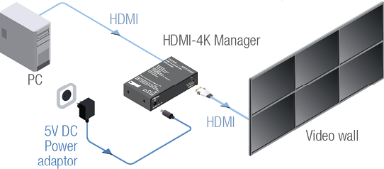
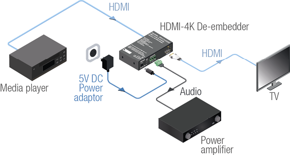
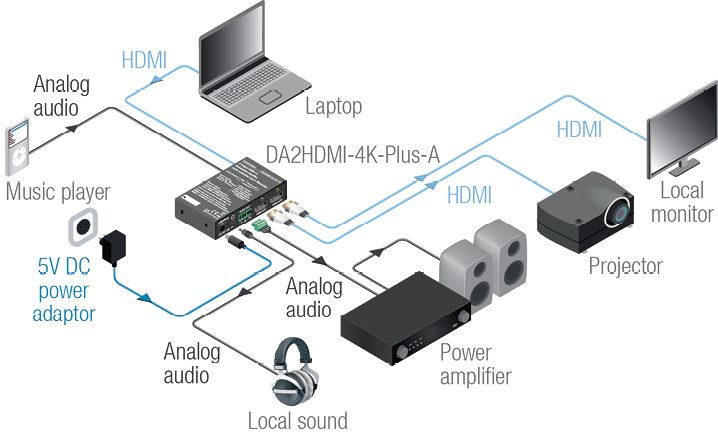
1.5.3. DA2HDMI-4K-Plus Series - Standalone Application
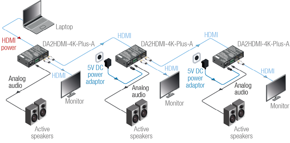
1.5.4. DA2HDMI-4K-Plus Series - Daisy Chain System
The following sections are about the physical structure of the device, input/ output ports and connectors; software and hardware capabilities:
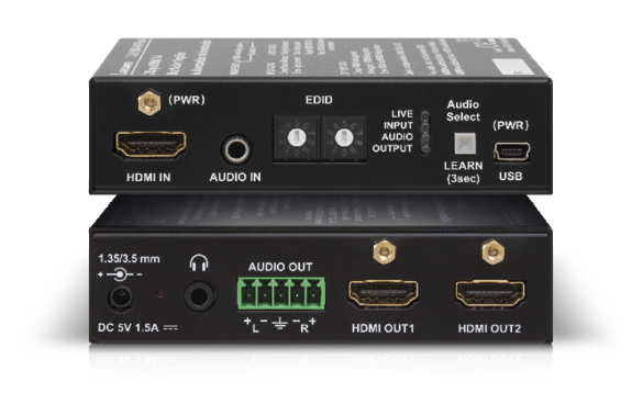
HDMI-4K Manager

HDMI-4K De-embedder

DA2HDMI-4K-Plus

DA2HDMI-4K-Plus-A

|
|
HDMI Input |
HDMI input port for sources and for supplying the device with power (depends on source capabilities). See more details about the powering options of the device in the Powering Options section. The applied cable shall not be more than 20 m (4Kp30) or 30 m (1080p60). |
|
|
Audio Input |
3.5 mm jack connector for asymmetric analog audio signal. Learn more about the connector in the Analog Stereo Audio (Jack) section. |
|
|
Rotary Switches |
Selecting one of the EDID memory addresses. Learn more about it in the Button and Rotary Switches Functions section. |
|
|
Status LEDs |
The LEDs display information about the signal states. See more details in the Status LEDs section. |
|
|
Learn Button (Audio Select) |
Store the EDID of the sink on HDMI OUT1, start the device in Bootload mode, or toggle between the audio sources. |
|
|
USB Control |
USB mini-B type connector to access special settings in the Software Control - Lightware Device Controller software, perform a Firmware Update and supply the unit with power. See more details about the powering options of the device in the Powering Options section. |
|
|
DC Input |
Input for the supplied power adaptor. See more details about the powering options of the device in the Powering Options section. |
|
|
Hidden Button |
Button for restarting the unit. |
|
|
Phones Connector |
3.5mm jack output connector, which is the same as the Analog Audio Output (Phoenix). Learn more about the connector in the Analog Stereo Audio (Jack) section. |
|
|
Analog Audio Output |
5-pole Phoenix connector for balanced analog audio; the signal is de-embedded from the HDMI outputs. Learn more about the connector in the Analog Stereo Audio (Phoenix) section and about the wiring in the Cable Wiring Guide section. |
|
|
HDMI Output |
Connect an HDMI cable between the sink and the unit. |
|
|
HDMI Outputs (mirrored) |
Identical video output ports. Connect an HDMI cable between the sink and the unit. |


|
LIVE |
All Variants |
||

|
off |
Device is not powered. |
|

|
fast blinking (green) |
The device is in Bootload mode. |
|

|
slow blinking (green) |
The device is powered properly and operational. |
|
|
INPUT |
All Variants |
||

|
on (green) |
Source is connected (5V detected). |
|

|
on (orange) |
Signal is present. |
|
|
AUDIO |
All Variants |
||
|
|
off |
No audio is transmitted. |
|

|
on (blue) |
Analog audio input is selected to be embedded in the video stream. |
|

|
on (red) |
HDMI, multichannel / compressed audio signal is detected. |
|

|
on (purple) |
HDMI, PCM 2 channel audio signal is detected. |
|

|
blinking (blue and purple) |
Autoselect is enabled. |
|
|
OUTPUT |
HDMI-4K Manager / HDMI-4K De-embedder |
||
|
|
on (green) |
Hotplug detected on HDMI OUT port. |
|
|
OUTPUT |
DA2HDMI-4K-Plus / DA2HDMI-4K-Plus-A |
||
|
|
on (orange) |
Hotplug detected on HDMI OUT 1. |
|

|
on (yellow) |
Hotplug detected on HDMI OUT 2. |
|
|
|
on (green) |
Hotplug detected on HDMI OUT 1 and HDMI OUT 2. |
|
2.3. Button and Rotary Switches Functions
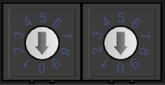
Selecting an EDID
Turn the EDID address rotary switches to the desired position. Use a flat head screwdriver to change the address. The left switch sets the tens value, the right switch gives the ones value of the EDID.
ATTENTION!Avoid the use of keys, coins, knives and other sharp objects.
2.3.2. EDID Learning (OUTPUT LED)
The EDID of the sink connected to HDMI OUT 1 can be stored in the user EDID memory:
Step 1.Turn the EDID rotary switches to the desired position (between #62 - #98).
Step 2.Press the LEARN button and keep it pressed for 3 seconds.
Step 3.The OUTPUT LED turns dark for a second, then provides feedback:
▪BLINKING (green): EDID learning is successful, the EDID is stored.
▪BLINKING (red): EDID learning is failed.
Step 4.The LED turns dark for a second, then shows the state(s) of the connected sink(s).
INFO:Please note that the EDIDs stored in the User EDID memory are deleted when the factory default settings are restored.
Further EDID Options
The following functions are available when connecting to the device by LDC software:
▪EDID learning or importing an EDID, deleting an EDID (from the user memory).
▪Exporting an EDID and saving it as a file.
▪Creating a custom EDID by using the EDID Editor or the Easy EDID Creator.
Learn more about it in the EDID Menu section. The complete list of the EDID memory structure can be found in the Factory EDID List section.
The HDCP setting of the HDMI input port can be enabled/disabled on the front panel as follows:
Step 1.Turn the EDID rotary switches to ‘01’ position.
Step 2.Press the LEARN button and keep it pressed for 3 seconds.
Step 3.The lower three LEDs display if the HDCP state is changed:
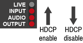
▪HDCP is enabled: LEDs are dark and light up sequentially.
▪HDCP is disabled: LEDs light up and turn dark sequentially.
2.3.4. Restoring the Factory Default Settings
The settings and parameters can be set to factory default as follows:
Step 1.Set the rotary switches to ‘00’ position.
Step 2.Press and keep pressing the LEARN/Audio select button for three seconds. When the lower three LEDs blink, release the button.
See the detailed list about the factory default settings and parameters in the Factory Default Settings section.
This chapter is about the installation of the device and connecting to other appliances, also presenting the mounting options and further assembly steps:
3.1. Mounting Options - Compatibility Table
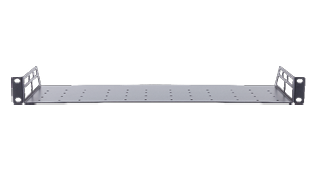
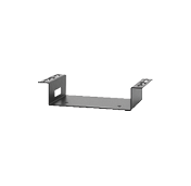
The following table summarizes the compatibility of the TPX series devices with the mounting accessories offered by Lightware. The number in the brackets means how many same-size devices can be assembled to the mounting plate. The dimensions are in mm. The following accessories can be ordered separately, please contact sales@lightware.com for the details.
|
Dimensions |
Model Name |
|
|

|
|
1U High Rack Shelf |
UD Mounting Kit |
UD Mounting Plate F110 |
||
|
100.4 W x 67.6 D x 26 H |
HDMI-4K Manager |
|
|
|
|
HDMI-4K De-embedder |
|
|
|
|
|
DA2HDMI-4K-Plus |
|
|
|
|
|
DA2HDMI-4K-Plus-A |
|
|
|
3.2.1. HDMI Input and Output Ports

The devices are assembled with standard 19-pole HDMI 1.4 connectors with screw lock for inputs and outputs. Always use 22AWG or higher quality HDMI cables for connecting sources and displays.
The HDMI input port can be used for supplying power the device. For more information about the powering options, see the Powering Options section.
3.2.2. Analog Stereo Audio (Jack)

The connector is used for transmitting and receiving unbalanced analog audio signal. It is also known as (3.5 mm or approx. 1/8”) audio jack, phone jack, phone plug and mini-jack plug.

Jack audio plug pin assignments
3.2.3. Analog Stereo Audio (Phoenix)
5-pole Phoenix connector is used for balanced analog audio output. Unbalanced audio devices can be connected as well. See more details about the balanced and unbalanced output port wiring in the Cable Wiring Guide section.

Analog audio connector and plug pin assignments
Compatible Plug Type
Phoenix® Combicon series (3.5mm pitch, 5-pole), type: MC 1.5/5-ST-3.5.

The USB mini-B port allows controlling the device, updating the firmware and supplying power. For more information about the powering options, see the Powering Options section.
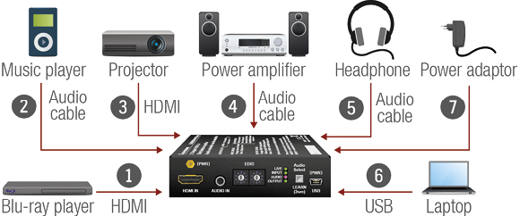
|
|
Connect the desired source to the HDMI input port. |
|
|
Optionally connect an audio source to the Audio input port. |
|
|
Connect one or two sink device(s) to the HDMI output port(s). |
|
|
Optionally connect an audio device (e.g. amplifier) to the Phoenix Audio output port. |
|
|
Optionally connect a headphone to the 3.5 mm Jack Audio output port. |
|
|
Optionally connect a laptop or PC to the USB port and run the LDC software. |
|
|
First connect the power cord of the supplied adaptor to the DC input, then to the AC power socket. |

The device can be powered in any of the following ways:
▪Using the supplied power adaptor (recommended).
▪Connect the device to a proper USB port by the supplied cable.
▪Connecting an HDMI source to the HDMI input port.
ATTENTION!Make sure that the port is able to supply 5V 500 mA current.

Power supplement options port diagram of the HDMI-4K series devices
If the power adaptor is connected, it will supply the device independently from the HDMI/USB ports. If the adaptor is disconnected from the DC input connector, the device tries to use a different power source (HDMI or USB) if it is enabled and connected. (If the adaptor is unplugged from the AC socket but the DC plug is still connected, the device will be switched off and cannot be changed to another power source. Unplug the DC cable from the device to be powered by USB or HDMI.)
ATTENTION!If you are not sure that your USB or HDMI port has enough power, disable the powering over USB and HDMI by Lightware Device Controller software. If the supplied power over USB or HDMI is not enough, the device will switch off. In the case of any strange behavior of the device, please disconnect the USB and HDMI cables and connect the 5V DC adaptor.
INFO:The USB and HDMI powering modes can be enabled/disabled via LDC software. For the details, see the Status section.
The following chapter describes the features of the TPX series devices with a few real-life examples.

Audio/video port diagram of the DA2HDMI-4K-Plus-A
Audio Selection
DIFFERENCE:This section is related to the DA2HDMI-4K-Plus-A variant only.
Press the Audio select (LEARN) button to toggle the audio options.
The device is able to select an audio source automatically: activate the Autoselect mode by the Audio select button. In this case the Analog input port has higher priority: if the Autoselect mode is active and a 3.5mm Jack plug is connected to the Audio input port, it will be embedded into the HDMI stream.
The HDMI-4K series distribution amplifiers can be connected to a PC via USB connection and can be controlled over the Lightware Device Controller (LDC) software.
The following actions can be performed in LDC:
▪HDMI input/output port properties settings, e.g. HDCP, signal type, test pattern
▪Audio crosspoint settings and audio autoselect mode
▪Audio port properties
▪Frame Detector
▪EDID emulation and learning
▪Device status information
▪Configuration backup and restore
▪System settings
For more information about it, see the Software Control - Lightware Device Controller chapter.
4.3. Device Cloning – Configuration Backup and Restore
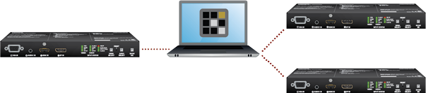
The device (configuration) cloning of a HDMI-4K series distribution amplifier is a simple method that eliminates the need to repeatedly configure certain devices to have identical (non-factory) settings. If the devices are installed in the same type of system multiple times, then it is enough to set up only one device to fit the user’s needs and then copy those settings to the others, thus saving time and resources. See more information about the settings in the Configuration Cloning (Backup Tab) section.
5. Software Control - Lightware Device Controller
The device can be controlled by a computer through the Ethernet and RS-232 ports using Lightware Device Controller (LDC). The software can be installed on a Windows PC or macOS. The application and the User manual can be downloaded from www.lightware.com.
INFO:After the installation, the Windows and the Mac applications have the same look and functionality. This type of the installer is equal to the Normal install in case of Windows and results in an updateable version with the same attributes.
Minimum System Requirement
RAM: 1 GB
Minimum display resolution: 1600x900
Installation for Windows OS
Run the installer. If the User Account Control drops a pop-up message, click Yes.
During the installation you will be prompted to select the type of the installation: normal and the snapshot install:
|
Normal install |
Snapshot install |
|
Available for Windows and macOS |
Available for Windows |
|
The installer can update only this instance |
Cannot be updated |
|
Only one updateable instance can exist for all users |
More than one different version can be installed for all users |
Comparison of installation types
ATTENTION!Using the Normal install as the default choice is highly recommended.
Installation for macOS
Mount the DMG file by double clicking on it, and drag the LDC icon over the Applications icon to copy the program into the Applications folder. If you want to copy the LDC into another location, just drag the icon over the desired folder.
ATTENTION!Please check the firewall settings on the macOS device. LDC needs to be added to the exceptions of the blocked software for the proper operation.
Updating of LDC
Step 1.Run the application.
The Device Discovery window appears automatically, and the program checks the available updates on Lightware’s website and opens the update window if the LDC found updates.
The current and the update version number can be seen at the top of the window and they are shown in this window even with the snapshot install.
The Update window can also be opened by clicking on the About  icon and the Update button.
Step 2.Set the desired update setting in the Options section.
▪If you do not want to check for updates automatically, uncheck the circle that contains the green tick.
▪If you want to postpone the update, a reminder can be set with different delays from the drop down list.
▪If the proxy settings traverse the update process, set the proper values, then click on the OK button.
Step 3.Click on the Download update button to start the updating.
The updates can be checked manually by clicking on the Check now button.
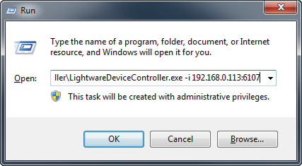
The common way to start the software is to double-click on the LDC icon. But the LDC can be run by command line parameters as follows:
Connecting to a Device with Static IP Address
The LDC is connected to a device with the indicated static IP address directly; the Device Discovery window is not displayed. When the port number is not set, the default port is used: 10001 (LW2 protocol). For LW3, devices use the 6107 port number.
Format: LightwareDeviceController -i <IP_address>:<port>
Example: LightwareDeviceController -i 192.168.0.20:6107
Connecting to a Device via a Serial Port
Format: LightwareDeviceController -c <COM_port>:<Baud>
Example: LightwareDeviceController -c COM1:57600
The LDC is connected to a device with the indicated COM port directly; the Device Discovery window is not displayed. If no Baud rate is set, the application will detect it automatically.
Adjusting the Zoom
The window can be zoomed to a specific value to fit to the resolution of the desktop (higher/lower). '1' is the default value (100%).
Format: LightwareDeviceController -z <magnifying_value>
Example: LightwareDeviceController -z 1.2
ATTENTION!The last set value is stored and applied when LDC is started without a parameter.
5.3. Connecting to a Device (Device Discovery Window)
Connecting Steps
Step 1.Connect the device to a computer via USB.
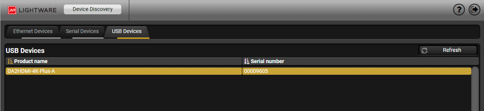
Step 2.Run the controller software; the device discovery window appears automatically. There are three tabs for the different types of interfaces: Ethernet, Serial, and USB.
Step 3.Go to the USB tab and select the desired unit and click on the green Connect button (or just double-click on the device).
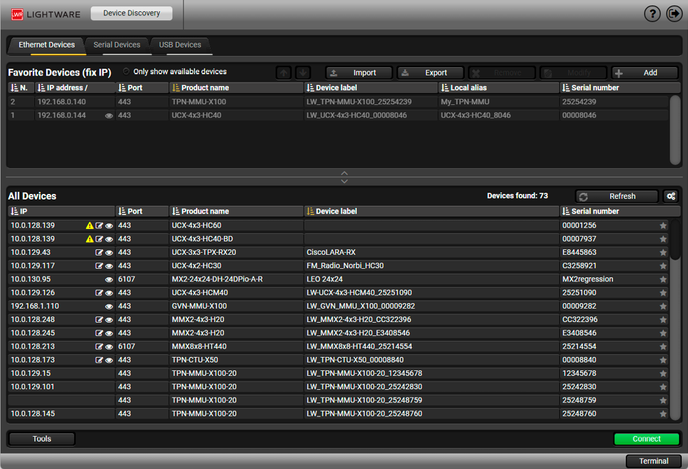
Device Discovery window
Connect the device to a PC/computer over the USB mini B-type connector. Refresh the list and double-click on the device or select it and click on the green Connect button.
The Tools menu contains the following options:
▪Log Viewer: The tool can be used for reviewing log files that have been saved previously.
▪Create EDID: This tool opens the Easy EDID Creator wizard, which can be used for creating unique EDIDs in a few simple steps. Functionality is the same as that of the Easy EDID Creator.
▪Demo Mode: This is a virtual MX-FR17 matrix router with full functionality built into the LDC. Functions and options are the same as that of a real MX-FR17 device.
▪Bulk Management: This tool allows changing the network settings of several devices at once - it is not applicable for the HDMI-4K series devices.
The Terminal window is also available by pressing its button on the bottom.
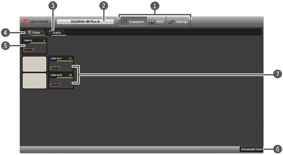
|
|
Main menu |
The available menu items are displayed. The active one is shown with a dark grey background color. |
|
|
Information ribbon |
The label shows the device label, which can be edited in the Settings menu - Status tab. The Device discovery window can be displayed by clicking on this ribbon. |
|
|
Audio tab |
Leading to the Audio crosspoint settings. |
|
|
Video tab |
Leading to the Video crosspoint settings. |
|
|
Video input port |
The tile represents a video input port. The tile below the port shows the current crosspoint setting; if the port is switched to the output, the color of the tile is white, otherwise grey. See more details in the Video Input Port Properties Panel section. |
|
|
Advanced view |
Displaying the Advanced View Window, showing the Terminal window and the LW3 protocol tree. |
|
|
Video output port(s) |
The tile represents a video input port. The tile below the port shows the current crosspoint setting; if the port is switched to the output, the color of the tile is white, otherwise grey. See more details in the Video Output Port Properties Panel section. |
Port Tiles #status
The colors of the port tiles and the displayed icons represent different states and information:
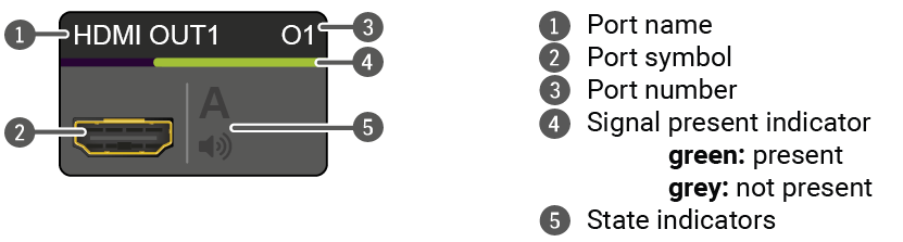
State Indicators
Following icons display different states of the port/signal:
|
Icon |
Icon is grey |
Icon is black |
Icon is green |

|
Signal is not encrypted with HDCP |
Signal is encrypted with HDCP |
- |
|
|
Audio signal is unmuted |
Audio signal is muted |
- |

|
Autoselect is disabled |
- |
Autoselect is enabled |

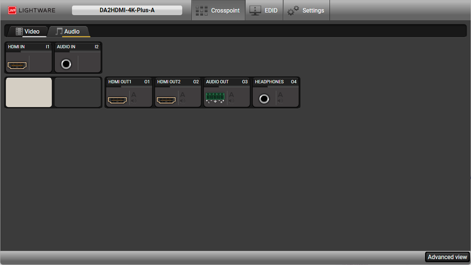
Crosspoint menu - Audio tab
Crosspoint Setting
The audio signal source of the HDMI output port(s) and the analog audio ports can be set:
▪the audio signal of the HDMI input port, or
▪the audio signal of the analog audio input port
DIFFERENCE:Only the DA2HDMI-4K-Plus-A model is built with Analog audio input port.
DIFFERENCE:Only the HDMI-4K De-embedder and the DA2HDMI-4K-Plus-A modesl are built with Analog audio output ports.
Port Properties
Clicking on the port tile opens the Port properties window. See more details in the Analog Audio Input Port Properties Panel and the Analog Audio Output Port Properties Panel sections.
Clicking on the port tile opens the Port properties window. This section shows the available settings and status information by port types.
5.5.1. Video Input Port Properties Panel
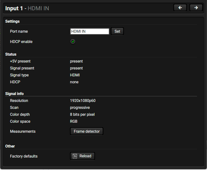
HDMI input port properties panel
Available Information and Settings
▪Port name;
▪HDCP enable/disable settings;
▪Status and Signal Info;
5.5.2. Video Output Port Properties Panel
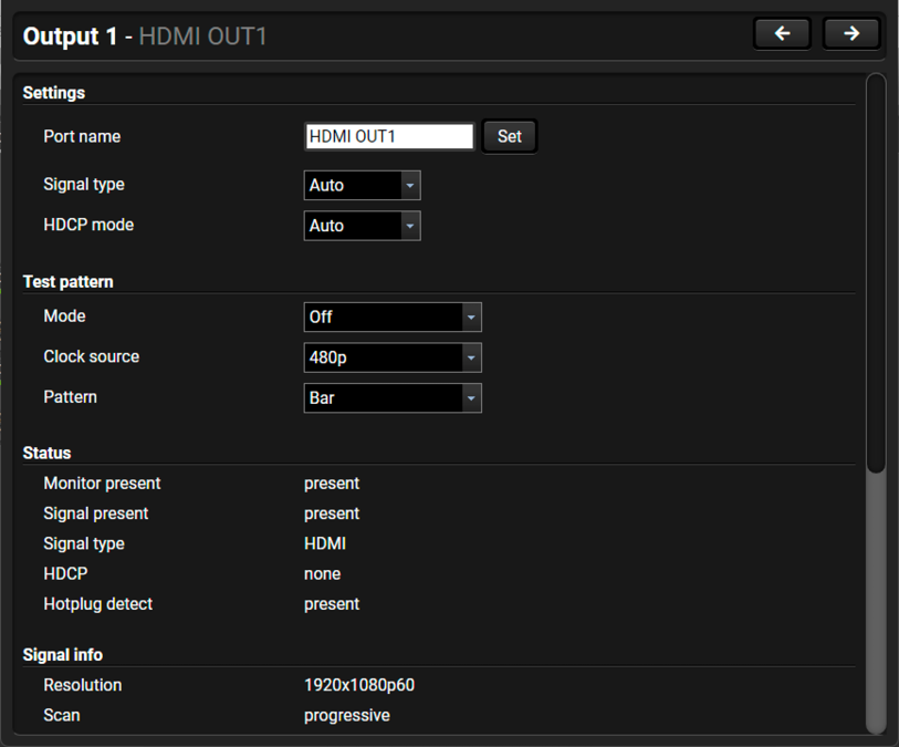
HDMI input port properties panel
Available Information and Settings
▪Port name;
▪Signal type: Auto / DVI / HDMI 24bit;
▪HDCP mode: Auto / Always;
▪Test pattern:
=Mode: Off / On / No signal;
=Clock source: 480p / 576p / Original video signal
=Pattern: Red / Green / Blue / Black / White / Ramp / Chess / Bar / Cycle
▪Status and Signal Info;
▪Display information.
5.5.3. Analog Audio Input Port Properties Panel
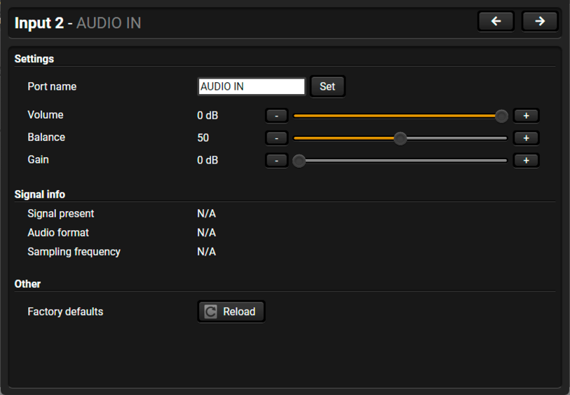
Analog audio input port (Jack) properties panel
Available Information and Settings
▪Port name;
▪Volume setting: between -57 dB and 0 dB;
▪Balance setting: between 0 and 100 (center is 50);
▪Gain setting: between 0 dB and 6 dB.
▪Signal info.
5.5.4. Analog Audio Output Port Properties Panel
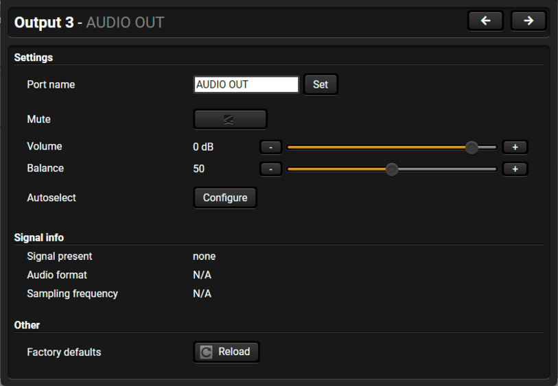
Analog audio output port (Phoenix) properties panel
Available Information and Settings
▪Port name;
▪Mute/unmute button;
▪Volume setting: between -57 dB and +6dB;
▪Balance setting: between 0 and 100 (center is 50);
▪Autoselect setting - see the details in the Autoselect Panel section (on the right);
▪Signal info.
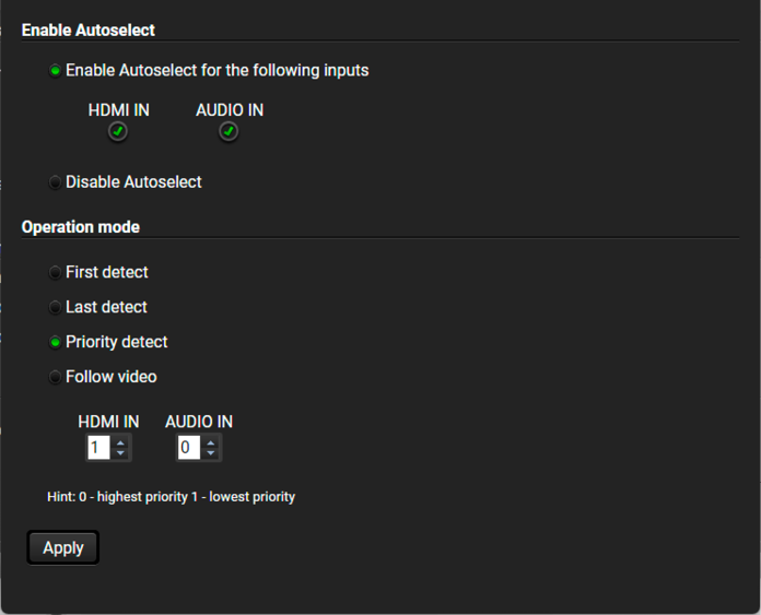
Autoselect panel
There are three types of Autoselect as follows:
▪First detect mode: selected input port is kept connected to the output as long as it has an active signal.
▪Priority detect mode: it is always the highest priority active input that is selected to transmit.
▪Last detect mode: it is always the last attached input that is selected to transmit.
The ports can show detailed information about the signal, like full size and active video resolution. This feature is a good troubleshooter if compatibility problems occur during system installation. To access this function, open the port properties window and click on the Frame detector button.
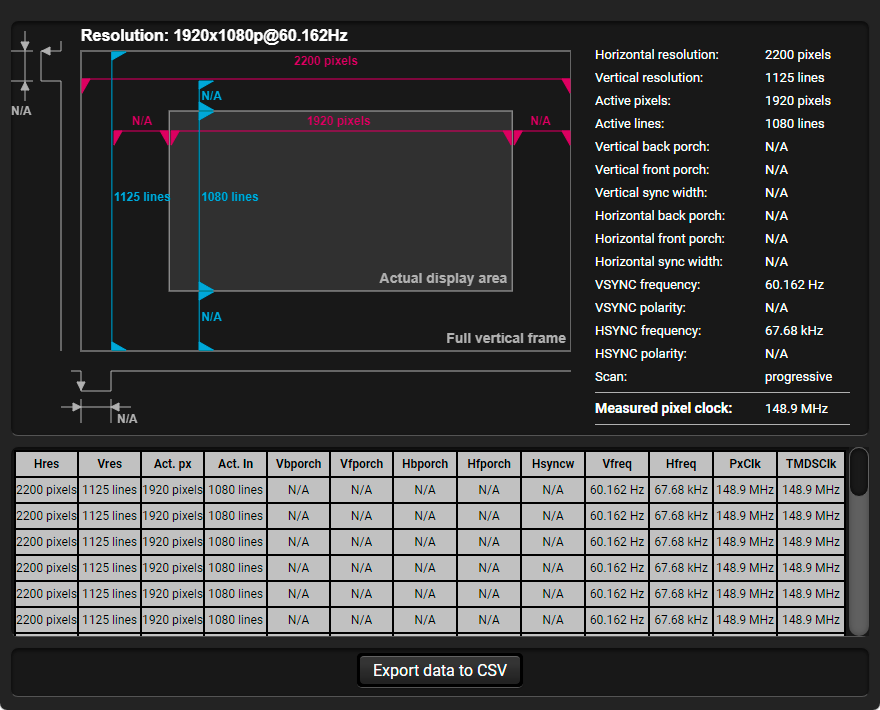
Frame detector window
Lightware’s Frame Detector function works like a signal analyzer and makes it possible to determine the exact video format that is present on the port, thus helps identify many problems. E.g. actual timing parameters may differ from the expected and this may cause some displays to drop the picture.
Frame Detector measures detailed timings on the video signals just like a built-in oscilloscope, but it is much easier to use. The actual display area shows the active video size (light grey). The dark grey area of the full frame is the blanking interval, which can contain the info frames and embedded audio data for HDMI signals. Shown values are measured directly on the signal and not retrieved only from the HDMI info frames.
Advanced EDID Management can be accessed by selecting the EDID menu. There are two panels: the left one contains Source EDIDs, the right one contains Destination places where the EDIDs can be emulated or copied.
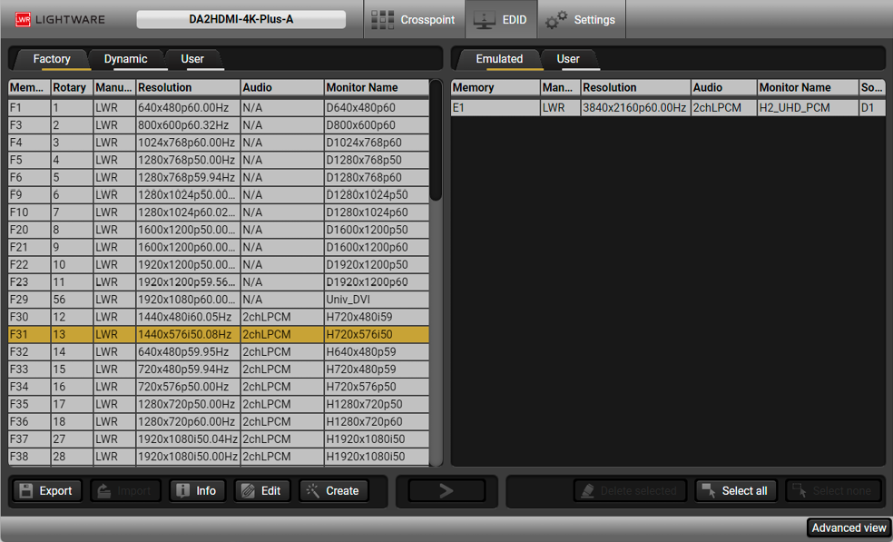
EDID menu
Control Buttons

|
Exporting an EDID (save to a file) |

|
Transfer button: executing EDID emulation or copying |

|
Importing an EDID (load from a file) |

|
Deleting EDID (from User memory) |

|
Display EDID Summary window |

|
Selecting all memory places in the right panel |

|
Opening Advanced EDID Editor with the selected EDID |

|
Selecting none of the memory places in the right panel |

|
Opening Easy EDID Creator |
Changing Emulated EDID
Step 1.Choose the desired EDID list on the source panel and select an EDID.

Step 2.Press the Emulated button on the top of the Destination panel.
Step 3.Select the desired port on the right panel (one or more ports can be selected); the EDID(s) will be highlighted in yellow.
Step 4.Press the Transfer button to change the emulated EDID.
Learning an EDID
The process is the same as changing the emulated EDID; the only difference is the Destination panel: press the User button. Thus, one or more EDIDs can be copied into the user memory either from the factory memory or from a connected sink (Dynamic).
Exporting an EDID

ATTENTION!This function is working on Windows and macOS operating systems and under Firefox or Chrome web browsers only.
Source EDID can be downloaded as a file (*.bin, *.dat or *.edid) to the computer.
Step 1.Select the desired EDID from the Source panel (the line will be highlighted in yellow).
Step 2.Press the Export button to open the dialog box and save the file to the computer.
Importing an EDID

Previously saved EDID (*.bin, *.dat or *.edid file) can be uploaded to the user memory:
Step 1.Press the User button on the top of the Source panel and select a memory slot.
Step 2.Press the Import button below the Source panel.
Step 3.Browse the file in the opening window then press the Open button. Browsed EDID is imported into the selected User memory.
ATTENTION!The imported EDID overwrites the selected memory place even if it is not empty.
Deleting EDID(s)
The EDID(s) from User memory can be deleted as follows:

Step 1.Press the User button on the top of the Destination panel.

Step 2.Select the desired memory slot(s); one or more can be selected (“Select All” and “Select None” buttons can be used). The EDID(s) will be highlighted in yellow.
Step 3.Press the Delete selected button to delete the EDID(s).


Select an EDID from Source panel and press the Info button to display the EDID summary.
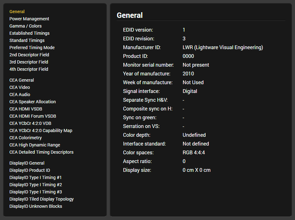
EDID summary window

Select an EDID from the Source panel and press the Edit button to display the Advanced EDID Editor window. The editor can read and write all descriptors that are defined in the standards, including the additional CEA extensions. Any EDID from the device’s memory or a saved EDID file can be loaded into the editor. The software resolves the raw EDID and displays it as readable information to the user. All descriptors can be edited, saved in an EDID file, or uploaded to the User memory. For more details about the EDID Editor, please visit our website and download the EDID Editor Application Notes.
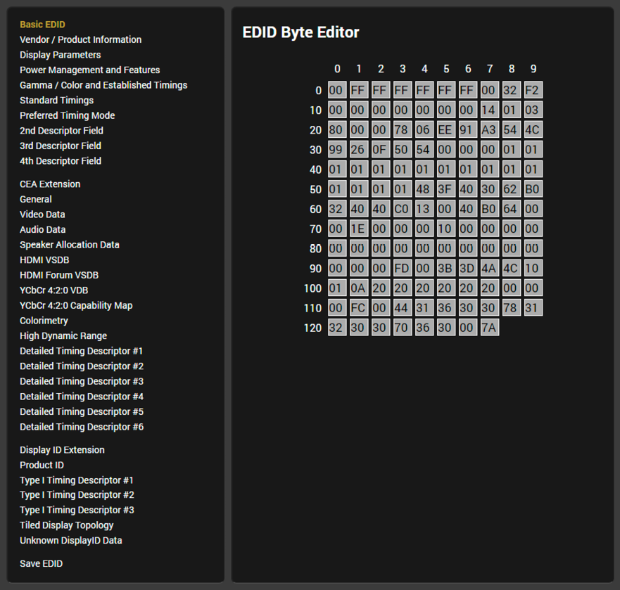
EDID Editor window
5.6.4. Creating an EDID - Easy EDID Creator

Since the Advanced EDID Editor mentioned above needs more complex knowledge about EDID, Lightware introduced a wizard-like interface for fast and easy EDID creation. With Easy EDID Creator, it is possible to create custom EDIDs in four simple steps. By clicking on the Create button below the Source panel, Easy EDID Creator is opened in a new window. For more details about the EDID Editor, please visit our website and download the EDID Editor Application Notes.
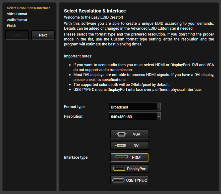
EDID Creator window
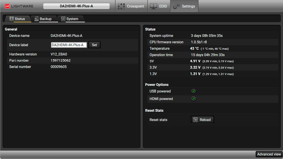
Settings menu - Status tab
The most important hardware and software related information can be found on this tab: hardware and firmware version, serial numbers, temperatures, operation time, and voltage information. Device label can be changed to a unique description by the Set button.
Available Settings
▪USB powered - if it is checked, USB powering mode is allowed.
▪HDMI powered - if it is checked, HDMI 5V powering mode is allowed.
Details about this function can be found in the Configuration Cloning (Backup Tab) section (next page).
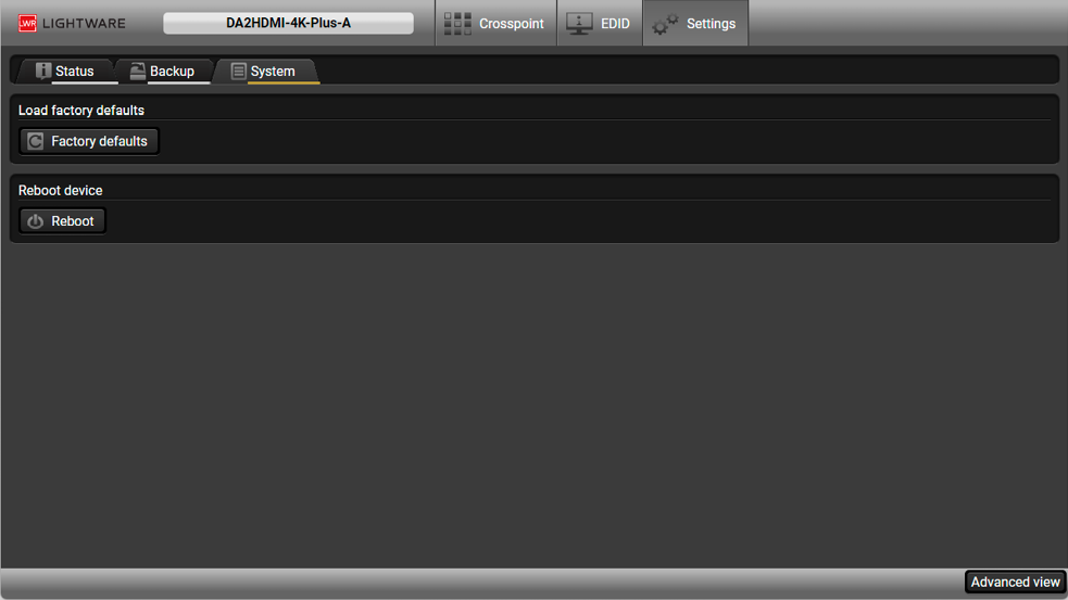
Settings menu - System tab
Available Settings
▪Load factory defaults - recalling factory default settings and values. All factory default settings are listed in the Factory Default Settings section.
▪Reboot - rebooting the device.
5.8. Configuration Cloning (Backup Tab)
Configuration cloning of Lightware LW3 devices is a simple method that eliminates the need to repeatedly configure certain devices to have identical (non-factory) settings. If the devices are installed in the same type of system multiple times, then it is enough to set up only one device to fit the user’s needs and then copy those settings to the others, thus saving time and resources.
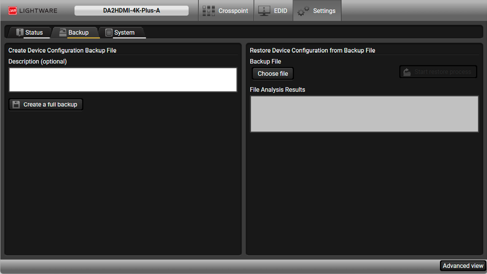
Backup tab in the Settings menu
Installing multiple devices with the same customized configuration settings can be done in a few easy steps:
Step 1.Configure one device with all your desired settings using the LDC software.
Step 2.Backup the full configuration file to your computer.
Step 3.Connect to the other device that needs to be configured and upload (restore) your configuration file.
Step 4.Done! You can have as many totally identical, customized devices as you like.
ATTENTION!Macros cannot be saved into the backup file. If you have macros stored in a Configuration slot, download it separately and upload it into the target device.
5.8.2. Save the Settings of a Device (Backup)
Step 1.Apply the desired settings in the transmitter (port parameters, crosspoint, etc.)
Step 2.Select the Settings / Backup tab from the menu.
Step 3.Write a short description in the text box on the left (optional).
Step 4.Press the Create a full backup button. You will be prompted to save the file to the computer. The default file name is the following:
BACKUP_<DEVICE TYPE>_SN<SERIAL NUMBER>.LW3
Step 5.Set the desired file name, select the folder and save the file.
TIPS AND TRICKS:Using the exact product type in the filename is recommended, since it makes the file usage more comfortable.
About the Backup File
The backup file is a simple text file, which contains LW3 protocol commands. The first line is the description and the further lines are the commands that will be executed during the restoration process. The file can be viewed (and/or edited) by a simple text editor, e.g. Notepad.
ATTENTION!Editing the command lines is only recommended for expert users.
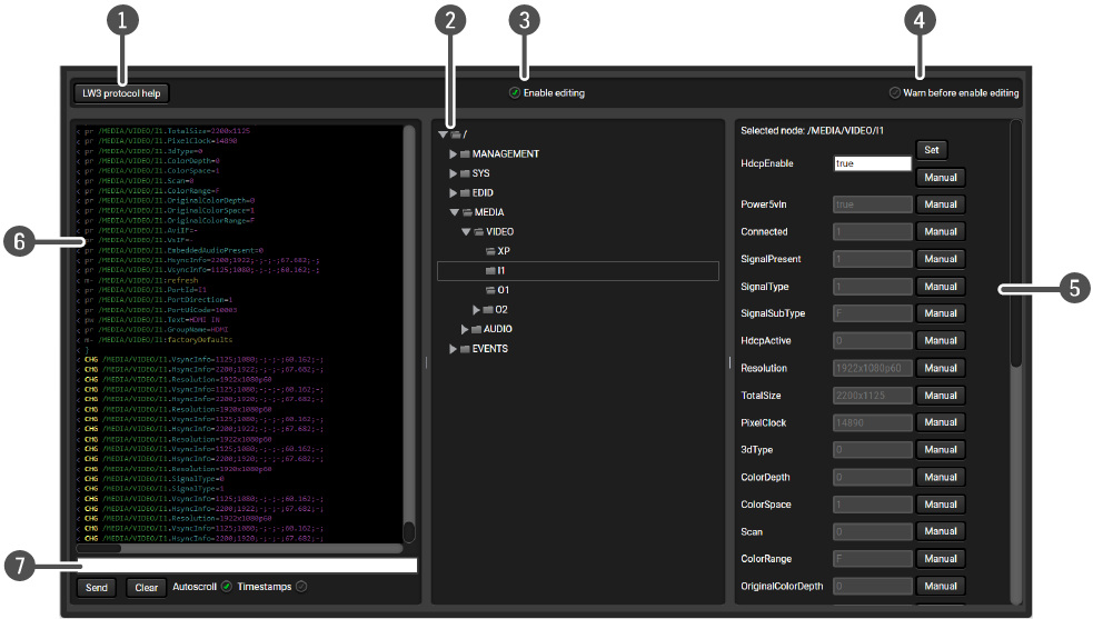
|
|
LW3 protocol help |
Pushing the button opens a help window that displays the most important information about LW3 protocol commands in HTML format. |
|
|
|
Protocol tree |
LW3 protocol tree; select an item to see its content. |
|
|
|
Edit mode |
The default appearance is the read-only mode. If you want to modify the values or parameters, tick the option. You will be prompted to confirm your selection. |
|
|
|
Warning mode |
If this is checked, a warning window pops up when you enable Edit mode. |
|
|
|
Node list |
Correspondent parameters and nodes are shown that are connected to the selected item in the protocol tree. The commands typed in these fields are escaped automatically |
|
|
Manual button: |
Manual (short description) of the node can be called and displayed in the terminal window. |
||
|
Set button: |
Saves the value/parameter typed in the textbox. |
||
|
Call button: |
Calls the method, e.g. reloads factory default settings. |
||
|
|
Terminal window |
Commands and responses with time and date are listed in this window. The sent command starts with ‘>’ character, the received response starts with ‘<’ character. The color of each item depends on the type of the command and response. The content of the window can be emptied by the Clear button. If the Autoscroll option is ticked, the list is scrolled automatically when a new line is added. |
|
|
|
Command line |
The commands typed in this line are not escaped automatically. |
|


This chapter is meant to help customers perform firmware updates on our products by giving a few tips on how to start and by explaining the features of the Lightware Device Updater (LDU) software. The latest software and firmware pack can be downloaded from www.lightware.com.
6.1. About the Firmware Package (LFP File)

The firmware files are packed in an LFP package. You need only this file to do the update on your device.
▪The package contains all the necessary components, binary, and other files; You do not have to get further files.
▪There is a descriptor file in the package that contains each firmware with version number and a list showing the compatible devices. The descriptor is displayed after loading the LFP file in the LDU.
Step 1.Get the firmware pack and the Lightware Device Updater (LDU) application.
Step 2.Install the LDU application.
Step 3.Establish the connection between the computer and the device(s).
Step 4.Start the LDU and follow the instructions shown on the screen.
Installation for Windows OS

INFO:The application can be installed under Windows XP or above.
Run the installer. If the User Account Control drops a pop-up message, click Yes. During the installation you will be prompted to select the type of the installation:
|
Normal install |
Snapshot install |
|
Available for Windows and macOS |
Available for Windows |
|
The installer can update only this instance |
Cannot be updated |
|
Only one updateable instance can exist for all users |
More than one different version can be installed for each user |
Comparison of install types
ATTENTION!Using the Normal install as the default value is highly recommended.
Installation for macOS

INFO:After the installation the Windows and the macOS applications have the same look and functionality. This type of the installer is equal to the Normal install in case of Windows and results in an updateable version with the same attributes.
Mount the DMG file by double clicking on it, and drag the LDU icon over the Applications icon to copy the program into the Applications folder. If you want to copy the LDU into another location, just drag the icon over the desired folder.
LDU Update

Step 1.Run the application. In the welcome screen click on the button in the top right corner; the About window will appear. Click on the Check now button. The program checks the available updates on the Lightware website and shows its version.
Step 2.Set the desired update settings in the Options section.
▪If you do not want to check for the updates automatically, uncheck the circle that contains the green tick.
▪If you want to postpone the update, a reminder can be set with different delays from the drop down list.
▪If the proxy settings traverse the update process, set the proper values then click the OK button.
Step 3.Press the Update button to download the new version; the installer will start.
6.4.1. Establish the Connection
Make sure that the computer and the device are connected via USB. If you connect a device, it must be in Configuration mode.
6.4.2. Start the LDU and Follow the Instructions
After launching LDU, the welcome screen will appear. Pressing the  button, a list will appear, showing the supported devices. Click on the Extender button on the main screen.
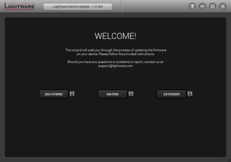
Welcome screen
Performing the Update
ATTENTION!The device must be supplied with the power adaptor when the firmware is updated. Supplying the device over USB or HDMI is not recommended for this process.
Step 1.Connect a PC/laptop to the USB port of the device by the supplied USB cable.
Step 2.Start the LDU software and follow the instructions shown on the screen.
Starting the Unit in Bootload Mode
If the usual firmware update cannot be performed for any reason, try the following:
Step 1.Press the LEARN button and keep it pressed.
Step 2.Press and release the hidden button.
Step 3.Release the LEARN button. The device is restarted in bootload mode. The LIVE LED blinks fast.
The following sections contain descriptions and useful technical information on how the devices work in the background. The content is based on experiences and cases we met in the practice. These sections help to understand features and technical standards like the following:
The Extended Display Identification Data (EDID) is the passport of display devices (monitors, TV sets, projectors). It contains information about the capabilities of the display, such as supported resolutions, refresh rates (these are called Detailed Timings), the type and manufacturer of the display device, etc.
After connecting a source to a display (DVI, HDMI, DP), the source reads out the EDID to determine the resolution and refresh rate of the image to be transmitted.
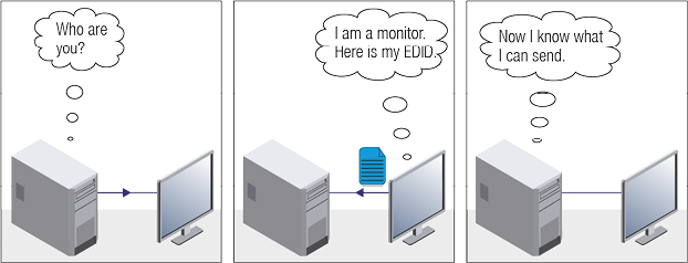
EDID communication
Most DVI computer displays have a 128-byte-long EDID structure. However, Digital Televisions and HDMI capable displays may have another 128 bytes, which is called E-EDID and defined by CEA (Consumer Electronics Association). This extension contains information about additional Detailed Timings, audio capabilities, speaker allocation and HDMI capabilities. It is important to know that all HDMI capable devices must have CEA extension, but not all devices with CEA extension are HDMI capable.
Common Problems Related to EDID
Problem: “My system consists of the following: a computer, a Lightware device, a WUXGA (1920x1200) LCD monitor, and an SXGA (1280x1024) projector. I would like to see the same image on the monitor and the projector. What EDID should I choose on the Lightware device?”
Solution: If you want to see the image on both displays, you need to select the resolution of the smaller display (in this case SXGA), otherwise the smaller display may not show the higher resolution image.
Problem: “I have changed to a different EDID on an input port of the Lightware device to have a different resolution, but nothing happens.”
Solution: Some graphics cards and video sources read out the EDID only after power-up, and later they do not sense that the EDID has been changed. You need to restart your source to make it read out the EDID again.
7.1.2. Advanced EDID Management
Each DVI sink (e.g. monitors, projectors, plasma displays, etc...) must support the EDID data structure. Source BIOS and operating systems are likely to query the sink using DDC2B protocol to determine what pixel formats and interface are supported. DVI standard uses EDID data structure to identify the monitor type and capabilities. Most DVI sources (VGA cards, set top boxes, etc.) will output DVI signal after accepting the connected sink’s EDID information. In the case of EDID readout failure or missing EDID, the source will not output DVI video signal.
Lightware devices provide the Advanced EDID Management function that helps system integration. The built-in EDID Router can store and emulate factory pre-programmed- and User programmable EDIDs. The EDID of the attached monitors or projectors for each output are stored in a non-volatile memory. This way, the EDID of a monitor is available when the monitor is unplugged or switched off.
Any EDID can be emulated on any input. An emulated EDID can be copied from the EDID router’s memory (static EDID emulation), or from the last attached monitor’s memory (dynamic EDID emulation). For example, the Lightware device can be set up to emulate a sink device, which is connected to one of the outputs. In this case, the EDID automatically changes if the monitor is replaced with another display device (as long as it has a valid EDID).
The EDID is independently programmable for all inputs without affecting each other. All inputs have their own EDID circuit.
INFO:The user is not required to disconnect the video cable to change an EDID as opposed to other manufacturer’s products. The EDID can be changed even if a source is connected to the input and powered ON.
INFO:When the EDID has been changed, the router toggles the HOTPLUG signal for 2 seconds. Some sources do not sense this signal. In such cases, the source device must be restarted or powered OFF and ON again.
Lightware Visual Engineering is a legal HDCP adopter. Several functions have been developed, which helps to solve HDCP related problems. Complex AV systems often have both HDCP and non-HDCP components. The matrix allows transmitting HDCP encrypted and unencrypted signals. The devices will be still HDCP compliant, as they will never output an encrypted signal to a non-HDCP compliant display device. If an encrypted signal is switched to a non-compliant output, a red screen alert or muted screen will appear.
7.2.1. Protected and Unprotected Content
Many video sources send HDCP protected signal if they detect that the sink is HDCP capable – even if the content is not copyrighted. This can cause trouble if an HDCP capable device is connected between the source and the display. In this case, the content cannot be viewed on non-HDCP capable displays and interfaces like event controllers. Rental and staging technicians often complain about certain laptops, which are always sending HDCP encrypted signals if the receiver device (display, matrix router, etc.) reports HDCP compliancy. Even though HDCP encryption is not required all the time (e.g. computer desktop image), certain laptops still do that.
To avoid unnecessary HDCP encryption, Lightware introduced the HDCP enabling/disabling function: the HDCP capability can be disabled in the Lightware device. If HDCP is disabled, the connected source will detect that the sink is not HDCP capable, and turn off authentication.
7.2.2. Disable Unnecessary Encryption
HDCP Compliant Sink
All the devices are HDCP-compliant, no manual setting is required, both protected and unprotected contents are transmitted and displayed on the sink.

Not HDCP-compliant Sink 1.
Not-HDCP compliant sink is connected to the matrix. Some sources (e.g. computers) always send HDCP encrypted signals if the receiver device reports HDCP compliancy, however, HDCP encryption is not required all the time (e.g. computer desktop image). If HDCP is enabled in the matrix, the image will not be displayed on the sink.
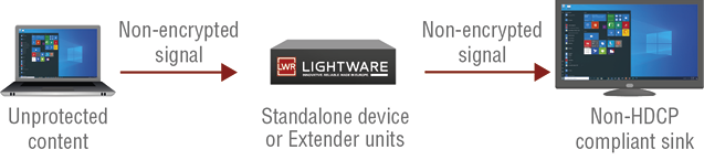
Setting the HDCP parameter to Auto on the output port and disable HDCP on the input port, the transmitted signal will not be encrypted if the content is not protected. Thus, non-HDCP compliant sinks will display non-encrypted signal.
Not HDCP-compliant Sink 2.
The layout is the same as in the previous case: non-HDCP compliant display device is connected to the matrix but the source would send protected content with encryption. If HDCP is enabled on the input port of the matrix, the source will send encrypted signal.
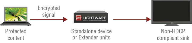
The sink is not HDCP compliant, thus it will not display the video signal, but blank screen is shown. If HDCP is disabled on the input port of the matrix, the source will not send the signal. The solution is to replace the display device with an HDCP-capable one.
7.3. Pixel Accurate Reclocking
Signal reclocking is an essential procedure in digital signal transmission. After passing the reclocking circuit, the signal becomes stable, jitter-free, and can be transmitted over more equipment like processors or event controllers. Without reclocking, sparkles, noise, and jaggies appear on the image.
Lightware’s sophisticated Pixel Accurate Reclocking technology fixes more problems than general TMDS reclocking. It removes not only intra-pair skew, but inter-pair skew as well. The Pixel Accurate Reclocking circuit eliminates the following errors:
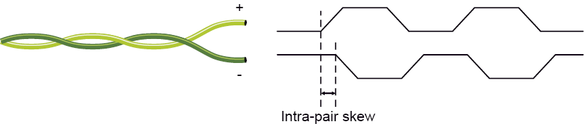
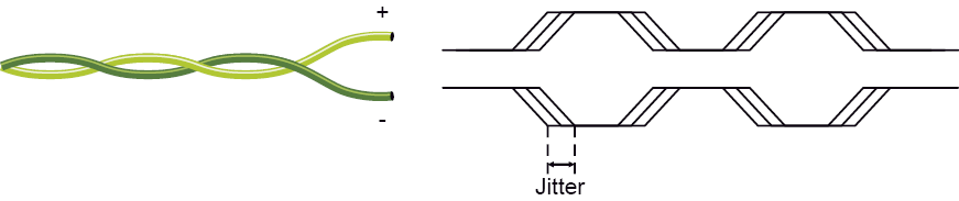
Intra-pair skew
Skew between the + and - wires within a differential wire pair (e.g. Data2- and Data2+). It’s caused by different wire lengths or slightly different wire construction (impedance mismatch) in the DVI cable. It results in jitter.
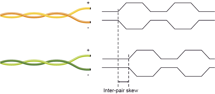
Inter-pair skew
Skew between two differential wire pairs in a cable. It is caused by different wire pair lengths or different number of twists in the DVI cable. Too much inter-pair skew results in color shift in the picture or sync loss.
Jitter
Signal instability in the time domain. The time difference between two signal transitions should be a fixed value, but noise and other effects cause variations.
Noise
Electromagnetic interference between other electronic devices such as mobile phones, motors, etc. and the DVI cable are coupled onto the signal. Too much noise results in increased jitter.

Tables, drawings, guides, technical details and the hashtag keyword list as follows:
INFO:Specifications are subject to change without notice.
General
|
Compliance |
CE, UKCA |
|
EMC (emission) |
EN 55032:2015+A1:2020 |
|
EMC (immunity) |
EN 55035:2017+A11:2020 |
|
RoHS |
EN 63000:2018 |
|
Electrical safety |
EN 62368-1:2024 |
|
Warranty |
3 years |
|
Cooling |
Passive |
|
Operating temperature |
0 to +50˚C (+32 to +122˚F) |
|
Storage temperature |
-40° to +85˚C (-40° to +185˚F) |
|
Operating humidity |
10% to 90%, non-condensing |
Power
|
Power supply option |
External power adaptor / USB port / HDMI input port |
|
Supported power source |
100-240 V AC; 50/60 Hz |
|
Supplied power |
5V DC, 3A |
|
AC power plug |
Interchangable (EU, UK, JP/US, AUS/NZ) |
|
DC power plug |
DC connector (2.5/5.5 mm pin) |
|
Power consumption |
1.8 W |
|
Heat dissipation |
6.14 BTU/h |
Enclosure
|
Rack mountable |
Yes, with mounting accessories, check the Mounting Options - Compatibility Table |
|
Enclosure material |
1 mm steel |
|
Dimensions in mm |
100.4 W x 67.6 D x 26 H |
|
Dimensions in inch |
4 W x 2.7 D x 1 H |
|
Weight |
250 g (0.55 lbs) |
Video Input
HDMI Input
|
Connector type |
19-pole HDMI Type A receptacle |
|
Number of ports |
1 |
|
Standard |
DVI 1.0, HDMI 1.4 |
|
HDCP compliance |
HDCP 1.4 |
|
Color space |
RGB, YCbCr |
|
Video delay |
0 frame |
|
Supported resolutions at 8 bits/color * |
up to 4096x2160@30Hz (4:4:4) or up to 4096x2160@60Hz (4:2:0) |
|
Audio formats |
8 channel PCM / Dolby TrueHD, DTS-HD Master Audio 7.1 |
|
Reclocking |
Pixel Accurate Reclocking |
|
3D support |
yes |
|
Input cable equalization |
Yes, +12dB fixed |
|
Cable length (input port) |
max 20 m (4Kp30) or 30 m (1080p60) |
Video Output
HDMI Outputs
|
Connector type |
19-pole HDMI Type A receptacle |
|
Number of ports - HDMI-4K Manager / HDMI-4K De-embedder |
1 |
|
Number of ports - DA2HDMI-4K-Plus / DA2HDMI-4K-Plus-A |
2 |
|
Standard |
DVI 1.0, HDMI 1.4 |
|
HDCP compliance |
HDCP 1.4 |
|
Color space |
RGB, YCbCr |
|
Video delay |
0 frame |
|
Supported resolutions at 8 bits/color * |
up to 4096x2160@30Hz (4:4:4) or up to 4096x2160@60Hz (4:2:0) |
|
Audio formats |
8 channel PCM / Dolby TrueHD, DTS-HD Master Audio 7.1 |
|
Reclocking |
Pixel Accurate Reclocking |
|
3D support |
yes |
|
Control over CEC |
HDMI out 1: no CEC control; HDMI out 2: transparent |
* All standard VESA, CEA and other custom resolutions up to 300MHz (HDMI 1.4) are supported.
Audio Input
DIFFERENCE:Only for DA2HDMI-4K-Plus-A model.
Analog Audio Input
|
Audio port connector |
3.5mm TRS (1/8” jack) |
|
Number of ports |
1 |
|
Audio formats |
2-channel PCM |
|
Sampling frequency |
48 kHz |
|
Maximum input level |
+0 dBu, 0.77 Vrms, 2.19 Vpp |
|
Signal transmission |
Balanced / unbalanced signal |
|
Volume |
-95 - 0 dB |
|
Balance |
0 - 100 (50 = center) |
|
Gain |
0 dB - +6 dB |
Audio Output
Analog Audio Output (Phoenix)
DIFFERENCE:Only for HDMI-4K De-embedder and DA2HDMI-4K-Plus-A models.
|
Audio port connector |
5-pole Phoenix® connector |
|
Number of ports |
1 |
|
Audio formats |
2-channel PCM |
|
Sampling frequency |
48 kHz |
|
Signal transmission |
Balanced / unbalanced signal |
|
Volume |
-57 - +6 dB |
|
Balance |
0 - 100 (50 = center) |
|
Nominal Differential Output Level @ 0 dB Gain |
+4 dBu |
|
Nominal Differential Output Level @ 3 dB Gain |
+7 dBu |
Analog Audio Output (Jack)
DIFFERENCE:Only for HDMI-4K De-embedder and DA2HDMI-4K-Plus-A models.
|
Audio port connector |
3.5mm TRS (1/8” jack) |
|
Number of ports |
1 |
|
Audio formats |
2-channel PCM |
|
Sampling frequency |
48 kHz |
|
Signal transmission |
Balanced / unbalanced signal |
|
Volume |
-57 - +6 dB |
|
Balance |
0 - 100 (50 = center) |
|
Nominal Differential Output Level @ 0 dB Gain |
+4 dBu |
|
Nominal Differential Output Level @ 3 dB Gain |
+7 dBu |
Control Port
|
Connector type |
USB mini-B receptacle |
|
USB compliance |
USB 2.0 |
EDID Management
|
EDID emulation |
yes |
|
EDID memory |
61 factory presets, 37 user-programmable |
|
Parameter |
Value |
|
Video parameters |
|
|
HDCP (input port) |
enabled |
|
HDCP (output port) |
auto |
|
HDMI mode (output port) |
auto |
|
Audio parameters |
|
|
HDMI output port (audio signal) |
unmuted |
|
Autoselect |
enabled |
|
Test pattern generator |
off |
|
EDID management |
|
|
User EDID memory |
cleared |
EDID Memory Structure
01-11: DVI EDIDs; 12-55: HDMI EDIDs
|
ID |
Resolution |
ID |
Resolution |
ID |
Resolution |
ID |
Resolution |
|
00 |
Copy HDMI1 |
14 |
640x480p59 |
28 |
1920x1080i50_2 |
42 |
3440x1440p24 |
|
01 |
640x480p60 |
15 |
720x480p59 |
29 |
1920x1080i60 |
43 |
3440x1440p30 |
|
02 |
800x600p60 |
16 |
720x576p50 |
30 |
1920x1080i60 |
44 |
2560x1600p60 |
|
03 |
1024x768p60 |
17 |
1280x720p50 |
31 |
1920x1080p24 |
45 |
2560x2048p50 |
|
04 |
1280x768p50 |
18 |
1280x720p60 |
32 |
1920x1080p30 |
46 |
3840x2160p24 |
|
05 |
1280x768p60 |
19 |
1024x768p60 |
33 |
1920x1080p50 |
47 |
3840x2160p30 |
|
06 |
1280x1024p50 |
20 |
1366x768p60 |
34 |
1920x1080p60 |
48 |
3840x2160p60 |
|
07 |
1280x1024p60 |
21 |
1280x800p60 |
35 |
1920x1080p60 |
49 |
4096x2160p24 |
|
08 |
1600x1200p50 |
22 |
1440x900p60 |
36 |
2048x1080p60 |
50 |
4096x2160p30 |
|
09 |
1600x1200p60 |
23 |
1600x900p60 |
37 |
2560x1080p60 |
51 |
4096x2160p60 |
|
10 |
1920x1200p50 |
24 |
1280x1024p50 |
38 |
1600x1200p50 |
52 |
3840x2400p24 |
|
11 |
1920x1200p60 |
25 |
1280x1024p60 |
39 |
1600x1200p60 |
53 |
3840x2400p30 |
|
12 |
1440x480i60 |
26 |
1440x1080p60 |
40 |
1920x1200p60 |
54 |
720p60_3D |
|
13 |
1440x576i50 |
27 |
1920x1080i50_1 |
41 |
2560x1440p60 |
55 |
1080p60_3D |
|
ID |
Description |
ID |
Description |
|
56 |
Universal DVI |
60 |
Universal HDMI 4K PCM AUDIO |
|
57 |
Universal HDMI PCM AUDIO |
61 |
Universal HDMI 4K ALL AUDIO |
|
58 |
Universal HDMI ALL AUDIO |
62-98 |
User EDIDs |
|
59 |
Universal HDMI DC ALL AUDIO |
99 |
Copy HDMI2 |
The following drawings present the physical dimensions of the distribution amplifier. Dimensions are in mm.
Affected models:
▪HDMI-4K Manager
▪HDMI-4K De-embedder
▪DA2HDMI-4K-Plus
▪DA2HDMI-4K-Plus-A

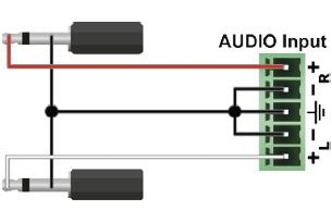
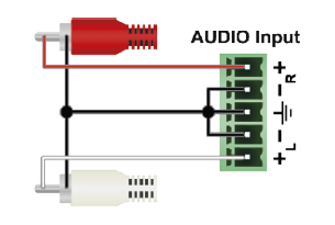
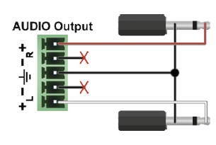
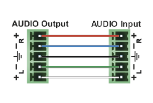
Inputs and outputs of audio devices are symmetric or asymmetric. The main advantage of the symmetric lines is the better protection against the noise, therefore they are widely used in the professional audio industry. Symmetric audio is most often referred to as balanced audio, as opposed to asymmetric, which is referred to as unbalanced audio. Ligthware products are usually built with 5-pole Phoenix connectors, so we would like to help users assemble their own audio cables. See the most common cases below.
▪Symmetric and asymmetric lines can be linked with passive accessories (e.g. special cables), but in this case half of the line level is lost.
▪There are numerous types of regularly used connector and cable types to connect audio devices. Please always make sure that a connector or cable fits your system before use.
▪Never join the phase-inverted (negative, cold or -) poles (either right or left) to the ground or to each other on the output side, as this can damage the unit.
▪Use a galvanic isolation in case of a ground loop.
The Pinout of the 5-pole Phoenix Connector

Compatible Plug Type: Phoenix® Combicon series (3.5mm pitch, 5-pole), type: MC 1.5/5-ST-3.5.
From Unbalanced Output to Balanced Input
|
2 x 6.3 (1/4") TS - Phoenix |
2 x RCA - Phoenix |
3.5 (1/8") TRS - Phoenix |
||
|
|

|
From Balanced Output to Unbalanced Input
|
Phoenix - 2 x 6.3 (1/4") TS |
Phoenix - 2 x RCA |
Phoenix - 3.5 (1/8") TRS |
||
|
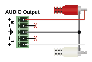
|

|
From Balanced Output to Balanced Input
|
Phoenix - 2 x 6.3 (1/4") TRS |
Phoenix - 2 x XLR |
2 x 6.3 TRS (1/4") - Phoenix |
||
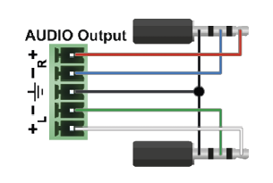
|
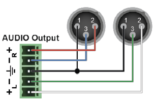
|

|
||
|
2 x XLR - Phoenix |
Phoenix - Phoenix |
|||
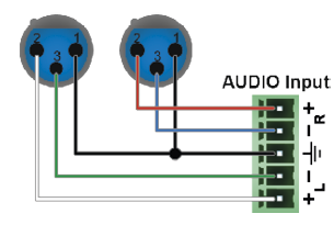
|
|
8.6. Further Document Information
Symbol Legend
The following symbols and markings are used in the document:
WARNING!Safety-related information that is highly recommended to read and keep in every case!
ATTENTION!Useful information for performing a successful procedure; it is recommended to read.
DIFFERENCE:Feature or function that is available with a specific firmware/hardware version or product variant.
INFO:A notice, which contains additional information. Procedure can be successful without reading it.
DEFINITION:The short description of a feature or a function.
TIPS AND TRICKS:Ideas that you may have not known yet, but can be useful.
Navigation Buttons
|
Buttons in the PDF version |
Buttons in the HTML version |
|||
|
|
Navigate to the Table of Contents. |
|
Open the main Table of Contents. |
|
|
|
Go back to the previous page. If you clicked on a link previously, you can go back to the source page by pressing the button. |
|
Navigate to the Online User Manuals webpage. |
|
|
|
Navigate to the Bookmark page. |
|
Navigate to the Bookmark page in this User Manual. |
|
|
|
Visit www.lightware.com. |
|
Download the PDF version of the User Manual. |
|


About Printing
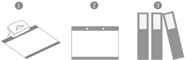
Lightware Visual Engineering supports green technologies and eco-friendly mentality. Thus, this document is made primarily for digital usage. If you need to print out a few pages for any reason, follow the recommended printing settings:
▪Page size: A4
▪Output size: Fit to page or Match page size
▪Orientation: Landscape
TIPS AND TRICKS: Thanks to the size of the original page, a border around the content (gray on the second picture below) makes it possible to organize the pages better. After punching holes in the printed pages, they can easily be placed into a ring folder.
8.7. Limited Warranty Statement
1. Lightware Visual Engineering PLC (Lightware) warrants to all trade and end user customers that any Lightware product purchased will be free from manufacturing defects in both material and workmanship for three (3) years from purchase unless stated otherwise below. The warranty period will begin on the latest possible date where proof of purchase/delivery can be provided by the customer. In the event that no proof can be provided (empty ‘Date of purchase’ field or a copy of invoice), the warranty period will begin from the point of delivery from Lightware.
1.1. 25G and MODEX product series will be subject to a seven (7) year warranty period under the same terms as outlined in this document.
1.2. If during the first three (3) months of purchase, the customer is unhappy with any aspect of a Lightware product, Lightware will accept a return for full credit.
1.3. Any product that fails in the first six (6) months of the warranty period will automatically be eligible for replacement and advanced replacement where available. Any replacements provided will be warranted for the remainder of the original unit’s warranty period.
1.4. Product failures from six (6) months to the end of the warranty period will either be repaired or replaced at the discretion of Lightware. If Lightware chooses to replace the product, then the replacement will be warranted for the remainder of the original unit’s warranty period.
2. The above-stated warranty and procedures will not apply to any product that has been:
2.1. Modified, repaired or altered by anyone other than a certified Lightware engineer unless expressly agreed beforehand.
2.2. Used in any application other than that for which it was intended.
2.3. Subjected to any mechanical or electrical abuse or accidental damage.
2.4. Any costs incurred for repair/replacement of goods that fall into the categories above (2.1., 2.2., 2.3.) will be borne by the customer at a pre-agreed figure.
3. All products to be returned to Lightware require a return material authorization number (RMA) prior to shipment, and this number must be clearly marked on the box. If an RMA number is not obtained or is not clearly marked on the box, Lightware will refuse the shipment.
3.1. The customer will be responsible for in-bound, and Lightware will be responsible for out-bound shipping costs.
3.2. Newly repaired or replaced products will be warranted to the end of the originally purchased product's warranty period.