
USER MANUAL

DVI-OPT-RX110
DVI-OPT-TX110
Small DVI Fiber Optical Extender
|
|
|
|
||
|
|
|
|
||
|
|
|
|
||




|
|
|
|
||


Class II apparatus construction.
The equipment should be operated only from the power source indicated on the product.
To disconnect the equipment safely from power, remove the power cord from the rear of the equipment, or from the power source. The MAINS plug is used as the disconnect device, the disconnect device shall remain readily operable.
There are no user-serviceable parts inside of the unit. Removal of the cover will expose dangerous voltages. To avoid personal injury, do not remove the cover. Do not operate the unit without the cover installed.
The appliance must be safely connected to multimedia systems. Follow instructions described in this manual..
Ventilation
For the correct ventilation and to avoid overheating, ensure enough free space around the appliance. Do not cover the appliance, leave the ventilation holes free and never block or bypass the ventilators (if there are any).
WARNING
To prevent injury, the apparatus is recommended to be securely attached to the floor/wall, or mounted in accordance with the installation instructions. The apparatus shall not be exposed to dripping or splashing, and no objects filled with liquids, such as vases, shall be placed on the apparatus. No naked flame sources, such as lit candles, should be placed on the apparatus.
Waste Electrical & Electronic Equipment (WEEE)

This marking shown on the product or its literature indicates that it should not be disposed with other household wastes at the end of its working life. To prevent possible harm to the environment or human health from uncontrolled waste disposal, please separate this from other types of wastes and recycle it responsibly to promote the sustainable reuse of material resources. Household users should contact either the retailer where they purchased this product or their local government office for details of where and how they can take this item for environmentally safe recycling. Business users should contact their supplier and check the terms and conditions of the purchase contract. This product should not be mixed with other commercial wastes for disposal.
Caution: Laser product



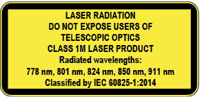
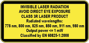
Common Safety Symbols
|
Symbol |
Description |

|
Direct current |

|
Alternating current |

|
Protective conductor terminal |

|
Equipotential Connector |

|
On (Power) |

|
Off (Power) |

|
Double insulation |

|
Caution, possibility of eletric shock |

|
Caution |

|
Laser radiation |

|
Warning, Rotating fan |

|
Caution: for indoor use only |
Document Revision History
|
Rev. |
Release date |
Changes |
Editor |
|
v1 |
2026-06-09 |
Initial release. |
Nikolett Keindl |
|
v2 |
2026-09-01 |
ToC correction. |
Laszlo Zsedenyi |
Contact Us
+36 1 255 3800
+36 1 255 3810
Lightware Visual Engineering PLC.
Gizella 51-57, Budapest H-1143, Hungary
©2026 Lightware Visual Engineering. All rights reserved.
All trademarks mentioned are the property of their respective owners.
Specifications are subject to change without notice.
Thank you for choosing Lightware’s DVI-OPT-110 series devices. In the first chapter we would like to introduce the device by highlighting the most important features in the sections listed below:
DVI-OPT-TX110 and DVI-OPT-RX110 pair is a DVI to fiber transmitter / receiver set for up to 2500 m distance transmission. Using Single Fiber Technology, the DVI-D signal is transmitted over only one multimode 50/125 fiber core. Sources and display devices are galvanically isolated against ground loops and hum effects, and no delay occurs in the signal, the video is transported without any frame latency.
About the Serial Number
Lightware devices contain a label indicating the unique serial number of the product. The structure is the following:

From 1st of October 2024, serial number format of Lightware devices is the following: the first two digits are of the year of manufacture, while the remaining digits make up the running sequence number.

|
Supplied accessories |
||||

|
|

|

|
|
|
Extender unit |
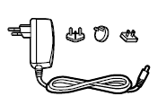
5V DC power adaptor with interchangeable plugs |
USB cable with 1.35/3.5 mm plug |
Safety and warranty info, Quick Start Guide |
|
|
DVI-OPT-RX110 |
|
|
|
|
|
DVI-OPT-TX110 |
|
|
|
|


|
2500 m Transmission Distance |
|
The extenders are capable of transmitting video signals over the fiber optical cable to up to 2500 meters. |
|

|
No Signal Latency |
|
The extenders transmit video signal to great distances with zero frame latency. |
1.4.1. Typical Standalone Application
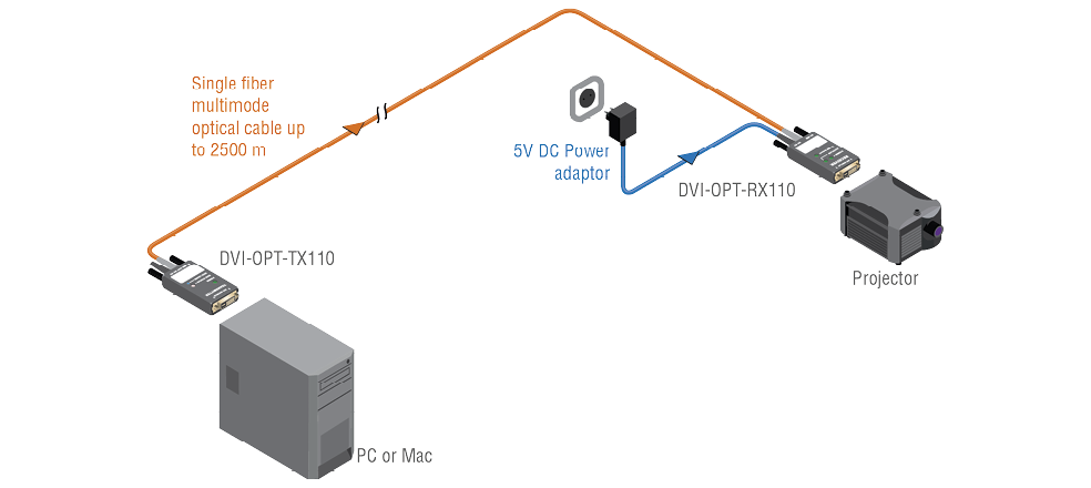
1.4.2. Integrated System Application
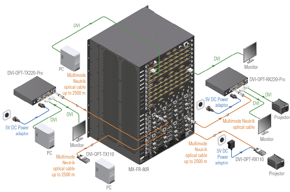
2
The following sections are about the physical structure of the device, their connectors, LEDs and button control:

|
|
DVI Input |
Connect to a DVI source for transmitting a DVI signal or connect to a sink device for learning the EDID; see the Learning an EDID section. |
|
|
Power LED |
The LED lights green if the power supply is sufficient (DVI or external adaptor supply). |
|
|
EDID LED |
Three-colored LED displays the EDID status. See the Status LEDs section for more information. |
|
|
Learn Button |
Press the button for 2 seconds to activate Learn mode. Press for 10 seconds to restore the factory default EDID. |
|
|
Power Connector |
Barrel plug receptacle for external power adaptor. |
|
|
Fiber Connector |
SC type receptacle for multimode fiber output. |


|
|
DVI Output |
Connect to a DVI display. |
|
|
Power LED |
Lights green is the unit is powered on. |
|
|
Hotplug LED |
Indicates that the display device is connected correctly. |
|
|
Laser LED |
Green light indicates that the laser is properly detected on the optical input. |
|
|
Power Connector |
Barrel plug receptacle for external power adaptor. |
|
|
Fiber Connector |
SC type receptacle for multimode fiber input. |
2.2.1. Using the LEARN Button (Transmitter)
▪When the button is pressed, the EDID state LED turns off to indicate the button press.
▪If the button is released sooner than two seconds, the press will be ignored.
▪If the button is pressed for more than two seconds, the EDID learn mode gets activated for a period of 10 seconds.
▪If the button is pressed for more than 10 seconds and the unit is not connected to a display device, the factory default EDID will be restored.
2.2.2. Learning an EDID (Transmitter)
Step 1.Plug in the power adaptor to an electrical outlet, or plug in the enclosed USB power cable to a USB connector, and then connect the DC cable to the transmitter.
Step 2.The power and the EDID state LEDs light up.
Step 3.Press and hold down the LEARN button for two seconds. The EDID state LED goes dark, and then lights up orange to indicate that Learn mode is activated.
Step 4.Connect the transmitter to a display device; the learn mode is active for 10 seconds.
Step 5.The transmitter reads the EDID from the display device. Do not disconnect the device while it lights orange (approximately 10 seconds).
Step 6.Check if the learning succeeded:
=If the learning process was successful, the EDID state LED blinks green slowly for eight seconds. The stored EDID is changed.
=If the learning process failed, the EDID state LED blinks red slowly for eight seconds. The previously stored EDID remains in the memory.
=The EDID state LED changes to continuous green or red depending on the validity of the stored EDID.
Step 7.Disconnect the transmitter (if still connected) and the power supply. The stored EDID remains in the memory until it is overwritten. The unit is ready to be used for DVI signal extension.
2.2.3. Restoring the Factory Default EDID (Transmitter)
Step 1.Power up the transmitter by
=a) using one of the external power supplies
=b) connecting it to a DVI source.
Step 2.Press and keep pressing the LEARN button. The EDID state LED goes dark for two seconds, and then turns orange to indicate that learn mode is activated. (Do not connect the unit to a display device.)
Step 3.Keep the button pressed until the LED starts to blink orange (after approximately 10 seconds). Five blinks indicate the EDID restoration process.
Step 4.After the restoration process is finished, the LED blinks green slowly for eight seconds. The stored EDID is changed back to factory default (1920x1200@59.55Hz).
Step 5.The unit is ready to be used for DVI signal extension.
2.3.1. EDID Status LED (Transmitter)
|
LED light |
Meaning |
|

|
GREEN continuously |
EDID is valid |

|
RED continuously |
EDID is invalid |

|
ORANGE continuously |
EDID Learn mode is active |

|
GREEN blinking |
EDID learning is success |

|
RED blinking |
EDID learning failed |

|
ORANGE blinking fast |
Reloading factory EDID |

|
ORANGE blinking slowly |
Laser module failure |
INFO:After powering on, the DVI-OPT-TX110 unit shows its three-digit firmware version with red, green and orange blinks (e.g. FW v1.1.6 is: 1x red, 1x green, 6x orange).
3
This chapter is about the installation of the device and connecting to other appliances:

Locking DC connector
The extenders are built with a locking 5V DC connector. Do not forget to turn the plug clockwise before disconnecting the power adaptor.
WARNING!Always use the supplied 5V power adaptor. Warranty void if damage occurs due to use of a different power source.
3.1.2. SC Fiber Optical Connector

HDMI-3D-OPT-DD series transmitter and receiver provide multimode SC fiber optical input and output connectors.
Maximum fiber cable distances can be found in the Maximum Fiber Cable Extensions section.
WARNING!Please do not look directly into the SC fiber optical connector if the cable is connected to the transmitter only and the laser is active.

29 pole DVI-I connectors only have digital pins internally connected. This way, users can plug in any DVI connector, but keep in mind that analog signals (such as VGA or RGBHV) are NOT available.

A 5V DC power adaptor supplied with the extender that is suitable to power the unit.
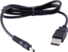
A special USB-A-DC cable with a 1.35/3.5 mm plug on the other end that is supplied with the extender and can be used to supply the unit with power.
3.2.3. DVI Connector (via +5V pin)
In case the unit is connected to a device (e.g. a matrix) that contains DVI outputs that are able to supply 500 mA current on DDC +5V output (pin 14 on output connectors) which is sufficient to supply power to hybrid fiber optical DVI cables. Standard DVI outputs usually supply only 55 mA current on +5V output, thus are unable to directly power a fiber optical cable.


|
Connect a multimode SC fiber cable to the SC MM IN connector on the DVI-OPT-RX110 unit. |
|

|
Connect the receiver to the DVI sink (e.g. monitor). |
|

|
Power on the DVI sink (monitor). |
|

|
Connect the other end of the multimode SC fiber cable to the SC MM OUT connector on the DVI-OPT-TX110 unit. |
|

|
Connect the transmitter to a DVI source (e.g. computer). |
|

|
Power on the DVI source (computer). It reads the EDID from the transmitter and outputs the video signal according to the set resolution. |
|
|
Check the LEDs on the transmitter: |
If both the Power LED and the EDID status LEDs are green, the transmitter is ready to use. |
|
|
If the Power LED does not light up, the DVI source does not send enough power through the DVI connector, so the external power adaptor or the special USB cable needs to be connected to the transmitter. |
||
|
If the EDID state LED lights red, an EDID needs to be learned. |
||
4
Usually, if the system seems not to transport the signal as expected, the best strategy for troubleshooting is to check signal integrity through the whole signal chain starting from source side and moving forward to receiver end:
At first, check front panel LEDs and take the necessary steps according to their states. For more information about front and rear panel LEDs of the devices, refer to Status LEDs sections.
Legend

|
Link to the section of connections/cabling. |
|
Symptom |
Root cause |
Action |
Refer to |
|
|---|---|---|---|---|
|
The transmitter will not power on |
The DVI source might not supply enough power to the transmitter. |
Use one of the external power supply methods in this case. |

|
|
|
The image is noisy |
The fiber cables may be dirty. |
Make sure the fiber cables are clean. |

|
|
4.2. How to Speed Up the Troubleshooting Process

Lightware’s technical support team is always working hard to provide the fastest support possible. Our team’s response time is one of the best in the industry, and in the toughest of cases we can directly consult with the hardware or software engineer who designed the product to get the information from the most reliable source.
However, the troubleshooting process can be even faster… with your help.
There are certain pieces of information that push us in the right direction to find the root cause of the problem. If we receive most of this information in the first e-mail, or it is gathered at the time when you call us, then there is a pretty high chance that we will be able to respond with the final solution right away. This information is the following:
▪Schematic (a pdf version is preferred, but a hand drawing is sufficient).
▪Serial number(s) of the device(s) (it is either printed somewhere on the box or you can query it in the Device Controller software or on the built-in website).
▪Firmware versions of the devices (please note that there may be multiple CPUs or controllers in the device and we need to know all of their firmware versions, a screenshot is the best option).
▪Cable lengths and types (in our experience, it’s usually the cable).
▪Patch panels, gender changers or anything else in the signal path that can affect the transmission.
▪Signal type (resolution, refresh rate, color space, deep color).
▪Emulated EDID(s) (please save them as a file and send it to us).
▪Actions to take in order to re-create the problem (if we cannot reproduce the problem, it is hard for us to find the cause).
▪Photo or video about the problem (‘image noise’ can mean many different things, it’s better if we see it too).
▪Error logs from the Device Controller software.
▪In the case of Event Manager issue, the event file and/or backup file from the Device Controller software.
▪The more of the information above you can give us, the better. Please send this information to the Lightware Support Team (support@lightware.com) to speed up the troubleshooting process.
5
Tables, drawings, guides, and technical details as follows:
INFO:Specifications are subject to change without notice.
General
|
Compliance |
CE, UKCA |
|
EMC (emission) |
EN 55032:2015+A1:2020 |
|
EMC (immunity) |
EN 55035:2017+A11:2020 |
|
RoHS |
EN 63000:2018 |
|
Electrical safety |
EN 62368-1:2020 |
|
Laser safety |
EN 60825-1:2014+A11:2021 |
|
Warranty |
3 years |
|
Operating temperature |
0° to +40˚C (+32° to +104˚F) |
|
Operating humidity |
10% to 80%, non-condensing |
|
Cooling |
Passive |
Power
|
Power supply option |
power adaptor / USB / DVI port |
|
Power consumption (TX) |
1.4 W |
|
Heat dissipation (TX) |
5 BTU/h |
|
Power consumption (RX) |
0.8 W |
|
Heat disspation (RX) |
3 BTU/h |
Power adaptor
|
Supported power source |
100-240 V AC; 50/60 Hz |
|
Supplied power |
5V DC, 1A |
|
AC power plug |
Interchangeable (EU, UK, JP/US, AUS/NZ) |
|
DC power plug |
Locking DC connector (1.35 / 3.5 mm pin) |
Enclosure
|
Enclosure material |
solid steel |
|
Dimensions in mm |
39 W x 87.5 D x 15.4 H |
|
Dimensions in inch |
1.6 W x 3.5 D x 0.6 H |
|
Weight (TX) |
200 g (0.44 lb) |
|
Weight (RX) |
205 g (0.45 lb) |
Video Input (DVI-OPT-TX110)
|
Connector type |
29-pole DVI-I (digital only) |
|
AV standard |
DVI 1.0 |
|
Video delay |
0 frame |
|
Supported resolutions at 8 bits/color |
up to 1920x1200 or 2048x1080 pixel |
|
Recklocking |
Pixel Accurate Reclocking |
|
EDID emulation |
Yes, with LEARN button |
|
EDID memory |
1 pc.user programmable EDID |
|
Factory EDID |
1920x1200@59.55Hz |
Video Output (DVI-OPT-RX110)
|
Connector type |
29-pole DVI-I (digital only) |
|
AV standard |
DVI 1.0 |
|
Video delay |
0 frame |
|
Supported resolutions at 8 bits/color |
up to 1920x1200 or 2048x1080 pixel |
|
Recklocking |
Pixel Accurate Reclocking |
|
EDID emulation |
Yes, with LEARN button |
|
EDID memory |
1 pc.user programmable EDID |
|
Factory EDID |
1920x1200@59.55Hz |
Fiber Optical Ports
|
Connector type |
SC simplex |
|
Applicable cable |
multimode, 50/125 |
|
Laser class specification |
Class 3R |
|
Laser wavelengths |
4 channel: 778; 800; 825; 850 nm |
|
DVI-OPT-TX110 output OMA* (max) |
-6.25 dBm |
|
DVI-OPT-RX110 OMA* sensitivity (max) |
-14.25 dBm |
|
Maximum transmission distance |
2500 m (using OM4 type optical cable) |
*Optical Modulation Amplitude
5.2. Maximum Fiber Cable Extensions
|
OM1 |
OM2 |
OM3 |
OM4 |
|
|
1060p@60Hz |
250 m |
600 m |
1200 m |
2500 m |

5.4. Further Document Information
Symbol Legend
The following symbols and markings are used in the document:
WARNING!Safety-related information that is highly recommended to read and keep in every case!
ATTENTION!Useful information for performing a successful procedure; it is recommended to read.
DIFFERENCE:Feature or function that is available with a specific firmware/hardware version or product variant.
INFO:A notice, which contains additional information. Procedure can be successful without reading it.
DEFINITION:The short description of a feature or a function.
TIPS AND TRICKS:Ideas that you may have not known yet, but can be useful.
Navigation Buttons
|
Buttons in the PDF version |
Buttons in the HTML version |
|||
|
|
Navigate to the Table of Contents. |
|
Open the main Table of Contents. |
|
|
|
Go back to the previous page. If you clicked on a link previously, you can go back to the source page by pressing the button. |
|
Navigate to the Online User Manuals webpage. |
|
|
|
Navigate to the Bookmark page. |
|
Navigate to the Bookmark page in this User Manual. |
|
|
|
Visit www.lightware.com. |
|
Download the PDF version of the User Manual. |
|


About Printing

Lightware Visual Engineering supports green technologies and eco-friendly mentality. Thus, this document is made primarily for digital usage. If you need to print out a few pages for any reason, follow the recommended printing settings:
▪Page size: A4
▪Output size: Fit to page or Match page size
▪Orientation: Landscape
TIPS AND TRICKS: Thanks to the size of the original page, a border around the content (gray on the second picture below) makes it possible to organize the pages better. After punching holes in the printed pages, they can easily be placed into a ring folder.
5.5. Limited Warranty Statement
1. Lightware Visual Engineering PLC (Lightware) warrants to all trade and end user customers that any Lightware product purchased will be free from manufacturing defects in both material and workmanship for three (3) years from purchase unless stated otherwise below. The warranty period will begin on the latest possible date where proof of purchase/delivery can be provided by the customer. In the event that no proof can be provided (empty ‘Date of purchase’ field or a copy of invoice), the warranty period will begin from the point of delivery from Lightware.
1.1. 25G and MODEX product series will be subject to a seven (7) year warranty period under the same terms as outlined in this document.
1.2. If during the first three (3) months of purchase, the customer is unhappy with any aspect of a Lightware product, Lightware will accept a return for full credit.
1.3. Any product that fails in the first six (6) months of the warranty period will automatically be eligible for replacement and advanced replacement where available. Any replacements provided will be warranted for the remainder of the original unit’s warranty period.
1.4. Product failures from six (6) months to the end of the warranty period will either be repaired or replaced at the discretion of Lightware. If Lightware chooses to replace the product, then the replacement will be warranted for the remainder of the original unit’s warranty period.
2. The above-stated warranty and procedures will not apply to any product that has been:
2.1. Modified, repaired or altered by anyone other than a certified Lightware engineer unless expressly agreed beforehand.
2.2. Used in any application other than that for which it was intended.
2.3. Subjected to any mechanical or electrical abuse or accidental damage.
2.4. Any costs incurred for repair/replacement of goods that fall into the categories above (2.1., 2.2., 2.3.) will be borne by the customer at a pre-agreed figure.
3. All products to be returned to Lightware require a return material authorization number (RMA) prior to shipment, and this number must be clearly marked on the box. If an RMA number is not obtained or is not clearly marked on the box, Lightware will refuse the shipment.
3.1. The customer will be responsible for in-bound, and Lightware will be responsible for out-bound shipping costs.
3.2. Newly repaired or replaced products will be warranted to the end of the originally purchased product's warranty period.